Note: Descriptions are shown in the official language in which they were submitted.
CA 02788477 2012-07-27
WO 2011/094151 PCT/US2011/022222
TRANSMISSION HAVING A FLUID COOLING SHROUD
CROSS-REFERENCE TO RELATED APPLICATION
[0001] Not Applicable.
STATEMENT CONCERNING FEDERALLY SPONSORED
RESEARCH OR DEVELOPMENT
[0002] Not Applicable.
BACKGROUND OF THE INVENTION
[0003] This invention relates to transmissions having external fluid coolers.
[0004] Transmissions such as industrial gear drives are capable of
transmitting a
large amount of mechanical power. Unfortunately, some of the transmitted power
is
converted to heat that may increase the transmission temperature to an
unacceptably
high level. Such temperatures may cause lubricating fluid within the
transmission
housing to deteriorate rapidly and ultimately lead to component wear or
failure.
[0005] As such, many transmissions include heat dissipation components to
prevent
overheating. For example, some transmissions simply include a fan to provide
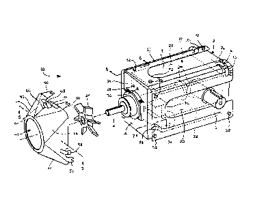
convective cooling by blowing air over the external surfaces of the
transmission
housing. However, these heat dissipation systems, despite being structurally
simple
and relatively inexpensive, are typically ineffective for significantly
decreasing the
transmission temperature unless they are much larger than the transmission
itself.
[0006] As another example, some transmissions include external radiators or
heat
pipes having internal chambers to accommodate the lubricating fluid and permit
cooling
outside of the transmission housing. Like the fan systems described above,
relatively
large radiators, e.g., those having a relatively large surface, are most
effective for
1
CA 02788477 2012-07-27
WO 2011/094151 PCT/US2011/022222
cooling a transmission. As such, the most effective heat dissipation
components can
significantly increase the space required for a transmission.
[0007] Considering the drawbacks of previous designs, a transmission having
improved heat dissipation components is needed.
SUMMARY OF THE INVENTION
[0008] In one aspect, the present invention provides a transmission including
a
housing having housing walls defining an internal chamber and a rotatable
input shaft
extending through one of the housing walls into the internal chamber. Power
transmission components are disposed in the internal chamber and rotatably
driven by
the input shaft. An output shaft extends through one of the housing walls from
the
internal chamber and is rotatably driven by the power transmission components.
A
lubricating fluid is disposed in the internal chamber and lubricates the power
transmission components. A cooling shroud surrounds the housing and defines a
gap
between at least one of the housing walls. The cooling shroud includes a
cooling
passageway in fluid communication with the internal chamber. The lubricating
fluid
flows out of the internal chamber into the cooling passageway, through the
cooling
passageway, and back into the internal chamber. The transmission further
includes a
fan exhausting air through the gap cooling the at least one of the housing
walls and the
lubricating fluid flowing through the cooling passageway.
[0009] In some embodiments, the cooling shroud includes fan shroud surrounding
the fan and a housing shroud surrounding the housing.
[0010] The foregoing and advantages of the invention will appear in the
detailed
description which follows. In the description, reference is made to the
accompanying
drawings which illustrate a preferred embodiment of the invention.
2
CA 02788477 2012-07-27
WO 2011/094151 PCT/US2011/022222
BRIEF DESCRIPTION OF THE DRAWINGS
[0011] The invention will hereafter be described with reference to the
accompanying
drawings, wherein like reference numerals denote like elements, and:
[0012] FIG. 1 is a perspective view of a transmission including a cooling
shroud
according to the present invention;
[0013] FIG. 2 is an exploded perspective view showing a fan of the
transmission of
FIG. 1;
[0014] FIG. 3 is a front view of the transmission of FIG. 1 with the fan and a
fan
shroud removed;
[0015] FIG. 4 is a "flattened" schematic view of a housing shroud showing a
fluid flow
path there through;
[0016] FIG. 5 is a top sectional view of the fan shroud along line 5-5 of FIG.
2;
[0017] FIG. 6 is a detail section view of the transmission along line 6-6 of
FIG. 2;
[0018] FIG. 7 is a detail section view of the transmission along line 7-7 of
FIG. 2;
[0019] FIG. 8 is a perspective view of a second embodiment of a transmission
including a fan shroud according to the present invention;
[0020] FIG. 9 is a top sectional view of the fan shroud along line 9-9 of FIG.
8;
[0021] FIG. 10 is a front view of a third embodiment of a transmission
according to
the present invention with the fan and the fan shroud removed;
[0022] FIG. 11 is a detail section view of the transmission of FIG. 10.
DETAILED DESCRIPTION OF THE INVENTION
[0023] The particulars shown herein are by way of example and only for
purposes of
illustrative discussion of the embodiments of the invention. The particulars
shown
herein are presented to provide what is believed to be the most useful and
readily
understood description of the principles and conceptual aspects of the
invention. In this
3
CA 02788477 2012-07-27
WO 2011/094151 PCT/US2011/022222
regard, no attempt is made to show structural details of the invention in more
detail than
is necessary for the fundamental understanding of the invention. The
description taken
with the drawings should make apparent to those skilled in the art how the
several
forms of the present invention may be embodied in practice.
[0024] Referring to FIGS. 1-2, a transmission 10 according to the present
invention
includes a housing 12 that rotatably supports an input shaft 14 and an output
shaft 16
driven by the input shaft 14. The housing 12 includes a housing walls 18
having a front
surface 20 and right side surface 22 from which the input shaft 14 and the
output shaft
16 extend, respectively. As such, the transmission 10 is a right angle shaft
transmission. The output shaft 16 may also extend from a left side surface 24
of the
housing 12. Furthermore, the output shaft 16 may extend from a surface
opposite the
front surface 20, i.e., a rear surface 26 of the housing 12, to provide a
parallel shaft
transmission without departing from the scope of the invention. The housing
walls 18
also include an upper surface 28 having a removable inspection cover (not
shown).
The upper surface 28 is adjacent the front surface 20, the right side surface
22, the left
side surface 24, and the rear surface 26. As used herein, the term "adjacent"
means
that two surfaces share a common edge. In contrast and as used herein, the
term
"opposite" means that two surfaces do not share a common edge.
[0025] The input shaft 14 supports a fan 27 that draws air towards the
transmission
housing 12 as in the input shaft 14 rotates. The fan 27 can also be driven by
the output
shaft 16 or can be completely independent of the shafts 14 and 16 without
departing
from the scope of the invention. Regardless of the specific structure, the fan
27
exhausts air along the housing walls 18 to cool the housing 12 and thereby
prevent the
transmission 10 from overheating. Other components that further dissipate heat
from
the transmission 10 are described in further detail below.
4
CA 02788477 2012-07-27
WO 2011/094151 PCT/US2011/022222
[0026] As shown most clearly in FIG. 2, the housing walls 18 define an
internal
chamber 30 in which power transmission components 29 are disposed. The power
transmission components 29 may be, e.g., bevel gears and helical gears.
However,
other types of gears, e.g., spur gears, worm gears, planetary gears, helical
gears,
combinations thereof, or even other types of power transmission components may
be
used without departing from the scope of the invention. In any case, the power
transmission components provide the driving relationship between the input
shaft 14
and the output shaft 16.
[0027] The internal chamber 30 of the housing 12 also accommodates a
lubricating
fluid 32 that reduces transmission wear by absorbing heat generated by the
transmission components. As such, the internal chamber 30 also preferably
accommodates a pump 34 that delivers lubricating fluid 32 to a housing output
port 36
for subsequent cooling. However, the lubricating fluid 32 may be directed to
the output
port 36 by other means, e.g., gravity, without departing from the scope of the
invention.
In any case, after cooling the lubricating fluid 32 returns to the internal
chamber 30
through a housing input port 38.
[0028] Referring now to FIGS. 1-7, the transmission housing 12 supports a
radiator
jacket or cooling shroud 40 having a cooling circuit or passageway through
which the
lubricating fluid 32 flows to cool. The shape of the cooling shroud 40
advantageously
closely matches the external shape of the transmission housing 12, and
therefore the
cooling shroud 40 does not significantly increase the space required for the
transmission 10. That is, the cooling shroud 40 includes a fan shroud 42 that
surrounds
the input shaft 14 and the fan 27 and a housing shroud 60 that surrounds the
housing
12. The fan shroud 42 and the housing shroud 60 are described in further
detail in the
following paragraphs, but it should be noted that as used herein, the term
"surround"
CA 02788477 2012-07-27
WO 2011/094151 PCT/US2011/022222
and variations thereof means a shroud is disposed proximate at least two
opposite
surfaces of another object.
[0029] The fan shroud 42 has a general open-bowl shape through which air is
drawn
by the fan 27 and directed towards the housing walls 18. That is, air is drawn
through
an air input 43 and directed towards an air output 45 proximate the front
surface 20 of
the housing 12. The air input 43 and the air output 45 are separated by
diagonally
extending walls that provide the open-bowl shape of the fan shroud 42. The
open-bowl
shape of the fan shroud 42 is also formed by a right half 47 and a left half
49 that
together surround the input shaft 14 and the fan 27. The halves 47 and 49 may
connect
to each other by fasteners, or as shown in the figures, by diagonally
extending weld
lines 66.
[0030] As shown most clearly in FIG. 5, the walls of the halves 47 and 49 are
defined
by an inner layer 44 and an outer layer 46 that are preferably shaped sections
of sheet
metal, although other materials may be used without departing from the scope
of the
invention. In any case, the inner layer 44 and the outer layer 46 are spaced
apart to
define the cooling passageway there between. Of course, the edges of the inner
layer
44 and an outer layer 46 are sealed, e.g., by weld lines 48, to prevent
lubricating fluid
32 leaks.
[0031] The right and left halves 47 and 49 of the fan shroud 42 each define
separate
sections of the cooling passageway through which the lubricating fluid 32
passes. For
example, lubricating fluid 32 enters the right half 47 through a shroud input
port 54
disposed near the upper surface 28 of the transmission housing 12 and
connected to
the housing output port 36. The shroud input port 54 delivers lubricating
fluid 32 to an
input passage 56 of the cooling passageway defined between the inner and outer
layers
44 and 46 of the right half 47. The input passage 56 delivers lubricating
fluid 32 to a fan
6
CA 02788477 2012-07-27
WO 2011/094151 PCT/US2011/022222
shroud output port 58 disposed near the bottom corner of the front surface 20
and the
right side surface 22 of the transmission housing 12. The fan shroud output
port 58
delivers lubricating fluid 32 to the housing shroud 60.
[0032] Similarly, lubricating fluid 32 from the housing shroud 60 enters the
left half 49
through a fan shroud input port 62 disposed near the bottom comer of the front
surface
20 and the left side surface 24 of the transmission housing 12. The fan shroud
input
port 62 delivers lubricating fluid 32 to an output passage 64 of the cooling
passageway
defined between the inner and outer layers 44 and 46 of the left half 49. The
output
passage 64 delivers lubricating fluid 32 to a shroud output port 68 disposed
near the
upper surface 28 of the transmission housing 12 and connected to the housing
input
port 38.
[0033] The right and left halves 47 and 49 of the fan shroud 42 may connect to
the
transmission housing 12, the housing shroud 60, or both in various manners.
For
example, the edges of the fan shroud 42 may be welded to the housing shroud
60.
However and as shown in the figures, the outer sheet metal layer 46 preferably
forms
several mounting feet 50 that accommodate fasteners 52, e.g., bolts and
spacers, to
connect the fan shroud 42 to the transmission housing 12.
[0034] Referring now to FIGS. 2-7 and as briefly described above, the housing
shroud 60 receives lubricating fluid 32 from the fan shroud 42 to further
dissipate heat
from the transmission 10. The housing shroud 60 has a general saddle shape
(i.e., the
housing shroud 60 is positioned proximate the upper surface 28 and side
surfaces 22
and 24 of the housing 12) that extends between the front surface 20 and the
rear
surface 26 of the transmission housing 12. In addition, the cooling passageway
follows
a serpentine path over the general saddle shape of the housing shroud 60, and
as such
the housing shroud 60 has a relatively large surface area over which the
lubricating fluid
7
CA 02788477 2012-07-27
WO 2011/094151 PCT/US2011/022222
32 dissipates heat. Furthermore, the housing shroud 60 is spaced apart from
the
surfaces 22, 24, and 28 of the transmission housing 12 to define a gap 75
there
between. Air exhausted by the fan 27 passes through the gap 75 and
convectively
cools the housing walls 18 and the lubricating oil 32 within the housing
shroud 60.
[0035] Like the fan shroud 42, the housing shroud 60 is defined by an inner
layer 70
and an outer layer 72 (e.g., separate sheet metal layers connected by weld
lines 74)
that form part of the cooling passageway there between. The inner and outer
layers 70
and 72 also form three panels 76, 92, and 106 that provide the serpentine
shape of the
cooling passageway. As shown in the figures, the panels 76, 92, and 106 are
preferably integrally connected to each other (i.e., formed by the same inner
and outer
layers 70 and 72). However, the panels 76, 92, and 106 may be formed from
separate
layers without departing from the scope of the invention.
[0036] Each of the shroud panels 76, 92, and 106 defines part of the
serpentine
shape of the cooling passageway that directs lubricating fluid 32 back and
forth between
the front surface 20 and the rear surface 26 of the housing 12. For example,
the first or
right side surface shroud panel 76 disposed proximate the right side surface
22 of the
housing 12 defines an S-shaped section of the serpentine flow path. This S-
shaped
section is formed by the following components and features of the first panel
76.
[0037] A first or right side surface shroud input port 78 is disposed near the
bottom
comer of the front surface 20 and the right side surface 22 of the
transmission housing
12. The input port 78 receives lubricating fluid 32 from the fan shroud 42 and
delivers
lubricating fluid 32 to a first leg 80 of the cooling passageway. The first
leg 80 connects
to a second leg 82 of the cooling passageway near the rear surface 26 of the
transmission housing 12. An internal wall, e.g., a weld line 84 connecting the
housing
8
CA 02788477 2012-07-27
WO 2011/094151 PCT/1JS2011/022222
shroud inner and outer layers 70 and 72 separates a majority of the first leg
80 and the
second leg 82.
[0038] The second leg 82 connects to a third leg 86 of the cooling passageway
near
the front surface 20 of the transmission housing 12. A first shroud opening 88
separates a majority of the second leg 82 and the third leg 86. The output
shaft 16
extends through the first shroud opening 88 and, of course, air may escape
from the air
gap 75 through the first shroud opening 88. The third leg 86 delivers
lubricating fluid 32
to a first or right side surface shroud output port 90 disposed near the top
comer of the
rear surface 26 and the right side surface 22 of the transmission housing 12.
[0039] The first panel 76 connects to the second or upper surface shroud panel
92
proximate the upper surface 28 of the housing 12. The second panel 92 defines
a U-
shaped section of the serpentine flow path. This U-shaped section is formed by
the
following components and features of the second panel 92.
[0040] A second or upper surface shroud input port 94 is disposed near the top
comer of the rear surface 26 and the right side surface 22 of the transmission
housing
12. The second or upper surface shroud input port 94 connects to the first
output port
90 and receives lubricating fluid 32 therefrom. The second port 94 also
delivers
lubricating fluid 32 to a fourth leg 96 of the cooling passageway. The fourth
leg 96 is
preferably separated from the third leg 86 of the first panel 76 by an
internal wall, e.g., a
weld line 98 connecting the housing shroud inner and outer layers 70 and 72.
[0041] The fourth leg 96 connects to a fifth leg 100 near the front surface 20
of the
transmission housing 12. A second shroud opening 102 separates a majority of
the
fourth leg 96 and the fifth leg 100. The removable inspection cover may be
accessed
through the second shroud opening 102 and, of course, air may escape from the
air gap
75 through the second shroud opening 102. The fifth leg 100 delivers
lubricating fluid
9
CA 02788477 2012-07-27
WO 2011/094151 PCT/US2011/022222
32 to a second or upper surface shroud output port 104 disposed near the top
comer of
the rear surface 26 and the left side surface 24 of the transmission housing
12.
[0042] The second panel 92 connects to a third or left side surface shroud
panel 106
proximate the left side surface 24 of the housing 12. The third panel 106
defines an
inverted S-shaped section of the serpentine flow path. This inverted S-shaped
section
is formed by the following components and features of the first panel 106.
[0043] A third or left side surface shroud input port 108 is disposed near the
top
comer of the rear surface 26 and the left side surface 24 of the transmission
housing
12. The third input port 108 connects to the second shroud output port 104 and
receives lubricating fluid 32 therefrom. The third input port 108 delivers
lubricating fluid
32 to a sixth leg 110 of the cooling passageway. The sixth leg 110 is
preferably
separated from the fifth leg 100 of the second panel 92 by an internal wall,
e.g., a weld
line 111 connecting the housing shroud inner and outer layers 70 and 72.
[0044] The sixth leg 110 connects to a seventh leg 112 of the cooling
passageway
near the front surface 20 of the transmission housing 12. A third shroud
opening 114
separates a majority of the sixth leg 110 and the seventh leg 112. The output
shaft 16
may extend through the third shroud opening 114 and, of course, air may escape
from
the air gap 75 through the third shroud opening 114.
[0045] The seventh leg 112 connects to an eighth leg 116 of the cooling
passageway
near the rear surface 26 of the transmission housing 12. An internal wall,
e.g., a weld
line 118 connecting the housing shroud inner and outer layers 70 and 72,
separates a
majority of the seventh leg 112 and the eighth leg 116. The eighth leg 116
delivers
lubricating fluid 32 to a third or left side surface shroud output port 120
disposed near
the bottom comer of the front surface 20 and the left side surface 24 of the
transmission
housing 12.
CA 02788477 2012-07-27
WO 2011/094151 PCT/US2011/022222
[0046] As briefly described above, the third output port 120 connects to the
fan
shroud input port 62 to deliver lubricating fluid 32 to the output passage 64
of the fan
shroud left half 49. The output passage 64 then directs the lubricating fluid
32 to the
shroud output port 68 connected to the housing input port 38 to return the
fluid 32 to the
internal chamber 30 of the transmission housing 12.
[0047] Like the fan shroud 42, the housing shroud 60 may connect to the
transmission housing 12, the fan shroud 42, or both in various manners. For
example,
the housing shroud 60 may be welded to the fan shroud 42. However and as shown
in
the figures, the housing shroud 60 preferably connects to the housing 12 via
fasteners
52, some of which also connect the fan shroud 42 to the housing 12. In this
case,
spacers of the fasteners 52 separate the panels 76, 92, and 106 from the
housing walls
18 to form the gap 75 there between.
[0048] In operation, the lubricating fluid 32 flows out of the internal
chamber 30 of the
transmission housing 12 through the housing output port 36 and into the input
passage
56 of the fan shroud right half 47. The lubricating fluid 32 then flows
through the
serpentine section of the cooling passageway formed by the housing shroud
panels 76,
92, and 106. The housing shroud 60 delivers the lubricating fluid 32 to the
output
passage 64 of the fan shroud left half 49. The lubricating fluid 32 then flows
back into
the internal chamber 30 of the housing 12 through the housing input port 38.
Of course,
the fan 27 simultaneously exhausts air into the air gap 75 to cool the housing
walls 18
and the lubricating fluid 32 flowing through the cooling passageway provided
by the
cooling shroud 40.
[0049] The structure of the cooling shroud 40 may vary from the above
description
without departing from the scope of the invention. For example, the housing
shroud 60
may provide a flow path for the lubricating fluid 32 having a different shape
than the
11
CA 02788477 2012-07-27
WO 2011/094151 PCT/US2011/022222
serpentine flow path described above. Nevertheless, such a housing shroud 60
preferably has a relatively large surface area over which the lubricating
fluid 32
dissipates heat.
[0050] As another example, the weld lines 98 and 118 and the shroud openings
88,
102, and 114 may be shorter than those as shown and described. However, these
features preferably extend over the majority of the length between the front
and rear
surface 20 and 26 to provide a relatively large surface area for relatively
high heat
transfer with the air gap 75.
[0051] As yet another example, right and left halves 47 and 49 of the fan
shroud 42
may be formed from common inner and outer layers 44 and 46. In this case, the
input
passage 56 and the output passage 64 of the fan shroud 42 may be separated by
an
internal wall, e.g., a weld line 66 connecting the inner and outer layers 44
and 46.
[0052] As yet another example and referring now to FIGS. 8 and 9, a second
embodiment of a transmission 210 according to the present invention includes a
fan
shroud 242 having a general U-shape as viewed from above. Like the fan shroud
42
described above, the fan shroud 242 includes an inner layer 244 and an outer
layer 246
(e.g., shaped sections of sheet metal) that define fluid cooling passageways
256 and
264 there between. However, the fan input 243 includes a plurality of small
input slits
247 through which air enters the fan shroud 242.
[0053] As yet another example and referring now to FIGS. 10 and 11, a third
embodiment of a transmission 310 according to the present invention includes a
housing shroud 360 having additional panels to further dissipate heat from the
transmission 310. That is, the housing shroud 360 includes panels 376, 392,
and 406
as described above as well as inner panels 376', 392', and 406' disposed in
the air gap
375 adjacent the transmission housing walls 318. The inner panels 376', 392',
and 406'
12
CA 02788477 2012-07-27
WO 2011/094151 PCT/US2011/022222
may provide the same general saddle shape as the outer panels 376, 392, and
406 as
described above. As such, the inner panels 376', 392', and 406' may nearly
double the
amount of lubricating fluid 32 within the housing shroud 360 at a given time.
Furthermore, the inner panels 376', 392', and 406' include inlet and outlet
ports 422 and
424 that receive and deliver lubricating fluid 32, respectively, such that the
inner panels
376', 392', and 406' provide a second serpentine cooling path. Alternatively,
the inner
panels 376', 392', and 406' may include multiple ports at various locations
that provide a
greater amount of fluid exchange between the inner panels 376', 392', and 406'
and the
outer panels 376, 392, and 406. In any case, air exhausted by the fan cools
lubricating
fluid 32 in both the inner panels 376, 392', and 406' and the outer panels
376, 392, and
406.
[0054] Exemplary embodiments of the invention have been described in
considerable detail. Many modifications and variations to the embodiments
described
will be apparent to a person of ordinary skill in the art. Therefore, the
invention should
not be limited to the embodiments described, but should be defined by the
claims that
follow.
13