Language selection

Search

Patent 2788806 Summary

Third-party information liability

Some of the information on this Web page has been provided by external sources. The Government of Canada is not responsible for the accuracy, reliability or currency of the information supplied by external sources. Users wishing to rely upon this information should consult directly with the source of the information. Content provided by external sources is not subject to official languages, privacy and accessibility requirements.

Claims and Abstract availability

Any discrepancies in the text and image of the Claims and Abstract are due to differing posting times. Text of the Claims and Abstract are posted:

  • At the time the application is open to public inspection;
  • At the time of issue of the patent (grant).
(12) Patent: (11) CA 2788806
(54) English Title: FLEXIBLE PRODUCT REEL CARTRIDGE
(54) French Title: CARTOUCHE DE BOBINE DE PRODUIT FLEXIBLE
Status: Expired and beyond the Period of Reversal
Bibliographic Data
(51) International Patent Classification (IPC):
  • B63B 35/04 (2006.01)
  • B63B 35/03 (2006.01)
  • B65H 49/32 (2006.01)
  • B66D 01/60 (2006.01)
(72) Inventors :
  • SCREATON, LEE DAVID (United States of America)
  • TAYLOR, LELAND HARRIS, JR. (United States of America)
(73) Owners :
  • J. RAY MCDERMOTT, S.A.
(71) Applicants :
  • J. RAY MCDERMOTT, S.A. (United States of America)
(74) Agent: SMART & BIGGAR LP
(74) Associate agent:
(45) Issued: 2014-08-05
(22) Filed Date: 2012-09-05
(41) Open to Public Inspection: 2013-04-07
Examination requested: 2012-09-05
Availability of licence: N/A
Dedicated to the Public: N/A
(25) Language of filing: English

Patent Cooperation Treaty (PCT): No

(30) Application Priority Data:
Application No. Country/Territory Date
13/267,941 (United States of America) 2011-10-07

Abstracts

English Abstract

A reel arrangement on a vessel for storage and laying of flexible product from the vessel offshore. A cartridge, main reel is designed to receive multiple smaller, flexible product standard storage reels in an epicyclic wheel arrangement for storing and laying the flexible product. The cartridge reel is rotated to bring a selected standard product storage reel from a storage position into a laying position where the product may be taken from the product storage reel and laid on the sea floor. A reel drive head is mounted with the product storage reel for laying product and maintaining proper tension on the product during laying operations.


French Abstract

Agencement de bobines sur bâtiment pour l'entreposage et le posage de produit flexible en mer. Une cartouche de bobine principale est conçue pour recevoir de multiples petites bobines d'entreposage de produit flexible standards en un agencement de roues épicycloïdal pour l'entreposage et le posage du produit flexible. La bobine de cartouche tourne pour qu'une bobine d'entreposage de produit standard passe d'une position d'entreposage à une position de posage. Le produit peut alors être retiré de la bobine d'entreposage et posé sur le fond océanique. Une tête motrice est installée sur la bobine d'entreposage pour poser le produit et maintenir la bonne tension sur le produit pendant la pose.

Claims

Note: Claims are shown in the official language in which they were submitted.

WHAT IS CLAIMED IS:
1. A reel arrangement on a vessel for storage and laying of flexible product
from the
vessel offshore, comprising:
a. a cartridge reel received on the vessel for selectively controlled rotation
thereon;
b. a plurality of product reels rotatably received on and spaced around the
cartridge
reel, said product reels being smaller in diameter than the cartridge reel and
designed to
receive the flexible product;
c. means for selectively rotating the cartridge reel into a selected position
and
holding the cartridge reel in the selected position; and
d. means for selective, individual rotation of each of the product reels.
2. The reel arrangement of claim 1, wherein the means for rotating and holding
the
cartridge reel in position comprises a drive motor mounted on the vessel that
engages with
the cartridge reel.
3. The reel arrangement of claim 1, wherein the means for individual rotation
of each
of the product reels comprises a reel drive head engaged with each product
reel.
4. The reel arrangement of claim 1, wherein the cartridge reel is positioned
on the
vessel in a vertical orientation such that the central axis of rotation of the
cartridge reel is
in a horizontal plane.
5. A reel arrangement for storage and laying of flexible product from a vessel
offshore, comprising:
a. a cartridge reel received on the vessel for selectively controlled rotation
thereon;
b. a plurality of product reels rotatably received on and spaced around the
cartridge
reel, said product reels being smaller in diameter than the cartridge reel and
designed to
receive the flexible product;
c. a drive motor mounted on the vessel that engages with the cartridge reel
for
selectively rotating the cartridge reel into a selected position and holding
the cartridge reel
in the selected position; and
d. a reel drive head engaged with each product reel for selective rotation
thereof.
-6-

6. The reel arrangement of claim 5, where the cartridge reel is positioned on
the
vessel in a vertical orientation such that the central axis of rotation of the
cartridge reel is
in a horizontal plane.
-7-

Description

Note: Descriptions are shown in the official language in which they were submitted.


CA 02788806 2013-11-14
TITLE OF THE INVENTION
FLEXIBLE PRODUCT REEL CARTRIDGE
FIELD AND BACKGROUND OF THE INVENTION
[0001] The invention is generally related to the storage of flexible
product such as flexible
pipe and cable and, more particularly, to the use of multiple reels for
storage of such
flexible product on a vessel and for laying the product on the sea floor.
[0002] For the laying of product such as flexible pipe or cable on the sea
floor, the product
has been wound onto a large reel on a vessel. The vessel then sails to the
location for
laying the product and slowly moves along the intended sea floor path for
laying the
product as the reel is rotated to release the product. Rotation of the reel
requires a drive
arrangement capable of handling the weight of the reel and the product and
also
maintaining a certain minimum amount of tension on the product during laying
operations.
[0003] In some instances, such as for flexible product of cable or
flexible pipe, multiple
smaller reels have been loaded with product at the point of manufacture,
transported on the
smaller reels, and stored on the deck of the vessel.
[0004] One disadvantage of using multiple small reels is that they occupy
a large amount
of deck space on a vessel where efficient use of deck space is important.
Another
disadvantage is that multiple lifts are required to move the reels onto and
off of the vessel
as well as to move the reels between the storage positions on deck and the
laying position
on deck. A disadvantage of using large reels for flexible pipe is that the
amount of pipe
that can be wound onto the reel may be limited to prevent crushing of the
flexible pipe on
the reel due to the weight of the flexible pipe wound upon itself. Another
problem with
large reels is they cannot be easily transported due to the complex logistics
of finding
equipment capable of lifting larger reels and transporting these reels in the
public way.
[0005] Therefore, it can be seen there is a need for an improved
arrangement for storing
flexible product on vessels before and during laying operations offshore.
- / -

CA 02788806 2012-09-05
=
SUMMARY OF THE INVENTION
[0006] The present invention addresses the above need and is directed to a
reel
arrangement on a vessel for storage and laying of flexible product from the
vessel offshore
that solves the shortcomings in the known art. A cartridge reel is designed to
receive
multiple smaller, flexible product standard storage reels in an epicyclic
wheel arrangement
for storing and laying the flexible product. The cartridge reel is rotated to
bring a selected
standard product storage reel from a storage position into a laying position
where the
product may be taken from the product storage reel and laid on the sea floor.
A reel drive
head is mounted with the product storage reel for laying product and
maintaining proper
tension on the product during laying operations.
[0007] The various features of novelty which characterize the invention
are pointed out
with particularity in the claims annexed to and forming part of this
disclosure. For a better
understanding of the present invention, and the operating advantages attained
by its use,
reference is made to the accompanying drawings and descriptive matter, forming
a part of
this disclosure, in which a preferred embodiment of the invention is
illustrated.
BRIEF DESCRIPTION OF THE DRAWINGS
[0008] In the accompanying drawings, forming a part of this specification,
and in which
reference numerals shown in the drawin
[0009] gs designate like or corresponding parts throughout the same:
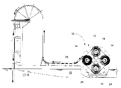
[0 0 010] FIG. 1 is an elevation view of the invention on a vessel.
[010011] FIG. 2 is a plan view of the invention on a vessel.
[00012] FIG. 3 is an enlarged view of item 3 in Fig. 2.
[00013] FIG. 4 is a side view of the invention without the product storage
reels.
[00014] FIG. 5 is an end view of the invention without the product storage
reels.
[00015] FIG. 6 is a side view of the invention with the product storage
reels.
[00016] FIG. 7 is an end view of the invention with the product storage
reels.
[00017] FIG. 8 is a side view of the invention on a vessel during laying
operation with two
of the product storage reels emptied.
[00018] FIG. 9 is a side view of the invention that illustrates rotation of
the cartridge reel to
place a product storage reel in position for laying product.
-2-

CA 02788806 2012-09-05
DESCRIPTION OF THE PREFERRED EMBODIMENTS
[00019] As seen in Fig. 1 and 6 - 8, the invention is generally indicated
by reference
numeral 10. Carousel product reel 10 is generally comprised of a cartridge
reel 12 and a
plurality of product reels 14, means 16 for holding the cartridge reel 12 in a
selected
position and rotating the cartridge reel 12 into a different position, and
means 18 for
selective, individual rotation of each of the product reels 14.
[00020] As seen in Fig. 2 - 5, the cartridge reel 12 is a relatively large
revolving structure
designed to receive multiple smaller standard product storage reels 14 that
hold a flexible
product such as cable or flexible pipe. The reels used on vessels for storing
and laying
rigid or flexible product typically can have a diameter as much as 11.4
meters. In the
embodiment shown the cartridge reel 12 is positioned vertically on the vessel
15 such that
the hub 17 that provides the central axis of rotation of the cartridge reel 12
is in a
horizontal plane. However, it should be understood that a horizontal reel
arrangement of
the invention may also be used.
[00021] As best seen in Fig. 5 and 7, the cartridge reel 12 is preferably a
hub and spoke like
structure to reduce weight and cost. A typical pipe or cable reel on a vessel
has sides with
a large enough diameter on each side of the hub or axle to receive as much
product as
possible and so that gear cogs on one or both sides will engage with one or
more drive
motors that are in a fixed position on the vessel.
[00022] Because the invention is configured to lay product stored on the
smaller product
reels 14, the cartridge reel 12 of the invention may be provided with
structural side
members 20 of a smaller diameter than those on a typical reel. The cartridge
reel 12 is
provided with a drive ring 22, best seen in Fig. 4, 5, and 7, that extends
circumferentially
from the structural side members 20 on one side of the cartridge reel 12 so as
to engage
with the drive motor 24 on the vessel to rotate and hold the cartridge reel 12
in a selected
position. One drive ring 22 should provide sufficient force to rotate the
cartridge reel 12
and hold it in position due to the reduced payload on the product reels 14 and
the fact that
each product reel 14 will have a separate drive mechanism for rotation
thereof. The drive
ring 22 and drive motor 24 are used in combination as the means 16 for holding
the
cartridge reel 12 in a selected position and rotating the cartridge reel 12
into a different
position.
-3-

CA 02788806 2012-09-05
[00023] The product reels 14 are typical storage reels used for flexible
product such as
cable or flexible pipe. Each product reel 14 is paired with means 18 for
selective rotation
and holding the reel 14 in place in the form of a reel drive head 26 that
locks into the
central core of the product reel 14. For ease of availability and use, the
reel drive head 26
is preferably a standard reel drive head as typically used in the offshore
industry.
[00024] In operation, product reels 14 are loaded at an onshore location
with product 28
such as cable or flexible pipe. The product reels 14 may be installed onto a
cartridge reel
12 at an onshore location so that the cartridge reel 12, filled with product
reels 14 having
product, is ready for lifting and installation onto a product laying vessel 15
in a single lift
as seen in Fig. 1. The product reels 14 may also be installed one at a time
onto a cartridge
reel 12 that is already installed on a vessel 15 while the vessel 15 is
offshore and for
replacement with full reels 14 for potentially continuous laying of product 28
while
offshore.
[00025] As seen in Fig. 1 ¨ 3, the cartridge reel 12 is moved so as to
position a product reel
14 for laying of the product 28. The product reel 14 is rotated by the reel
drive head 26
and the product 28 is guided by equipment on the vessel 15 for laying the
product 28 on
the sea floor. The cartridge reel 12 is held in position by the engagement of
the drive ring
22 and the drive motor 24 during the pay out of product 28 from the product
reel 14.
[00026] As seen in Fig. 8 the cartridge reel 12 is rotated to move another
full product reel
14 into position once the product 28 has been paid out from other product
reels 14. The
cartridge reel 12 may be rotated in either a clockwise or counterclockwise
direction.
[00027] As seen in Fig. 9, an empty product reel 14 may be removed from the
cartridge reel
12 for replacement with a full product reel 14. A crane or other lifting
arrangement on the
vessel 15 is used during product laying operations for removal and
installation of the
product reels 14 if additional product reels 14 are available on the vessel
15.
[00028] It should be understood that, while the drawings illustrate
equipment for vertical
lay of the product, equipment for horizontal lay of the product may also be
used.
[00029] The invention provides several advantages over the previously used
pipe and cable
laying reels.
[00030] The invention will allow the storage of more reels in a smaller
area/footprint.
[00031] The invention also allows multiple storage reels to be lifted for
installation onto, or
removal from, the laying vessel in a single lift of the main reel instead of
multiple smaller
lifts from a supply vessel.
-4-

CA 02788806 2012-09-05
[00032]
While specific embodiments and/or details of the invention have been shown and
described above to illustrate the application of the principles of the
invention, it is
understood that this invention may be embodied as more fully described in the
claims, or
as otherwise known by those skilled in the art (including any and all
equivalents), without
departing from such principles.
- 5 -

Representative Drawing
A single figure which represents the drawing illustrating the invention.
Administrative Status

2024-08-01:As part of the Next Generation Patents (NGP) transition, the Canadian Patents Database (CPD) now contains a more detailed Event History, which replicates the Event Log of our new back-office solution.

Please note that "Inactive:" events refers to events no longer in use in our new back-office solution.

For a clearer understanding of the status of the application/patent presented on this page, the site Disclaimer , as well as the definitions for Patent , Event History , Maintenance Fee  and Payment History  should be consulted.

Event History

Description Date
Time Limit for Reversal Expired 2018-09-05
Change of Address or Method of Correspondence Request Received 2018-01-12
Letter Sent 2017-09-05
Grant by Issuance 2014-08-05
Inactive: Cover page published 2014-08-04
Inactive: Final fee received 2014-05-21
Pre-grant 2014-05-21
Notice of Allowance is Issued 2014-01-30
Letter Sent 2014-01-30
Notice of Allowance is Issued 2014-01-30
Inactive: Q2 passed 2014-01-28
Inactive: Approved for allowance (AFA) 2014-01-28
Amendment Received - Voluntary Amendment 2013-11-14
Inactive: S.30(2) Rules - Examiner requisition 2013-10-11
Inactive: Report - QC failed - Minor 2013-09-26
Inactive: Cover page published 2013-04-07
Application Published (Open to Public Inspection) 2013-04-07
Inactive: IPC assigned 2013-01-29
Inactive: First IPC assigned 2013-01-29
Inactive: IPC assigned 2013-01-29
Inactive: Filing certificate - RFE (English) 2012-09-19
Letter Sent 2012-09-19
Application Received - Regular National 2012-09-19
Request for Examination Requirements Determined Compliant 2012-09-05
All Requirements for Examination Determined Compliant 2012-09-05

Abandonment History

There is no abandonment history.

Fee History

Fee Type Anniversary Year Due Date Paid Date
Request for examination - standard 2012-09-05
Application fee - standard 2012-09-05
Final fee - standard 2014-05-21
MF (patent, 2nd anniv.) - standard 2014-09-05 2014-09-02
MF (patent, 3rd anniv.) - standard 2015-09-08 2015-08-31
MF (patent, 4th anniv.) - standard 2016-09-06 2016-08-29
Owners on Record

Note: Records showing the ownership history in alphabetical order.

Current Owners on Record
J. RAY MCDERMOTT, S.A.
Past Owners on Record
LEE DAVID SCREATON
LELAND HARRIS, JR. TAYLOR
Past Owners that do not appear in the "Owners on Record" listing will appear in other documentation within the application.
Documents

To view selected files, please enter reCAPTCHA code :


To view images, click a link in the Document Description column. To download the documents, select one or more checkboxes in the first column and then click the "Download Selected in PDF format (Zip Archive)" or the "Download Selected as Single PDF" button.

List of published and non-published patent-specific documents on the CPD .

If you have any difficulty accessing content, you can call the Client Service Centre at 1-866-997-1936 or send them an e-mail at CIPO Client Service Centre.


Document
Description 
Date
(yyyy-mm-dd) 
Number of pages   Size of Image (KB) 
Description 2012-09-04 5 228
Drawings 2012-09-04 7 201
Abstract 2012-09-04 1 16
Claims 2012-09-04 2 48
Representative drawing 2013-02-11 1 15
Description 2013-11-13 5 224
Acknowledgement of Request for Examination 2012-09-18 1 177
Filing Certificate (English) 2012-09-18 1 156
Commissioner's Notice - Application Found Allowable 2014-01-29 1 161
Reminder of maintenance fee due 2014-05-05 1 111
Maintenance Fee Notice 2017-10-16 1 181
Correspondence 2014-05-20 1 49