Note: Descriptions are shown in the official language in which they were submitted.
CA 02789136 2012-08-07
WO 2011/096829 PCT/NZ2011/000015
1
A DEVICE TO ENHANCE THE TRACTION OF A TRACKED VEHICLE
FIELD OF THE INVENTION
This invention relates to a device for use with a continuous. track of a
tracked vehicle to
enhance the traction of the vehicle.
BACKGROUND
Continuous tracks are often used on -off-road vehicles to provide ground
contact and
traction for large vehicles. Standard continuous tracks are formed from a
number of rigid
track shoes that are joined to each other by hinges. Each track shoe typically
has one or
more ribs extending along the shoe to provide traction. Standard continuous.
tracks
provide traction in general situations. However, those standard tracks do not
provide
adequate traction on steeps slopes, or slopes that are slippery from mud,
water or ice. In
particular, those standard tracks do not provide adequate traction on steep or
slippery,
slopes for larger, heavier vehicles.
Typically, to increase the traction of atracked vehicle, additional traction
devices are
welded to the track. However, those traction devices can only be removed by
being cut
free, which can damage the track and/or the device. Welding the traction
devices to the
track and cutting the devices free from the track can be difficult and time
consuming.
There are a number of devices for use with the continuous track of a tracked
vehicle.
Examples of such devices are described in U.S Re 36,02 that describes a
detachable elastic
pad to protect a road surface from damage caused by a tracked vehicle; JP
2001233375 that
describes a padded shoe for a track belt; and NZ 511373 that describes an
elastic pad for a
crawler track shoe. The pads described in those documents are designed to
reduce damage
to the ground and would not provide good stability to a vehicle on a steep or
slippery
slope.
US 6,540,310 describes a grouser structure that provides traction and shock
absorption and
JP 2004058688 describes a detachable grouser for a track. Both those documents
describe
using fasteners that extend through the track, which can be awkward to
assemble if the
track is already installed on- a vehicle.
CA 02789136 2012-08-07
PCT/NZ2011 /000015
Received 06/12/2011
-2-
US 2004/0174068, US 2003/0184157, and US 2004/0140717 each describes a
detachable
grouser assembly for use with vehicles having continuous tracks. Those
documents
describe attaching the grousers with fasteners that extend through the track
shoe or with
chains that extend over the track shoe. As described above, attaching a
grouser assembly
with fasteners can be awkward if the track is already installed on a vehicle.
Attaching a
grouser assembly using a chain is not very secure and the assembly could be
ripped off
when the vehicle is used.
US 6,299,265 describes a replaceable tyre gripping system for an endless track
to extend the
life of a track. The system described in this document would not enhance the
traction of a
tracked vehicle.
In this specification where reference has been made to patent specifications,
other external
documents, or other sources of information, this is generally for the purpose
of providing a
context fox discussing the features of the invention. Unless specifically
stated otherwise,
reference to such external documents or such sources of information is not to
be
construed as an admission that such documents or such sources of information,
in any
jurisdiction, are prior art or form part of the common general knowledge in
the art.
It is an object of at least preferred embodiments of the present invention to
provide a
device to enhance the traction of a vehicle having a continuous track, and/or
to at least
provide the public with a useful choice-
SUMMARY OF THE INVENTION
In accordance with a first aspect of the present invention, there is provided
a device for use
with a continuous track of a tracked vehicle to enhance the traction of the
vehicle, the
device comprising.
an elongate body having an elongate direction and a ground contacting surface;
and
a releasable bracket for releasably securing the elongate body to the
continuous
track, the bracket comprising a bracket body, a first damping member extending
from the
X127129 2
AMENDED SHEET
IPEA/AU
CA 02789136 2012-08-07
PCT/NZ2011 /000015
Received 06/12/2011
-3-
bracket body, a second clamping member extending from the bracket body at an
angle
relative to the first clamping member, and a fastener;
wherein`the bracket is arranged such that fastening the fastener causes the
bracket body to
wedge the elongate body and the track shoe between the first clamping member
and the
second clamping member.
In one embodiment the bracket is arranged such that fastening the fastener
draws the
releasable bracket in the elongate direction of the elongate body and causes
the second
clamping member to draw the first clamping member towards the elongate body in
a
direction generally transverse to the elongate direction to releasably secure
the elongate
body to the continuous.
In one embodiment the bracket comprises a clearance aperture through which the
fastener
extends.
The term 'comprising' as used in this specification means 'consisting at least
in part of; that
is to say when interpreting statements in this specification which include
'comprising', the
features prefaced by this term in each statement all need to be present but
other features
can also be present. Related terms such as 'comprise and 'comprised' are to be
interpreted
in a similar manner.
The device may further comprise a fixed bracket that is fixed to the elongate
body. The
fixed bracket may be integrally formed with the elongate body. Alternatively,
the fixed
bracket may be formed as a separate component and fixed to the elongate body
by
fasteners, for example.
In one embodiment, the releasable bracket is arranged to releasably secure one
end of the
elongate body to one side of the continuous track and the fixed bracket is
arranged to
secure the other end of the elongate body to other side of the continuous
track. In an
alternative embodiment, the device may comprise two releasable brackets for
releasably
connecting the device to the shoe of the continuous track, and each releasable
bracket may
have the bracket body, the first clamping member, the second clamping member
extending
at an angle relative to the first clamping member, and the fastener.
x-zn2~_2
AMENDED SHEET
1PEA/AU
CA 02789136 2012-08-07
PCT/NZ2011 /000015
Received 06/12/2011
-4-
The first clamping member of the releasable bracket may comprise one or more
projections for engaging with a surface of the elongate body. The projections
maybe
circular stud(s). The circular stud(s) may extend(s) substantially
perpendicularly from the
bracket body. Alternatively, the projections may be ribs, plates, bosses, or
shoulders, for
eaarnple
The second clamping member may comprise a leg extending at an angle from the
bracket
body. The leg may be integrally formed with the bracket body.
The device may have additional ground contacting features to further enhance
the traction
of the device.
The ground contacting surface of the elongate body may have a generally
triangular cross-
sectional profile. The cross-sectional profile of the ground contacting
surface may be
substantially constant along the length of the elongate body. The elongate
body may be
substantially rigid.
In one embodiment, the elongate body is adapted to nest between ribs of a
track shoe of
the continuous track.
In one embodiment, the elongate body extends across the transverse length of
the track
shoe, from one end of the track shoe to the other end of the track shoe.
In accordance with a second aspect of the present invention, there is provided
a device for
use with a continuous track of a tracked vehicle to enhance the traction of
the vehicle, the
device comprising
an elongate body having a surface;
a bracket arranged to secure the elongate body to the continuous track; and
a plurality of rigid teeth operatively attached to the elongate body and
projecting
beyond the surface of the elongate body.
In one embodiment, the bracket comprises a ground engaging feature(s).
302129_2
AMENDED SHEET
IPEA/AU
CA 02789136 2012-08-07
PCT/NZ2011 /000015
Received 06/12/2011
-5-
In one embodiment, the elongate body enhances traction of the vehicle in the
running
direction of the track and the ground engaging feature(s) of the bracket
enhance(s) traction
of the vehicle in a direction transverse to the running direction of the
track.
In one embodiment, the device is releasably secured to the continuous track.
The elongate body is adapted to nest between ribs of a track shoe of the
continuous track.
The elongate body may nest between two side ribs of the track shoe and extend
over an
intermediate rib positioned between the two side ribs. When assembled with the
track
shoe, the elongate body may substantially fill the gap between the side ribs
and contacts the
side ribs. Akernatively, the elongate body may nest between two adjacent side
ribs. The
elongate member extends across the transverse length of the track shoe, from
one end of
the track shoe to the other end of the track shoe.
In one embodiment, the device comprises it releasable bracket for releasably
securing the
elongate body to the continuous track.
In one embodiment, the releasable bracket comprises a bracket body, a first
clamping
member, a second clamping member extending at an acute angle relative to the
first
clamping member, and a fastener, wherein the bracket is arranged such that
fastening the
fastener causes the bracket body to wedge the elongate body and the track shoe
between
the first clamping member and the second clamping member.
In one embodiment, the device further comprises a further bracket for
releasably securing
the elongate body to the other side edge of the continuous track, the further
bracket
comprising a bracket body.
In one embodiment, the further bracket is a fixed bracket that is permanently
fixed to the
elongate body. The fixed bracket may be integrally formed with the elongate
body.
Alternatively, the fixed bracket may be formed as a separate component and
fixed to the
elongate body by fasteners, for example.
3027121_2
AMENDED SHEET
IPEA/AU
CA 02789136 2012-08-07
PCT/NZ2011 /000015
Received 06/12/2011
-6-
The elongate body may be substantially rigid.
In one embodiment, the further bracket is a releasable bracket that is
releasably secured to
the elongate body.
In one embodiment, the bracket body/bodies forth a ground engaging feature(s).
In one embodiment, a top surface of the bracket(s) is a substantially planar
surface for
contacting the ground surface.
In one embodiment, a top surface of the bracket(s) has serrations or teeth for
contacting
the ground surface.
In one embodiment, the bracket(s) is/are positioned at the end(s) of the
elongate body.
The plurality of teeth may be evenly or unevenly spaced along the length of
the elongate
body.
In one embodiment, each of the teeth may have a generally chevron or inverted
V-shaped
ground engaging surface, when viewed from an end of the elongate body. Each of
the
teeth may have an abutment face for attaching the tooth to the elongate body.
The
elongate body may have a generally triangular or inverted V-shaped cross-
sectional profile
and the abutment face of each tooth may be a generally chevron or inverted V-
shaped face
generally corresponding to the profile of the elongate body.
In one embodiment, the teeth may have a generally chevron or inverted V-shaped
ground
engaging surface, when viewed from a side of the elongate body. The teeth may
be
separate parts or may be connected together to form a saw tooth-like part.
In one embodiment, each tooth may have a generally flat and horizontal ground
engaging
surface, when viewed from an end of the elongate body. Each tooth may have an
abutment face for attaching the tooth to the elongate body. The elongate body
may have a
generally triangular or inverted V-shaped cross-sectional profile and the
abutment face of
30271292
AMENDED SHEET
IPEA/AU
CA 02789136 2012-08-07
PCT/NZ2011 /000015
Received 06/12/2011
-7-
each tooth may be a generally chevron or inverted V-shaped face generally
corresponding
to the profile of the elongate body. Additionally, the track may have a
grouser extending
across the transverse length of the track shoe, from one end of the track shoe
to the other
end of the track shoe and the tooth may have a recess having a profile
corresponding to
the profile of the grouser. The grouser may have a substantially wedge-shaped
profile and
each tooth may have a corresponding wedge-shaped recess.
Each tooth may have a slot adapted to receive one or more additional ground
engaging
feature. The additional ground engaging feature(s) may be teeth. Those teeth
may have a
generally chevron or inverted V-shaped ground engaging surface, when viewed
from a side
of the elongate body. The teeth may be separate parts or may be connected
together to
form a saw tooth-like part.
In one embodiment, the releasable bracket is arranged to releasably secure one
end of the
elongate body to one side of the continuous track and the fixed bracket is
arranged to
secure the other end of the elongate body to other side of the continuous
track.
The second aspect may include any one or more features of the fast aspect
above.
In accordance with a third aspect of the present invention, there is provided
a combination
of a track shoe and at least one device of the first, second or third aspects
described above
secured to the track shoe.
The track shoe may comprise side ribs with a gap between the side ribs. The
elongate body
of the device may substantially fill the gap between the side ribs and contact
the side ribs
The track shoe may further comprise an intermediate rib positioned between the
two side
ribs. The elongate body may nest between two side ribs of the track shoe and
extend over
the intermediate rib. Alternatively, the elongate body may nest between two
adjacent ribs.
The elongate body may extend across the transverse length of the track shoe,
from one end
of the track shoe to the other end of the track shoe.
3027129
AMENDED SHEET
IPEA/AU
CA 02789136 2012-08-07
PCT/NZ2011/000015
Received 06/12/2011
The elongate body may be adapted to nest between ribs of a track shoe of the
continuous
track. The elongate body may nest between two side ribs of the track shoe and
extend over
an intermediate rib positioned between the two side ribs. The elongate body
may
substantially fill the gap between the side ribs and contacts the side ribs.
Alternatively, the
elongate body may nest between two adjacent side ribs. The elongate body
extends across
the transverse length of the track shoe, from one end of the track shoe to the
other end of
the track shoe.
The device may be releasably secured to the continuous track. The device may
further
comprise a releasable bracket for releasably securing the elongate body to the
continuous
track. The bracket may comprise a bracket body, a first clamping member, a
second
clamping member extending at an acute angle relative to the first clamping
member, and a
fastener, wherein the bracket is arranged such that fastening the fastener
causes the bracket
body to wedge the elongate body and the track shoe between the first clamping
member
and the second clamping member.
In one embodiment, the device further comprises a further bracket for
releasably securing
the elongate body to the other side edge of the continuous track. The further
bracket may
be a fixed bracket that is permanently fixed to the elongate body or may be a
releasable
bracket that is releasably secured to the elongate body. The fixed bracket may
be integrally
formed with the elongate body. Alternatively, the fixed bracket may be formed
as a
separate component and fixed to the elongate body by fasteners, for example.
The third aspect may include any one or more features of the first or second
aspects above.
In accordance with a fourth aspect of the present invention, there is provided
a
combination of a continuous track with at least one device of the first or
second aspects
described above secured to the track.
The fourth aspect may include any one or more features of the first, second or
third
aspects above.
1027127_2
AMENDED SHEET
IPEA/AU
CA 02789136 2012-08-07
PCT/NZ20 1 1 /0000 1 5
Received 06/12/2011
-9-
In accordance with a fifth aspect of the invention, there is provided a kit of
parts for
assembling a device for use with a continuous track of a tracked vehicle to
enhance the
traction of the vehicle, the kit of pans comprising7
an elongate body;
a bracket that is attachable to the elongate body to secure the elongate body
to the
continuous track and
a plurality of rigid teeth that are attachable to the elongate body.
In one embodiment, the teeth may have a generally chevron or inverted V-shaped
ground
engaging surface when assembled with the elongate body. Each of the teeth may
have an
abutment face for attaching the tooth to the elongate body. The elongate body
may have a
generally triangular or inverted V-shaped cross-sectional profile and the
abutment fact of
each tooth may be a generally chevron or inverted V-shaped face generally
corresponding
to the profile of the elongate body.
The teeth may be separate parts or may be connected together to form a saw
tooth-like
part.
In one embodiment, each tooth may have a generally flat and horizontal ground
engaging
surface, when viewed from an end of the elongate body. Each tooth may have an
abutment face for attaching the tooth to the elongate body. The elongate body
may have a
generally triangular or inverted V-shaped cross-sectional profile and the
abutment face of
each tooth may be a generally chevron or inverted V-shaped face generally
corresponding
to the profile of the elongate body. Additionally, the track may have a
grouser extending
across the transverse length of the track shoe, from one end of the track shoe
to the other
end of the track shoe and the tooth may have a recess having a profile
corresponding to
the profile of the grouser. The grouser may have a substantially wedge-shaped
profile and
each tooth may have a corresponding wedge-shaped recess. Each tooth may have
slots
adapted to receive additional ground engaging features. The additional ground
engaging
features may be teeth. Those teeth may have a generally chevron or inverted V-
shaped
ground engaging surface; when viewed from a side of the elongate body. The
teeth may be
separate parts or may be connected together to form a saw tooth-like part.
30271292
AMENDED SHEET
IPEA/AU
CA 02789136 2012-08-07
PCT/NZ2011 /000015
Received 06/12/2011
-10-
The kit may comprise a pair of brackets arranged to secure the elongate body
to the
continuous track. The pair of brackets may comprise a fixed bracket and a
releasable
bracket.
The releasable bracket may comprise a bracket body, a first clamping member, a
second
clamping member extending at an acute angle relative to the first clamping
member, and a
fastener, wherein the bracket is arranged such that fastening the fastener
causes the bracket
body to wedge the elongate body and the track shoe between the first clamping
member
and the second clamping member.
The fixed bracket may be fixed to the elongate body. The fixed bracket may be
integrally
formed with the elongate body. Alternatively, the fixed bracket may be formed
as a
separate component and fixed to the elongate body by fasteners, for example.
In one embodiment, the releasable bracket is arranged to releasably secure one
end of the
elongate body to one side of the continuous track and the fixed bracket is
arranged to
secure the other end of the elongate body to other side of the continuous
track.
To those skilled in the art to which the invention relates, many changes in
construction and
widely differing embodiments and applications of the invention will suggest
themselves
without departing from the scope of the invention as defined in the appended
claims. The
disclosures and the descriptions herein ate purely Illustrative and are not
intended to be in
any sense limiting. Where specific integers are mentioned herein which have
known
equivalents in the art to which this invention relates, such known equivalents
are deemed to
be incorporated herein as if individually set forth.
As used herein the term `(s)' following a noun means the plural and/or
singular form of
that noun.
As used herein the term `and/or' means `and' or `of, or where the context
allows both.
AMENDED SHEET
IPEA/AU
CA 02789136 2012-08-07
WO 2011/096829 PCT/NZ2011/000015
-11-
The invention consists in the foregoing and also envisages constructions of
which the
following gives examples only.
BRIEF DESCRIPTION OF THE DRAWINGS
The present invention will now be described by way of example only and with
reference to
the accompanying drawings in which:
Figure 1 is a perspective view of an embodiment of the device secured to a
continuous track of a vehicle;
Figure 2 is a perspective view of the device during assembly to the continuous
track, before the releasable bracket is secured to the continuous track;
Figure 3 is a side view of the releasable bracket and elongate body of the
embodiment device;
Figure 4 is an end view of the elongate body and a single shoe of the
continuous
track;
Figure 5 is _a partial side view of the fixed bracket and elongate body;
Figure 6 is a perspective view of the device, in which the releasable bracket
is
secured to the continuous track;
Figure 7 is a perspective view of an embodiment of the device having ground
engaging features;
Figure 8 is a perspective view of an embodiment of the device having
alternative
ground engaging features;
Figure 9 is a side. view of the alternative ground engaging features of Figure
8;
Figure 10 is a schematic perspective view of an embodiment of the device
having
further alternative ground engaging features;
Figure 11 is a cross-sectional view towards the releasable bracket end of the
device shown in Figure 10 secured to a track shoe, with the releasable bracket
not shown;
Figure 12 is a partial' perspective view from above of the releasable bracket
end of
the device shown in Figure 10, with the releasable bracket;
Figure 13 is a cross-sectional view towards the fixed bracket end of the
device
shown in Figure 10 secured. to a track shoe, with the fixed bracket not shown;
Figure 14 is a partial perspective view from above of the fixed bracket end of
the
device shown in Figure 10, with the track shoe not shown;
CA 02789136 2012-08-07
WO 2011/096829 PCT/NZ2011/000015
-12-
Figure 15 is a cross-sectional view of the device of Figure 10 showing a
ground
engaging feature positioned intermediate the releasable bracket end and the
fixed bracket
end of the device;
Figure 16 is a perspective view of the device of Figure 10 with a further
ground
engaging feature;
Figure 17 is a perspective view of the device of Figure 10 with yet another
ground
engaging feature; and
Figure 18 is a cross-sectional view of the device showing a feature that
locates the
device relative to a rib of the track shoe.
DETAILED DESCRIPTION OF EMBODIMENTS OF THE INVENTION
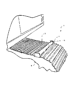
With reference to Figures 1 and 2, an embodiment of the device 1 for use with
a
continuous track 3 of a vehicle is shown. The device may be used on any
tracked vehicle
to enhance traction, such as a digger, bulldozer, snowmobile, crawler, or
tank, for example.
Unless otherwise specified, it should be appreciated that references to
directions in the
following description such as top, upper, lower, inverted or leading are for
reference only,
and should not be considered limiting.
The device 1 comprises a rigid elongate body 5 having a ground contacting
surface 6 and a
pair of brackets for releasably securing the elongate body 5 to the continuous
track 3. In
the embodiment shown, the pair of brackets comprises a releasable bracket 7
and a fixed
bracket 9. The brackets are rigid brackets.
With reference to Figure 3, the releasable bracket 7 has a bracket body 11 and
first
clamping members, in the form of two studs 13. In the embodiment shown, the
studs are
bolts that are welded to the bracket body. The studs extend generally
perpendicularly from
the bracket body. The releasable bracket 7 has a second clamping member in the
form of a
bracket leg 15. The bracket leg 1.5 extends .downwardly at an angle from the
bracket body
11 and at a non-parallel angle relative to the two studs 13. The angle is any
suitable angle.
In the embodiment shown, the angle is about 30 .
CA 02789136 2012-08-07
WO 2011/096829 PCT/NZ2011/000015
13-
The releasable bracket 7 has at least one fastener 17 extending through the
bracket body 11
into the elongate body 5. In the embodiment shown, the releasable bracket 7
has a pair of
fasteners 17. The fasteners extends through clearance slots 19 in the bracket
body 11 and
engages with corresponding threaded holes 21 formed in the elongate body 5.
The
fasteners are positioned in the lower part of the bracket body so that the
clamping force
provided by the fasteners is close to the track shoe.
With reference to figure 5, the fixed bracket is similar to the releasable
bracket, except that
it is permanently fixed to the elongate body 5. The fixed bracket has a
bracket body 25 and
10, a bracket leg 27 extending downwardly at an angle from the bracket body
25.
The device I has a pair of ground engaging features projecting beyond the
rigid surface of
the elongate body. In the embodiment shown, the ground engaging features are
formed by
a flat upper surface 29 of each bracket body. When assembled, the ground
engaging
features are positioned at the ends of the elongate body.
In an alternative embodiment, the upper surface 29 of the bracket may have
projections for
contacting the ground surface. For example, the top surface of the bracket may
have
serrations or teeth for contacting the ground surface. The elongate body
suitably enhances
traction of the vehicle in the running direction of the track and the ground
engaging
features suitably enhance traction of the vehicle in a direction transverse to
the running
direction of the track.
With reference to Figure 2, the elongate body 5 has a generally triangular
cross-sectional
profile and the ground contacting surface 6 has a corresponding generally
triangular cross-
sectional profile. In the embodiment shown, the cross-sectional profile of the
ground
contacting surface 6 is generally constant along the length of the elongate
body. In an
alternative embodiment, the ground contacting surface may comprise outwardly
extending,
features to further enhance the traction of the device. In a further
alternative embodiment,
the ground contacting surface may have any other suitable cross-sectional
profile, such as
an M-shape, for example. .
CA 02789136 2012-08-07
WO 2011/096829 PCT/NZ2011/000015
-14-
With reference to Figures 2 and 4, one end of the elongate body 5 has a side
plate 32
forming outwardly extending flanges 33. When, assembled, the studs contact the
outer
surfaces of the flanges. Alternatively, the elongate body 5 may be formed
without the
flanges and the studs could contact the ground contacting surface.of the
elongate body, for
example.
With reference to Figures 7 to 9, the device may be provided with one or more
ground
engaging feature(s) that project(s) beyond the surface of the elongate body 5.
In the
embodiment shown in Figure 7, the device comprises a plurality of ground
engaging
features, in the form of teeth 39. The teeth 39 are operatively attached to
the elongate
body 5. In the embodiment shown, the teeth 39 are attached directly to the
elongate body
5 by welding (not shown). Alternatively, the teeth 39 may be connected to the
elongate
body 5 via spacers or other components. The teeth 39 may be evenly or unevenly
spaced
along the length of the elongate body 5. Figure.9 is a side view of each of
the alternative
ground engaging features.
In the embodiment shown in Figure 7, the teeth have a generally chevron or
inverted V-
shaped ground engaging surface 41, when viewed from an end of the elongate
body. Each
of the teeth has an abutment face 42 for attaching the tooth to the elongate
body 5. The
abutment face 42 of each tooth is a generally chevron or inverted V-shaped
face generally
corresponding to the profile of the elongate body 5.
In the embodiment shown in Figure 8, the teeth 39 are generally triangular
components
that each has a generally chevron or inverted V-shaped ground engaging surface
41, when
viewed from a side of the elongate body. The teeth are connected together to
form a saw
tooth-like part. Alternatively, the teeth may be separate parts. Figure 9
shows a side view
of the saw tooth-like part.
In the embodiment shown in Figure 8, the teeth are integrally formed and have
an elongate
abutment surface 42b.for attaching the teeth 39 to the elongate body 5. The
device further
comprises braces 43 extending downwardly and outwardly from the teeth for
attaching the
teeth to the elongate body. The braces 43 extend from each side of the teeth
39. The teeth
may be attached to the elongate body by welding the abutment surface and the
braces 43 to
CA 02789136 2012-08-07
WO 2011/096829 PCT/NZ2011/000015
15-
the elongate body. Alternatively, the teeth 39 may be integrally formed with
the elongate
body 5.
Figures 7 and 9 show various profiles of the ground engaging surfaces of the
teeth 3.9. The
teeth may have a triangular ground engaging surface, indicated by reference
number 41 a.
Alternatively, the ground engaging surface may be formed with a protuberance,
indicated
by reference number-41b or with a notch 41c. Further, the ground engaging
surfaces may
be formed with further tread or rough surface to further improve the traction
of the
tracked vehicle with the device.
With reference to Figure 10, a further embodiment of the ground engaging
features is
shown. The ground engaging features shown _in Figure 10 are designed for use
with a
tracked vehicle in which the track shoes 3 have one or more grousers 45
extending across
the transverse length of the track shoe, from one end of the track shoe to the
other end of
the track shoe. Usually, those types of tracks are found on bulldozers.
With reference to Figures 10 and 11, the ground engaging features are in the
form of teeth
47 that extend laterally relative to the length of the elongate body 5. Each
tooth 47 has a
generally flat and.horizontal ground engaging surface 49, when viewed from the
end of the
elongate body. Alternatively, each tooth 47 may have any other suitable
profile, for
example, a triangular shaped profile. Figure 10 shows one tooth positioned at
the end of
the elongate body near the releasable bracket, one tooth positioned near the
fixed bracket,
and one intermediate tooth. It will be appreciated that the device may have
more or less
teeth, for example, two teeth or five teeth.
With reference to Figure 15, the intermediate tooth has an abutment face 51
for attaching
the tooth to the elongate body 5. The elongate body 5 has a generally
triangular or inverted
V-shaped cross-sectional profile and the abutment face 51 of the intermediate
tooth may
be a generally chevron or inverted V-shaped face generally corresponding to
the profile of
the elongate body. Additionally, when the track shoe has a grouser 45, the
tooth 47 has a.
corresponding recess 52 having a profile corresponding to the profile of the
grouser.
CA 02789136 2012-08-07
WO 2011/096829 PCT/NZ2011/000015
-16-
Figures 11 and 12 show a tooth 47 positioned near the releasable bracket end
of the
elongate body and Figures 13 and 14 show a tooth 47 positioned near the fixed
bracket end
of the elongate body. The teeth at the ends of the elongate body have a recess
52 having a
profile corresponding to the profile of the grouser. The end teeth do not have
an
abutment face with a profile corresponding to the profile of the elongate
body. However,
it will be appreciated that the teeth at the ends of the elongate body may
have that feature.
With reference to Figure 11, the tooth has clearance apertures 53 that the
studs of the
releasable bracket extend through, when the device is secured to a track shoe.
The
clearance apertures may be circular or oval shaped apertures. The grouser 45
has a
substantially wedge-shaped profile and each tooth 47 has a corresponding wedge-
shaped
recess 52. The leading portion 55 of the tooth 47 is relatively shorter on one
side of the
grouse than.the remainder of the tooth and has an upwardly tapered surface 57
to provide
clearance for the adjacent track shoe 3. The teeth 47 are rigid teeth. In the
embodiment
shown, the teeth 47 are formed from sheet or plate metal, preferably mild
steel. The teeth
are welded to the elongate body. Alternatively, the teeth may be integrally
formed with the
elongate body 5.
Each tooth 47 may have a slot 59 adapted to receive additional ground engaging
features.
The additional ground engaging features may be teeth 48 extending generally
parallel to.the
longitudinal axis of the elongate body, such as those shown in Figure 12.
Those teeth may
have a generally chevron or inverted V-shaped ground engaging surface, when
viewed from
a side of the elongate body, as shown in Figure 16. The teeth may be separate
parts or
may be connected together to form a saw tooth-like part. The teeth are
suitably welded to
the elongate bodies.
The additional ground engaging feature may have an upper flat surface, as
shown in Figure
17. The ground engaging feature shown in Figure 17 is an elongate, rigid
component 54,
which can be welded to the elongate body 5. The device may further have spikes
(not
shown) attached to the elongate body 54. Those spikes can be useful for icy or
snowy
conditions, for example.
CA 02789136 2012-08-07
WO 2011/096829 PCT/NZ2011/000015
-17-
With reference to Figure 18, the device may have one or more gussets 61 to
assist locating
and/or securing the device 1 to the track shoe 3. The gussets 61 are rigid
gussets. In the
embodiment shown, the gussets 61 are formed from sheet or plate metal,
preferably mild
steel. Each of the gussets 61 is substantially triangular in shape,
corresponding to the shape
of the elongate body 5. Each of the gussets 61 has a recess 63 that is adapted
to receive a
rib 3a of the track shoe. The size and shape of the recess 63 will be chosen
or designed
depending on the size and shape of the rib 3a. The gusset(s) 61 is/are welded
65 to the
elongate body 5. Alternatively, the gusset(s) may be integrally formed with
the, elongate
body.
-10
Figure 18 shows that a lower surface 67 of the gusset sits adjacent an upper
surface of the
track shoe 3, when the device .1 is installed on the track shoe.
Alternatively, the gusset.61
may extend only part way towards the upper surface of the track shoe so that
there is a gap
between the lower surface of the gusset and the upper surface of the track
shoe
The elongate body 5, brackets 7, 9 and teeth 39 may be formed from a suitable
metallic
material, such as mild steel. In the form shown, the elongate body 5 is formed
from a
single length of angle iron. The flanges may be formed from steel plate and
welded to the
end of the elongate body. The elongate body 5 also could be made out of two
pieces of
sheet.or plate material, which is then bent into shape and welded along the
top to form a
shape generally as shown. This method maybe required if a full angle iron is
not available
to suit the track shoe.
The brackets 7, 9. may be formed from steel plate and bent into the required
shape.
Alternatively, the brackets may be cast into the required shape. The studs. of
the releasable
bracket maybe formed by welding bolts or rods to the bracket body.
Alternatively, the
studs may be integrally formed as part of the bracket, for example, by casting
or forging the
bracket.
The fixed bracket 9 may be welded to the elongate body 5. Alternatively, the
fixed bracket
may be formed as a separate component that is fixed to the elongate body, for
example, by
fasteners. In another alternative, the elongate body and fixed bracket may be
formed as a
single integral component. .
CA 02789136 2012-08-07
WO 2011/096829 PCT/NZ2011/000015
-18-
To assemble the device to the track, the elongate body 5 is placed on the
track as shown in
Figures 2 and 4. The elongate body is adapted to nest between ribs of a rigid
track shoe of
the continuous track. The elongate body nests between two side ribs 3a of the
track shoe
and extends the transverse length of the shoe, between the side edges 3b of
the track.
Figure 4 shows the track shoe having a central rib 3c. In the embodiment
shown, the
elongate body has a clearance slot 35 allowing the elongate body to extend
over the central
rib 3c. The elongate body has further clearance slots 37 allowing the elongate
body to sit
over track fasteners.
When assembled with the track shoe, the elongate body substantially fills the
gap between
the side ribs and contacts the side ribs. Alternatively, the elongate body may
nest between
two adjacent side ribs. The elongate body extends across the transverse length
of the track
shoe, from one end of the track shoe to the other end of the track shoe.
With reference to Figure 2, the elongate body is placed on the track with the
leg 27 of the
fixed bracket positioned below the underside of the track. The releasable
bracket may be
loosely attached to the elongate body 5 before assembly to the track to
decrease the time
required to attach the device to the track, as shown in Figure 3.
Alternatively, the.
releasable bracket may not be attached to the elongate body 5 before the
device is placed
on the track, as shown in Figure 2.
When the fasteners 17 are tightened, the bracket body 11 and elongate body 5
are drawn
together in a generally horizontal direction. Fastening the fastener causes
the leg 15 to
25, engage with the underside of the track shoe and draw the studs 13 towards
the elongate
body to releasably secure the elongate body to the continuous track. As the
bracket body
11 and elongate body 5 are drawn together, the end of the elongate body and
the end of
the track shoe are wedged between the studs 13 and the leg 15 to secure the
elongate body
5 to the track 3. When secured, the studs contact the flanges 33 of the
elongate body 5
and the leg contacts the underside surface of the track shoe. The secured
bracket is shown
in Figure 6.
CA 02789136 2012-08-07
WO 2011/096829 PCT/NZ2011/000015
-19-
The clearance slots 19 formed in the bracket body allow the bracket to move
relative to the
elongate body 5 in the generally vertical direction as the fastener is
tightened.
Tightening the releasable bracket to the track will simultaneously cause the
fixed bracket
and the other end. of the elongate body, 5 to be drawn towards the
corresponding edge of
the track. That movement releasably secures the other end of the, elongate
body 5 to the
track. Due to the angle of the leg 27 that engages with the underside of the
track shoe, that
movement also pulls that end of the elongate body 5 down into secure
engagement with
the track shoe.
The device may be provided as a kit of parts for assembling the device for use
with a
continuous track of a tracked vehicle to enhance the traction of the vehicle.
The kit of .
parts may include the rigid elongate body 5 and a pair of brackets for
releasably securing
the elongate body.5 to the continuous track 3. The pair of brackets comprises
a releasable
bracket 7 and a fixed bracket 9, of the form described above.
The kit may comprise one or more ground engaging features, in the form of one
or more
teeth 39 that project beyond the surface of the elongate body when attached to
the
elongate body 5. The teeth have a generally chevron or inverted V-shaped
ground
engaging surface. Each of the teeth has an abutment face for attaching the
tooth to the
elongate body. The abutment face of each tooth is a generally.chevron or
inverted V-
shaped face generally corresponding. to the profile of the elongate body. The
teeth may be
separate parts or may be connected together to form a saw tooth-like part.
Alternatively, the device may be provided with the ground engaging features
connected to
the elongate body 5.
Over time, track shoes can become worn and the thickness of the track shoe can
decrease.
The relative angle between the leg and the studs allows the device to be used
on
continuous tracks having different track shoe thicknesses because the distance
between the
studs and the bracket leg can be adjusted to suit thinner tracks by tightening
the fastener
CA 02789136 2012-08-07
WO 2011/096829 PCT/NZ2011/000015
-20-
In use, more than one device would be used on the continuous track. For
example, a
continuous track may have about five or six devices along the track, spaced
about one
metre apart. The number of devices used on a track can be chosen depending on
the
traction required for any particular situation.
The device may also be useful in situations where the vehicle is stuck, such
as in very
muddy situations. One end of a chain. can be attached to the device 1 and the
other end
can be secured. The vehicle can then be driven forward by the vehicle pulling
on the chain.
The device 1 can be removed by loosening the fastener 17, which will release
the releasable
bracket and the fixed bracket from the track. The elongate body 5 can then be
removed
from the track.
Embodiments of the invention have been described by way of example only and
. modifications may be made thereto without departing from the scope of the
invention.
For example, in one alternative embodiment, the bracket leg may extend
generally
perpendicularly from the bracket body and the studs may extend at a non-
perpendicular
angle relative to the bracket body. In another alternative embodiment, the
bracket leg and
studs may extend at non-perpendicular angles relative to the bracket body. .
In the embodiment shown, the first clamping member is defined by two studs.
Alternatively, the first clamping member may be formed by any other suitable.
protrusion(s), such as ribs, plates, bosses or shoulders, for example. .
For example, the ground-contacting surface may be formed with a textured
surface and/or
outwardly extending features to further enhance the traction of the device and
the
continuous track.
For example, the ground engaging features have been described as teeth having
triangular
or chevron shaped components. Alternatively, the teeth may have any other
suitable shape,
such as rectangular, or square, for example. Those alternative shapes may also
be formed
with notches or projections as described above in relation to the triangular
shaped teeth.
CA 02789136 2012-08-07
WO 2011/096829 PCT/NZ2011/000015
-21 -.
It.will -be appreciated that the device may a multi-fit device that may be
used for different
tracked vehicles. Such a multi-fit device may be narrower, for example, to fit
the various
different types of tracks, or have features that allow the device to be
positioned on or
adjacent a grouser of a track shoe.
Other alternatives to the embodiments described are set out in the `Summary of
the
Invention' section.