Note: Descriptions are shown in the official language in which they were submitted.
CA 02789832 2016-08-18
1
Safety brake device for moving machine elements
The invention relates to a safety brake device for moving
machine elements designed to prevent injuries to the extremities
of the operator of a machine, and more particularly to a safety
brake device for moving machine elements to prevent injury to
the extremities of the operator of a machine if the distance of
said operator from the moving machine element is less than a
defined safety area.
A number of safety devices are already known which are
intended to reduce the danger of accidents to the operator from
moving machine elements such as tools, blades, presses or
similar where the workpieces are fed or removed manually.
These safety devices are in most cases very simple in
design and do not offer full protection for the operator, since
these only protect parts of the machine elements or tools, or
the machine elements have a relatively long stopping time and it
is thus still possible to reach into the hazardous area.
Most of the safety devices currently known consist of
separating mechanical safety covers which partially cover the
hazardous areas, or emergency stop devices which cut off the
energy supply and are tripped manually or through contact with
switching devices. Nonetheless, a considerable residual hazard
remains since, due to their rotary or kinetic energy, the moving
machine elements are not stopped immediately. Even though the
drives of the machines are increasingly equipped with brakes,
the stopping times in each case amount to several seconds, which
means that injuries cannot be prevented.
A safety device is also already known in which the saw
blade of a circular saw is brought to a standstill in the event
of an emergency by means of an aluminium claw. However, a
disadvantage here is that the aluminium claw needs to be
replaced after each use.
In order to eliminate the disadvantages described, the
invention is therefore based on the problem of creating a safety
brake device for moving machine elements which can be used
CA 02789832 2016-08-18
2
universally and is of simple construction, which is easy to
maintain and at the same time offers a greater protective effect
for the operator than the previously known safety and protection
devices.
This problem is solved by the invention through the
features described herein.
According to one aspect of the present invention, there is
provided a safety brake device for moving machine elements to
prevent injury to the extremities of the operator of a machine
if the distance of said operator from the moving machine
element is less than a defined safety area, characterised by
a) an arrangement for detecting the operator's position,
in order to permit operation of the machine only if the operator
remains within the defined working area, wherein the arrangement
for detecting the operator's position features a transponder
worn, directly or indirectly, by the operator, for example by
means of an article of clothing,
b) an arrangement for detecting the position of the
operator's extremities within a predefined safety zone which
enables the required work activities to be performed, wherein
the arrangement for detecting the position of the operator's
extremities features photoelectric sensors, laser scanners or
similar which are attached to the machine, and
c) a brake device by means of which the moving machine
element can be immediately stopped if the operator's extremities
go beyond the safety area, wherein the brake device features a
brake calliper which acts on the moving machine element by means
of a control.
Advantageous embodiments thereof are described herein.
According to another aspect of the present invention,
there is provided a safety brake device as described herein,
characterised in that the control for the brake device (5)
functions electrically or electronically.
According to yet another aspect of the present invention,
there is provided a safety brake device as described herein,
characterised in that the brake calliper (5) is electrically
CA 02789832 2016-08-18
,
,
3
operable.
According to still another aspect of the present
invention, there is provided a safety brake device as described
herein, characterised in that the brake calliper is
hydraulically operable.
According to a further aspect of the present invention,
there is provided a safety brake device as described herein,
characterised in that the brake calliper is pneumatically
operable.
According to yet a further aspect of the present
invention, there is provided a safety brake device as described
herein, characterised in that the brake calliper is mechanically
operable.
According to still a further aspect of the present
invention, there is provided a safety brake device as described
herein, characterised in that it is activated automatically each
time the machine is started.
According to another aspect of the present invention,
there is provided a safety brake device as described herein,
characterised in that the machine is shut down as soon as the
operator leaves the defined working area.
According to yet another aspect of the present invention,
there is provided a safety brake device for moving machine
elements to prevent injury to the extremities of the operator
of a machine if the distance of said operator from the moving
machine element is less than a defined safety area,
characterised by
a) an arrangement for detecting the operator's position,
in order to permit operation of the machine only if the operator
remains within the defined working area,
b) an arrangement for detecting the position of the
operator's extremities within a predefined safety zone which
enables the required work activities to be performed, and
c) a brake device by means of which the moving machine
element can be immediately stopped if the operator's extremities
go beyond the safety area.
CA 02789832 2016-08-18
,
,
4
According to still another aspect of the present
invention, there is provided a safety brake device as described
herein, characterised in that the arrangement for detecting the
operator's position features a transponder worn, directly or
indirectly, by the operator, for example by means of an article
of clothing.
According to a further aspect of the present invention,
there is provided a safety brake device as described herein,
characterised in that the arrangement for detecting the position
of the operator's extremities features photoelectric sensors,
laser scanners or similar which are attached to the machine.
According to yet a further aspect of the present
invention, there is provided a safety brake device as described
herein, characterised in that the brake device features a brake
calliper which acts on the moving machine element by means of a
control.
According to still a further aspect of the present
invention, there is provided a safety brake device as described
herein, characterised in that the control for the brake device
functions electrically or electronically.
According to another aspect of the present invention,
there is provided a safety brake device as described herein,
characterised in that the brake calliper is electrically
operable.
According to yet another aspect of the present invention,
there is provided a safety brake device as described herein,
characterised in that the brake calliper is hydraulically
operable.
According to still another aspect of the present
invention, there is provided a safety brake device as described
herein, characterised in that the brake calliper is
pneumatically operable.
According to a further aspect of the present invention,
there is provided a safety brake device as described herein,
characterised in that the brake calliper is mechanically
operable.
CA 02789832 2016-08-18
,
,
According to yet a further aspect of the present
invention, there is provided a safety brake device as described
herein, characterised in that it is activated automatically each
time the machine is started.
5 According to still a further aspect of the present
invention, there is provided a safety brake device as described
herein, characterised in that the machine is shut down as soon
as the operator leaves the defined working area.
Numerous significant advantages are achieved through the
safety brake device according to the invention in comparison
with the prior art.
For example, the safety brake device according to the
invention contains few or no parts subject to wear, so that
hardly any maintenance work is required and maintenance costs
are reduced accordingly.
The invention also prevents a machine remaining in
function when no operator is present in the working area.
Finally, the operator's extremities are prevented from reaching
the moving machine element, since this is stopped immediately
through a brake device acting directly on the moving machine
element. This makes it possible to reduce the stopping times of
the moving machine elements to almost zero and thus prevent any
injury to the operator.
Incidentally, the term operator's extremities is
understood to mean their legs and, in particular, their arms.
Naturally, it is also possible to provide an arrangement such
that all of the operator's body parts are identified in such a
way that they are relevant for the moving machine elements.
The invention possesses an, in particular person-side,
detection system through which the position of the operator is
detected. Transponders of a usual design can be used for this
purpose, being for example incorporated in the gloves, but also
in other articles of clothing which the operator has to wear
when working on the machine, or also being worn by the operator
on their body in another form.
The invention also possesses a, in particular machine-
CA 02789832 2016-08-18
6
side, detection system for the position of the operator's
extremities. This identifies the position of the operator's
extremities in relation to the moving machine elements in order
to prevent the operator's extremities coming into contact with
the moving machine elements and suffering an injury.
Photoelectric sensors, laser scanners or other known systems
can, for example, be used for this purpose.
If the operator's extremities pass or intrude into the
safety area thus defined, the detection system is activated and
the moving machine element is brought to a stop directly by
means of a brake device, preferably in the form of a brake
calliper. This prevents the operator from being injured.
The brake calliper is attached in such a way that it acts
indirectly or directly on the moving machine element.
Consequently, the stopping times or stopping travel distances
are virtually zero, and in any case are so small that there is
no possibility of the operator injuring themselves.
If the emergency braking is initiated because, for
example, the operator's hands have crossed the safety area, the
brake calliper is closed and the moving machine element is
brought to a stop.
The brake calliper is actuated by means of a control
module, which also evaluates the position recognition
information, and at the same time the energy supply to the
machine is interrupted or enabled.
No complicated resetting of the safety device by the
operator is necessary. This takes place when the machine is
switched on.
According to one aspect of the present invention, there is
provided, a safety brake device for moving machine elements to
prevent injury to the extremities of an operator of a machine
for a distance of said operator from the moving machine element
less than a predefined defined safety zone, comprising: a
transponder worn, directly or indirectly, by the operator in an
arrangement for detecting the operator's position, and permit
operation of the machine only if the operator remains within a
CA 02789832 2016-08-18
7
defined working area and shut down the machine as soon as the
operator leaves the defined working area; photoelectric sensors
or laser scanners attached to the machine in an arrangement for
detecting the position of the operator's extremities within the
safety zone which enables the required work activities to be
performed; and a control module acting on a brake caliper of
said safety brake device, said control module configured to
determine that the operator's extremities go beyond the safety
zone based on signals from the photoelectric sensors or laser
scanners, and to function electrically or electronically to
immediately stop the moving machine element when the operator's
extremities go beyond the safety zone, and interrupting or
enabling energy supply to said machine.
According to another aspect of the present invention,
there is provided a safety brake device as described herein,
wherein the brake caliper is electrically operable.
According to yet another aspect of the present invention,
there is provided a safety brake device as described herein,
wherein the brake caliper is hydraulically operable.
According to still another aspect of the present
invention, there is provided a safety brake device as described
herein, wherein the brake caliper is pneumatically operable.
According to a further aspect of the present invention,
there is provided a safety brake device as described herein,
wherein the brake caliper is mechanically operable.
According to yet a further aspect of the present
invention, there is provided a safety brake device as described
herein, wherein said safety device is activated automatically
each time the machine is started.
According to still a further aspect of the present
CA 02789832 2016-08-18
,
,
8
invention, there is provided a safety brake device for moving
machine elements to prevent injury to the extremities of the
operator of a machine when the distance of said operator from
the moving machine element is less than a defined safety area,
comprising: a first detector arranged for detecting the
operator's position, in order to permit operation of the machine
only if the operator remains within the defined working area and
shut down the machine as soon as the operator leaves the defined
working area; a second detector arranged for detecting the
position of the operator's extremities within a predefined
safety zone which enables the required work activities to be
performed; a brake device capable of immediately stopping the
moving machine element if the operator's extremities go beyond
the safety area; and a control module for controlling said brake
device, said control module; determining the position of the
operator based on signals from the first detector; determining
the position of the operator's extremities based on signals from
the second detector: permitting the machine to function when the
operator is present in the working area; interrupting the energy
supply to the machine; immediately stopping said moving machine
element as soon as the operator leaves the working area; and/or
immediately stopping said moving machine element and
interrupting said drive energy as soon as the operator's
extremities pass the safety area.
According to another aspect of the present invention,
there is provided a safety brake device as described herein,
wherein the first detector includes a transponder for detecting
the operator's position, said transponder worn, directly or
indirectly, by the operator.
According to yet another aspect of the present invention,
there is provided a safety brake device as described herein,
wherein the second detector includes photoelectric sensors or
laser scanners, attached to the machine, for detecting the
position of the operator's extremities.
CA 02789832 2016-08-18
9
According to still another aspect of the present
invention, there is provided a safety brake device as described
herein, wherein the brake device includes a brake caliper which
acts on the moving machine element by a control.
According to a further aspect of the present invention,
there is provided a safety brake device as described herein,
wherein the control module for the brake device functions
electrically or electronically.
According to yet a further aspect of the present
invention, there is provided a safety brake device as described
herein, wherein the brake caliper is electrically operable.
According to still a further aspect of the present
invention, there is provided a safety brake device as described
herein, wherein the brake caliper is hydraulically operable or
pneumatically operable.
According to another aspect of the present invention,
there is provided a safety brake device as described herein,
wherein the brake caliper is mechanically operable.
According to yet another aspect of the present invention,
there is provided a safety brake device as described herein,
including an activation module for automatic activation each
time the machine is started.
According to still another aspect of the present
invention, there is provided a safety brake device for moving
machine elements to prevent injury to the operator of a machine,
comprising: an arrangement for detecting the position of the
operator's extremities within a safety area, wherein the
arrangement detects the position of the operator, in order to
permit operation of the machine only if the operator remains
CA 02789832 2016-08-18
,
within a defined working area in which the machine can be fed
with work pieces or work pieces can be removed from the machine,
wherein the machine is shut down as soon as the operator leaves
the working area; a brake device for immediately stopping the
5 moving machine element if the operator's extremities go beyond
the safety area; and a control module for controlling said
safety brake device, said control module; determining the
position of the operator's extremities and the position of the
operator based on signals from the arrangement; permitting the
10 machine to functions when the operator is present in the working
area; immediately stopping said moving machine element as soon
as the operator leaves the working area by interrupting the
energy supply or drive energy to the machine; and/or immediately
stopping said moving machine element and interrupting said drive
energy as soon as the operator's extremities pass the safety
area.
The invention is explained in more detail in the following
with reference to the drawing, in which:
Fig. 1 shows, in diagrammatic form, the safety brake
device according to the invention in combination with a circular
saw, viewed from the side and
Fig. 2 as viewed from the front.
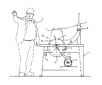
The illustrated embodiment shows the application of the
safety brake device according to the invention on the circular
saw blade of a circular bench saw, in order to prevent the
operator from being able to come into contact with the saw blade
with their extremities, in the present case with their hands.
Specifically, the circular saw is equipped with a machine
frame 1 in which an electric motor 2 is arranged which is
connected with the drive of the circular saw blade 4 via a belt
drive 3.
As shown, a brake calliper 5 is provided below the actual
working area of the circular saw blade 4, i.e. in the present
case beneath the workbench, which can, via a suitable control,
act directly on the circular saw blade 4 in such a way that this
is brought to a stop within fractions of a second.
CA 02789832 2016-08-18
11
As can also be seen from the drawing, safety sensors 6 and
sensors 7 for presence monitoring are also provided.
A control cabinet 8 contains the necessary controls,
whereby it is possible to switch the entire machine on and off
by means of a main switch 9.
The circular saw blade 4 is provided in a usual manner
with a movable safety cover 10 as well as a fixed safety cover
11 on the bottom (see Fig. 2).
The belt drive 3 driven by the electric motor 2 acts on
the actual drive 12 of the circular saw blade 4, as can clearly
be seen from Fig. 2.
An operator 13 wearing, in the manner described above, a
device, not represented in detail, for detection of their
position, for example a transponder sown into the operator's
glove, can work without hindrance within the vicinity of the
circular saw blade 4 outside of the safety area 14 monitored by
the safety sensors 6. However, if they move their hands into
this safety area 14, the brake calliper 5 is immediately
actuated through a corresponding control which, as described,
acts on the circular saw blade 4 within fractions of a second
and brings this completely to a stop.
In the following it will be described once again how the
safety system shown is structured:
1. Arrangement for detecting the position of the operator
13, for example by means of a transponder or similar device,
which only makes it possible to put the machine into operation
when the operator 13 is present within the defined proximity or
operating area of the machine. This ensures that the machine
does not remain in operation when not supervised.
2. Arrangement for detecting the position of the
operator's extremities 13 within a predefined safety zone which
allows the working operations, that is to say the feeding and
removal of the workpieces, to be performed.
Reflective materials from which gloves for the operator
are manufactured can, for example, be used for this purpose. In
order to detect the position of the hands, photoelectric sensors
CA 02789832 2016-08-18
12
can be used which are positioned on the machine and so create a
defined working area within which the operator can move his
hands without danger. Other systems suitable for this purpose,
such as optoelectric scanners, laser devices, transponder
systems or similar, can also be used in order to detect the
position of the operator's extremities.
3. Brake device which acts directly on the saw blade, thus
bringing the saw blade immediately to a stop, as soon as the
extremities leave the defined safety area, that is to say when
the extremities approach too close to the saw blade or if the
operator leaves the working area.
The brake device preferably consists of a brake calliper
5, which can be actuated electromechanically, pneumatically,
hydraulically, purely through spring force or through another
form of energy.
The brake device is arranged in such a way that the
working area is not restricted; in the case of the circular saw,
for example, below the working level and thus covered by the
workbench. This brake device can be used in combination with the
electromechanically braked drives provided on most machines.
4. Electronic or electric control with the following
functions:
a) only to permit the machine to function when the
operator is present in the working area; the energy supply to
the machine is interrupted for this purpose;
b) control for the brake device, through which the saw
blade 4 is immediately stopped and the drive energy interrupted
as soon as the operator 13 leaves the working area;
c) control for the brake device, through which the saw
blade 4 is immediately stopped and the drive energy interrupted
as soon as the operator's extremities 13 pass the safety zone
14.
The use of the described safety brake device makes it
possible to provide the operator and in particular his
extremities with the best possible protection during all working
operations and in this way prevent accidents. In addition, the
CA 02789832 2016-08-18
13
machine is shut down as soon as the operator leaves the defined
working area, which means that the machine does not remain in
function when not supervised and no other persons are endangered
unnecessarily.
Should the operator come too close to the hazardous moving
machine element, for example the circular saw, this is stopped
immediately, so that no injuries are possible.
The simple construction design allows the total system to
be built into all machines or also fitted subsequently, whereby
a wide variety of technical solutions for detecting the position
of the operator or his extremities are possible.
Regarding features of the invention not described in
detail above, express reference is made to the description and
the claims.