Note: Descriptions are shown in the official language in which they were submitted.
CA 02790015 2012-08-15
MULTI-ZONE HEATING SYSTEM
BACKGROUND
[0003] This invention is directed at a heating system. In particular, this
invention is directed
at a heating cabinet with the capacity for multiple heating zones.
[0004] Heating cabinets are frequently used to warm items and maintain the
items at a
desired temperature for a period of time. Conventionally, heating cabinets
include an interior
chamber which is accessible via a door. Internal heating elements warm the
items inside the
chamber. To best utilize the volume of the chamber, there are often shelves or
other fixtures to
accommodate placement of items vertically within the cabinet.
[0005] These warming cabinets are employed across a wide number of industries.
For
example, in the food service industry, once food has been prepared, the
prepared food may be
kept warm for a length of time before the food is served. Warming cabinets
provide convenient,
and frequently transportable, storage for the prepared food. As another
example, in the medical
industry, heating cabinets are frequently used to maintain intravenous fluids
at or near body
temperature to maintain the quality of the fluids and to prevent the receiving
body from entering
a state of thermal shock upon introduction of the intravenous fluid.
-1-
CA 02790015 2012-08-15
WO 2011/103136 PCT/US2011/025006
[0006] However, there are a number of challenges in
making and using cabinets of this type. For one, when
items are placed within the internal chamber, the
cabinets may have an uneven item load. This can result
in internal thermal gradients and uneven warming of the
items in the cabinet. Additionally, production and/or
maintenance of these cabinets may be time consuming or
costly. Depending on the particular cabinet, specific
parts may need to be stocked or ordered for different
cabinet models.
[0007] Hence, a need exists for an improved heating
cabinet with a flexible construction that is also easily
assembled.
SUMMARY OF THE INVENTION
[0008] The present invention provides a heating system
with a flexible construction that is easily assembled.
The disclosed heating system may be adapted to include a
number of heating elements which may be attached at
various locations around a cabinet. These heating
elements are universally connectable to a controller
which independently monitors the temperature of the zone
corresponding to each of the heating elements and
compensates for the load variations across the cabinet.
Additionally, if the heating elements fail, then the
heating elements are also easily replaceable given their
attachment configuration.
(000 ] According to one aspect, a heating system is
disclosed including a cabinet having walls defining an
interior heating chamber. Two or more sensors are
attached to an exterior surface of the walls and two or
more heating pad subassemblies are attached to the
exterior surface of the walls. Each of the heating pad
subassemblies are located adjacent a corresponding sensor
and include a pad coupled to the exterior surface of the
walls and a heating element coupled to the pad. A
controller is in electrical communication with the
_. 2 -
CA 02790015 2012-08-15
WO 2011/103136 PCT/US2011/025006
heating elements and the sensors. This controller is
configured to independently monitor temperature
measurements from each of the sensors and. that is further
configured to independently control each of the heating
elements, The heating pad subassemblies are positionable
on the exterior side of the walls and the heating system
compensates for load variations across the interior
heating chamber
(00101 In. one form of attachment, the heating pad
subassembly or subassemblies may further include openings
formed there through and the heating system may further
comprise a plurality of couplings including coupling
first portions disposed on the exterior surface of the
walls and coupling second portions coupled to the
coupling first portions. At least a portion of the
couplings may extend through the openings in the heating
pad subassembly, thereby coupling the heating pad
subassembly to the cabinet. The coupling first portions
may be pins and. the coupling second portions may be.
retaining clips. If the coupling first portions are
pins, the pins may be welded to the walls.
(00111 The heating system may further include
insulation, such as, for example, rigid fiberglass
insulation, and the couplings may extend through the
insulation, thereby also coupling the insulation to the
cabinet. In this form, the coupling second portions may
engage an outwardly facing surface of the insulation.
This may result in the heating pad subassembly being
sandwiched between the exterior surface of the wall(s) of
the cabinet and the insulation.
(00121 In another form of attachment, the heating pad
subassemblies may be adhesively attached to the exterior
surface of the walls of the cabinet. This may be apart
from or in addition to any mechanical means of
attachment.
_ 3 -
CA 02790015 2012-08-15
WO 2011/103136 PCT/US2011/025006
[0013] The heating pad subassemblies may, include an
electrical connector for connecting the heating pad
subassemblies to the controller. The heating pad
subassemblies may include a circuit which. allows the
heating pad subassemblies to operate on 120 volt or 230
volt power.
[0014] Each of the sensors may include an electrical
connector for connecting the sensors to the controller.
The heating pad subassembly may further include a sensor
aperture formed through the pad that is adapted for
placement over one of the sensors such that, when one of
the heating pad subassemblies is placed over the sensor,
the electrical connector for connecting the sensor to the
controller remains exposed. The sensor aperture may be
centrally disposed on the heating pad subassembly. The
sensor may be attached to the exterior surface of the
walls via. a bracket and the sensor aperture formed
through the pad may be sized to match the bracket:
[0015] Alternatively, the sensor may be embedded in.
the heating pad subassembly, With this construction, the
sensor is automatically located relative to heating pad
subassembly, regardless of the exact placement of the
heating pad subassembly on the heating system. Although
this construction may make it more difficult to access
the sensor for repair, there may be cost savings
associated with assembling the heating system when the
sensor is embedded in the heating pad subassembly.
[0016] The heating element may be a thermal cable and
may be electrically resistive. In one form, the heating
pad subassembly may be a silicone heated pad.
[0017] A method of making a. heating system is also
disclosed. A cabinet is provided having walls defining
an interior heating chamber. Coupling first portions are
attached on the exterior surface of the walls. A heating
pad subassembly is placed on an exterior surface of the
walls of the cabinet in which the heating- pad subassembly
4 -
CA 02790015 2012-08-15
WO 2011/103136 PCT/US2011/025006
includes a heating element and a openings are formed
through the heating pad subassembly. Coupling second
portions are coupled to the coupling first portions to
form a plurality of couplings. At least a portion of the
couplings extend through the openings in the heating pad
subassembly, thereby coupling the heating pad subassembly
to the cabinet,
[0018] The method may further include the step of
placing insulation on the heating pad subassembly before
coupling a plurality of coupling second portions to the
plurality of coupling first portions. Doing this can
sandwich the heating pad subassembly between the exterior
surface of the cabinet and the insulation.
[0019] In still other forms, the method may include
the step of attaching a. sensor to an exterior surface of
the walls. In this case, the heating pad subassembly may
further have a sensor aperture formed there through that
is adapted to receive the sensor such that, when the
heating pad subassembly is placed over the sensor, the
sensor is accessible from a. back side of the heating pad
subassembly.
[0020] Tn stil]. other forms, the heating element may
be affixed with an adhesive
[0021] In still other forms, the heating element may
be affixed with a rigid plate that has a plurality of
couplings.
[0022] in some forms, there may be a. plurality of
heating pad subassemblies and a corresponding plurality
of sensors. In such cases, the method may further include
the step of placing a controller in electrical.
communication with the heating elements and the sensors.
This controller may be configured to independently
monitor temperature measurements from each of the sensors
and may further be configured to independently control
each of the heating elements. This arrangement can
assist in maintaining the temperature over the volume of
- 5 -
CA 02790015 2012-08-15
WO 2011/103136 PCT/US2011/025006
the interior heating chamber even when uneven loads to be
heated occupy the volume.
[0023] in some forms, the plurality of coupling first
portions may be pins and the plurality of coupling second
portions may be retaining clips. The method may further
include the step of welding the pins to the walls.
[0024] Thus, this invention allows for more flexible
construction and easier assembly of heating systems.
Depending on the size and configuration of the cabinet,
the heating pad subassemblies may be placed at various
locations on the cabinet. As these heating pad
subassemblies, and their corresponding sensors, are
independently controlled and monitored, regardless of the
exact placement and number of the pads, the controller is
i5 capable of operating the heating system so as to reduce
thermal gradients that result from uneven load
distribution. Particularly when the cabinet is made-to-
order, this heating system accommodates various
constructions with little or no modification to the basic
heating components.
[0025] The disclosed heating system may also utilize
common components across various models or sizes of
cabinets, meaning that there is less need to have
customized parts in the cabinet. For example, the same
type of heating pad subassembly may be used in various
sizes of cabinets (although larger volume cabinets may
require more heating pad subassemblies to adequately heat
the larger volume). Further, the controller may be
configured to be operable in any of a number of different
cabinets without the need to specifically program the
controller based on the specifications of the heating
cabinet. Programming controllers is a significant and
time consuming part of construction and repair of heating
systems.
[0026] These and still other advantages of the
invention will be apparent from the detailed description
- 6 -
CA 02790015 2012-08-15
WO 2011/103136 PCT/US2011/025006
and drawings. What follows is merely a description of the
preferred embodiments of the present invention. To
assess the full scope of the invention the claims should
be looked to as the preferred embodiments are not
intended to be the only embodiments within the scope of
the claims.
BRIEF DESCRIPTION OF THE DRAWINGS
[0027] FIG. 1 a perspective view of a heating system;
[0028] FIG, 2 is a schematic illustrating the
connectivity of the various components of the heating
system;
[0029] FIGS. 3 through 5 illustrate the steps of
assembling a heating system in which a heating pad
subassembly and insulation is attached using mechanical
couplings; and
(0030] FIG. 6 is a cross-sectional side view taken
through line 6-6 of FIG, 5.
DETAILED DESCRIPTION OF THE PREFERRED EMBODIMENTS
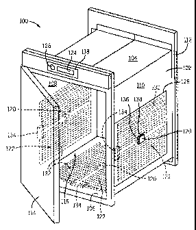
(00311 Referring first to FIG. 1, a heating system 100
is shown. The heating system 100 may be used to warm
items for a variety of applications. Some examples of
items that may be heated include, but are not limited to,
blankets, intravenous fluids, and food products.
[0032] The heating system 100 includes a cabinet 102
having a plurality of walls including a top wall 104, a
bottom wall 106, a left wall 108, a right wall 110 and a
rear wall 112. In the form shown, a door 114 is hingedly
attached to the left wall 108. The door 114 may be
opened to access the interior heating chamber 116 which
is defined by the plurality of sidewalls and the door
114, when the door 114 is closed. There may be
mechanisms that keep the door 114 closed such, for
example, a biasing mechanism, a latch, or the like. This
mechanism may assist in maintaining a seal (which may be
a compressible gasket or the like) between the door 114
and the walls when the door 114 is closed.
CA 02790015 2012-08-15
WO 2011/103136 PCT/US2011/025006
[00331 in some forms, one or more shelves may be
arranged in the interior heating chamber 1.1-6 to provide
support for the items heated therein or to increase the
capacity of the cabinet 102. one of the below-described
heating pad subassemblies may be attached to the shelf to
provide additional interior heating and to minimize any
stratification in the cabinet 102. In other forms,
support ledges may be affixed to the interior of the
walls of the cabinet 102 for receiving insertable trays
or the like.
.
[0034] Now with additional reference to FIG. 2, the
heating system 100 includes a controller 118 that is in
electrical communication with a number of temperature
sensors 120 and a. corresponding number of heating pad
subassemblies 122. The controller 118 is configured to
independently monitor the temperature from each of the
temperature sensors 120 and is further configured to
independently control the heating element(s) in each of
the heating pad subassemblies 122.
[0035] The controller 1.18 May include a number of
ports for receiving connectors attached to electrical
cables which connect to the temperature sensors 120 and
their corresponding heating pad subassemblies 122. It is
contemplated that the heating system 1.00, given its
flexibility, may accommodate for various numbers of
temperature sensors 120 and heating pad subassemblies 122
to satisfy the watt density requirements of the cabinet
102. For example, a cabinet of small volume may only
need three heating pad subassemblies 122 to sufficiently
warm the interior of the cabinet. However, a cabinet of
larger volume may need more heating pad subassemblies 122
to maintain the temperature of the larger volume. Even
in small cabinets, it may be preferable to include more
heating pad subassemblies to provide a more even heating
profile arid/or minimize the load on the heating elements
to improve their operating life. in any event, the
-- 8
CA 02790015 2012-08-15
WO 2011/103136 PCT/US2011/025006
controller 118 may have a number of ports for receiving
temperature sensors 120 and/or heating pad subassemblies
122, but in. the event that not all of the ports are
occupied, then the controller 118 may be configured to
operate using only the attached temperature sensors 120
and heating pad subassemblies 122.
[0036] To indicate that the controller 118 need not
utilize all of the available ports, FIG. 2 includes
dashed connections to indicate that some of these sensors
120 and heating, pad subassemblies 122 may be omitted even
if ports/connectors are available. of course, the fact
that three sets of solid lines indicate connections in
FIG. 2 is intended to be illustrative, and in no way
Limitin g.
[00371 It is contemplated that the specific
connectivity of the controller 118 to the temperature
sensors 120 and the heating pad subassemblies 122 may be
direct or indirect. For example, given the power
required to operate the heating pad subassemblies 122,
the heating pad subassemblies 122 may be connected to a
separate power supply (not shown) which is in separate
communication with the controller 118. This power
supply, at the instruction of the controller 118, may
independently control the operation of the heating pad
subassemblies 122.
(0038] The controller 118 may have a user interface
including a display 124 and one or more controls 126.
The display 124 may be used to show current operating
conditions (i.e., the temperature of one or more of the
heated zones) of the cabinet 102 or may be used in
conjunction with the controls 126 to set a. setpoint
temperature of the interior heating chamber 116 or of the
individual heating pad subassemblies 122
[0039] in the form shown in FIG. 1, a number of
heating pad, subassemblies 122 are attached to the outside
of the walls of the cabinet 102. As seen in FIG.
- 9 -
CA 02790015 2012-08-15
WO 2011/103136 PCT/US2011/025006
heating pad subassemblies 122 are attached to the left
wall 108, the right wall 110, and the bottom wall 106.
Given the tendency of the generated heat to rise, this
placement may be beneficial as the heat produced
proximate the bottom of the cabinet 102 will rise to the
top, rather than be lost. However, the heating pad
subassemblies 122 and their corresponding temperature
sensors 120 may be differently located on the outside of
the cabinet 102.
[0040] Each of the heating pad subassemblies 122
.include both a pad 128 and a heating element 130 which is
coupled to the pad 128. The heating element 130 may be
placed between layers of the pad 128, or may be affixed
to the a side of the pad 128. In some forms, the heating
I5 element 130 is an electrically resistive thermal cable
which snakes though the pad 128. When a current is run
through the thermally resistive heating element, the
electrical resistance causes a controlled warming of the
cable. In this form, the pad(s) 128 may be electrically
insulating such that the current runs through the heating
element 130 alone. However, other types of heating
elements 130 may be coupled to the pad(s) 128 instead of
using a thermal cable such as, for example, a resistive
film which has been etched to provide a pattern which
carried in or by the pad 128.
[00411 The pad 128 has an attachment face 132 which is
coupled to the exterior surface of one of the walls or,
in some forms, a, interior shelf. The attachment face 132
may be attached to the exterior surface of one of the
walls of the cabinet 102 in a number of ways. According
to one preferred, form, the attachment face 132 of the pad
128 is attached via an adhesive. The adhesive is
selected such that, at the operational temperatures of
the heating elements 130, the adhesive does not melt or
degrade, causing the decoupling of the attachment face
132 of the pad 128 from the wall of the cabinet 102
- 10 -
CA 02790015 2012-08-15
WO 2011/103136 PCT/US2011/025006
[00421 The attachment face 132 of the pad 128 may be
cou-o1ed to the walls of the cabinet 102 in other ways
either separately or in combination with adhesive
attachment including, for example, mechanical fasteners.
Mechanical fasteners may be deemed appropriate when the
operational temperatures of the heating system 100 are
sufficiently high to preclude the use of standard
adhesives. An example of mechanical couplings being used
to attach a heating pad subassembly to the walls without
the use of adhesive will be described below with
reference to FIGS. 3 through 6.
[0043] In the form shown, the heating pad subassembly.
122 further contains a connector 134 which may be used to
connect via an electrical cable the heating elements 130
1s of the pads 128 to an electrical source, such as a power
source, which may be separate from or integrated into the
controller 118.
(0044] The heating pad subassemblies 122 are modularly
heated pads with circuits designed into them to accept
120 volt or 230 volt power. By including circuits that
allow the heating pad subassemblies 122 to accept either
type of power, this eases manufacturing requirements of
the heating pads and provides manufacturers with the
ability to quickly build units to various voltage
requirements around the world with minimal change to
production flow. During assembly, the heating pad
subassemblies 122 are located and placed on the exterior
walls of the cabinet 102 and then the power connections
are attached to the connector 134 to electrically connect
3Ã3 the heating pad subassembly 122 to the controller 118.
[0045] Proximate the center of the heating pad
subassembly 122 there is an. sensor aperture 136. As best
seen in FIG. :1, a sensor bracket 138 is mounted to the
exterior surface of the sidewalls of the cabinet. 102 and,
when the attachment face 132 of the heating pad
subassembly 122 is attached to the exterior surface of
- 11 -
CA 02790015 2012-08-15
WO 2011/103136 PCT/US2011/025006
the sidewall, the sensor aperture 136 is placed around
the sensor bracket 138. This structure permits easy
access to the sensor bracket 138 for installation of one
of the temperature sensors 120, even when the heating pad
subassembly 122 has already been coupled to the outside
of the cabinet. 102 e Alternatively, an adhesive tape may
be used to place the temperature sensors 120 on the wall.
In many cases, using an adhesive tape to place the sensor
may be preferable because of the reduced cost of tape and
the minimal amount of time required to attached the
sensor on the wall during assembly.
[0046] One of the temperature sensors 120 is received
in the sensor bracket 138. As the sensor bracket 138 is
centrally located with respect to the corresponding
heating pad subassembly 122, the temperature sensor 120
will provide an accurate reading of the temperature of
the adjacent wall. In some forms, the temperature sensor
120 may be received into an opening in the wall or be
embedded in the wall to improve the accuracy of the
reading. The sensor bracket 138 and temperature sensor
120 are placed against the wall prior to the attachment
of the heating pad subassembly 122 such that when the
heating pad subassembly 122 is attached to the outer
surface of the wall, the sensor bracket 138 and
temperature sensor 120 are trapped against the wall.
This greatly reduces the assembly time of the heating
system 100 and the parts needed for installation.
(00471 The controller 118 may be configured to sense
which available connections have been made and make a
determination automatically as whether to monitor or
operate the particular connection. in this way, the heat
zones are established and operated by the connection of
the sensors 120 and/or heating pad assemblies 122 to the
cabinet 102. This design advantageously provides an even
blanket of warmth independent of the load in the cabinet
1.02. For example, if the load to be warmed is shifted to
12
CA 02790015 2012-08-15
WO 2011/103136 PCT/US2011/025006
the one side of the cabinet 102, then the loaded side
will reach the set point and be maintained at the desired
set point. Concurrently, the other side (which does not
include the load) will separately be maintained at the
desired set point by the controller 118. This
configuration ensures that none of the surfaces exceed
the desired set point temperature, which could happen in
some cabinets if all of the heating elements continue to
run when even one of the elements or sensors is read to
be below the desired set point temperature.
[0048] The improved blanket of warmth also improves
the safety of operation. The even heating ensures that
one side is not likely to overheat in the interior
heating chamber 116. Further, for heating of fluids
where spoilage may occur above or below certain.
temperature limits, this even blanket. of warmth helps to
ensure that some of the fluids being warmed will not exit
the acceptable temperature range.
(0049] The disclosed heating system also saves energy.
As the controller 118 only independently controls the
heating pad subassemblies to be operated when the
independently monitored temperature sensors indicate that
heating is necessary, only the heating pad subassemblies
which need to be operated to warm a particular zone of
the cabinet will be operated.
(0050] At certain operating temperatures, adhesive may
not be a viable mode of attaching the heating pad
subassemblies to the walls as the adhesive may be heated
to a temperature at which constituents in the adhesive
break down, compromising the strength of the attachment.
Turning now to FIGS. 3 through 6, another heating system
200 is illustrated, but in which the adhesive attachment
described above with respect to FIG. I has been replaced
with a mechanical coupling. It should be appreciated
that while only a single heating pad subassembly 222 is
shown as being attached to the wall in FIGS. 3 through 6,
-- 13 --
CA 02790015 2012-08-15
WO 2011/103136 PCT/US2011/025006
that the heating system 200 may include multiple heating
pad subassemblies 222 attached to the cabinet 202 as in
the embodiment depicted in FIGS. I and 2 and that the
=temperature controller / temperature regulation system
for multiple heating pad subassemblies as found in, the
above description could be readily applied to the cabinet
200 to create an even blanket of warmth
[001] In FIGS. 3 through 6, similar reference
numerals are used to identify like items from FIGS. 1. and
2. However, in FIGS. 3 through 6, the hundreds digit of
the reference numerals have been increased from ar l 1t to
11231 to indicate the items are part of the second
illustrated -embodiment. For example, heating pad
subassembly 122 in FIGS. 1. and 2 corresponds to heating
pad subassembly 222 in FIGS. 3 though 6. The
descriptions of the items above in FIGS. I and 2 apply to
the corresponding items identified below in FIGS. 3
through 6.
[00521 Looking first at SIG. 3, a left wall. 208 of a
cabinet 202 similar to cabinet 102 is depicted without a
heating pad subassembly yet having been. attached. In the
depicted embodiment, however, a plurality of coupling
first portions 240 are disposed on the left wall 208. As
illustrated, the plurality of coupling first portions 240
are six pins which are welded to the wall 208 and
generally project outwardly and perpendicularly there
from on the exterior side of the wall 208 (relative to
the internal heating chamber). In the form shown, each
of the pins have a terminal end disposed away from the
wall. 208,
(00531 In the exemplary embodiment illustrated, four
of the pins are arranged in a generally rectangular
configuration, with each of the pins generally
corresponding to one of the corners of the heating pad
subassembly 222 that will be attached. Additionally, two
of the pins are proximate a central location 242 for.,
- 14 -
CA 02790015 2012-08-15
WO 2011/103136 PCT/US2011/025006
receiving a temperature sensor. In some forms, this
central location 242 may be recessed in the wall,
although in others although it need not be.
[0054] It should be appreciated that although six pins
are depicted as being welded to the wall, that other
quantities and types of coupling portions might be
disposed on the wall and that the coupling portions may
be linked to the wall in other ways. For example, in
some forms, the wall may have threaded holes and. the pins
may have a threaded end which is received in the holes.
[Ã055] Now with reference to FTC. 4, a heating pad
subassembly 222, a temperature sensor 220, and a high
limit sensor 244 (which may serve as a safety switch to
shutoff the power to the heating elements if an
overheating condition is detected) are depicted as being
disposed along the exterior surface of the wall 208.
Notably, although the temperature sensor 220 and the high
limit sensor 244 are directly coupled to the exterior
surface of the wall 208, their connections arid; or wiring
are accessible through the back side of the heating pad
subassembly 222 for easy access during installation and
ma.inten.ance
[0056] With respect to the heating pad subassembly
222, the heating pad subassembly 222 has a plurality of
openings 246 formed there through. The locations of
these openings 246 correspond to the placement of the
first coupling portions 240 and, as the heating pad
subassembly 222 is moved into place against the wall 208,
the coupling portions 240 or pins are inserted into and
extend through the openings 246 thereby locating and
positioning the heating pad subassembly 222 with respect
to the wall 208.
[0057] Additionally, the heating pad subassembly 222
includes a sensor aperture 236 and a high limit sensor
aperture 248 which are centrally disposed in the heating
pad subassembly 222 for accommodating the temperature
- 15 -
CA 02790015 2012-08-15
WO 2011/103136 PCT/US2011/025006
sensor 220 and the high limit sensor 244. By inclusion
of these apertures in the heating pad subassembly 222,
the temperature sensor 220 and the high limit sensor 244
can be centrally placed relative to the heating
element (s) contained in the heating pad subassembly 222
to provide accurate temperature readings. These
apertures 236 and 248 may also serve as a type of
template to position the sensors 22
and 244 relative to
0
the heating pad subassembly 222.
(0058] Moreover, wires 250 extending from the
temperature sensor 220 may be run outside of the space
between the attachment face of the heating pad
subassembly 222 and the wall. 208. This can reduce the
thermal exposure of these wires (as they do not need to
-.5 be sandwiched between the heating pad subassembly 222 and
the wall) and further make replacing the wires and/or
connecting the wires easier.
[0059] Now with additional. reference to FIGS. 5 and 6,
after the heating pad subassembly 222 and. sensors 220 and
244 are placed on the pins, a layer of insulation 252
(which may be a rigid insulation) is placed over these
items and a plurality of second coupling portions 254 are
coupled to the exposed terminal ends of the plurality of
first coupling portions 240 to form a corresponding
plurality of couplings. When this is done, the insulation
252 sandwiches the heating pad subassembly 222 between
the insulation 252 and the wall 208.
(00601 In the form illustrated, the second coupling
portions 254 are spring clips. The spring clips are made
of a spring steel and have a outer flange with a central
opening and radially inwardly facing fingers. The
central opening is moved over the terminal end of the pin
until the fingers are press fit around the corresponding
pin. At this point, the outer flange will engage the
insulation 252 and effectively retain the insulation 252
over the heating pad subassembly 222, thereby capturing
- 16 -
CA 02790015 2012-08-15
WO 2011/103136 PCT/US2011/025006
the heating pad subassembly 222 against the wall 208.
Any force that would. tend to cause the spring clips to
move outwardly off of the pins would have the effect of
causing the ends of the fingers to hook or move into the
radially outward wall of the pins. This interaction
generally inhibits their disengagement from one another.
[0061] Thus, the pins and clips both support the
heating pad subassembly 222 and the insulation 252 as
against heating pad
well as retain the insulation 252
subassembly 222, other types of mechanical couplings
could also extend through the openings 246 in the heating
pad subassembly and the insulation 252.
[00621 It will. be appreciated that other mechanical
forms of attachment may also be used to attach the
heating pad subassembly to the wall in conjunction with
or apart from the methods disclosed above. In one
alternative form of mechanical attachment (not shown), a
rigid plate may be used to retain the heating pad
subassembly against the wall of the cabinet. In this
form, the heating pad subassembly may be positioned with
respect to the outside of the wall and the rigid plate
placed over all or at least a part of the heating pad
subassembly to sandwich the heating pad subassembly
between the wall and the rigid plate. When, the plate
may be held in place by, for example, clips, pins, other
fasteners, or by soldering or welding. In still another
alternative form of mechanical attachment (not shown),
cable hangers may be used to support a heating pad
subassembly on the wall.
[0063] Accordingly, a heating system is disclosed
which operates efficiently, is easy to assemble, and
allows for flexibility of cabinet design with similar
heating components. By providing a controller that
independently monitors and controls various zones of the
cabinet, an even blanket of warmth may be provided. This
minimizes the energy use of the cabinet while still
- 17
CA 02790015 2012-08-15
WO 2011/103136 PCT/US2011/025006
ensuring that the items contained in the cabinet are
properly warmed.
[0064] Moreover, in a system including a number of
attached heating pad subassemblies, when. one of the
subassemblies needs replacement, the other subassemblies
are automatically configured to compensate until there is
an opportunity to replace the worn out or damaged heating
pad subassembly. Particularly when the heating system is
in service and it would be inconvenient immediately
repair or replace the out-of-service heating pad
subassembly, this allows the system to continue to be
used with little, if any impact on the performance of the
heating system. Then, at a more preferable time, the
heating system may be serviced.
[0065] it should be appreciated that various other
modifications and variations to the preferred embodiment
can be made within the spirit and scope of the invention.
Therefore, the invention should not be limited to the
described embodiment. To ascertain the full scope of the
invention, the following claims should be referenced.