Note: Descriptions are shown in the official language in which they were submitted.
CA 02790092 2012-08-15
WO 2011/103348 PCT/US2011/025322
ELECTRONICALLY CONTROLLED HOT WATER RECIRCULATION PUMP
BACKGROUND OF THE INVENTION
Field of the Invention
The present invention relates to a processor controlled water pump.
Description of the Related Art
In some parts of the country, hot water is often continuously circulated
within the
closed water system of a house or business. This is done to reduce the wasting
of flowing
water while waiting for the hot water to reach a tap in a bathroom or kitchen
of a house or
office center; the idea is if the water is kept hot at all times, a user will
get hot water
instantaneously when the user has a demand for hot water. Presumably, the
circulating of
hot water continuously makes it available at various tap points in a system as
needed, thus
eliminating the need to run the water at the tap point until it reaches a
desired temperature
before it can be used.
One example, is a user wanting to take a shower on a cold morning; without the
continuously circulating hot water, the user will turn on the shower, and as
the piping
system will generally have cooled down to no higher than room temperature by
the
morning, all of the water in the pipes must be exhausted through the tap,
before the hot
water stored in the hot water tank reaches the shower head. The user must wait
until the
water reaches a "comfortable" temperature while the shower is running. This
wastes
valuable water because the user waits for the water to reach a comfortable
temperature
while the tap is running before he/she can start to use the water. The
continuous pumping
of the hot water to circulate it throughout a water system thus eliminates the
inherent
waste of water in non-circulating systems. However, relatively large amounts
of energy
are needed to circulate the water continuously and thus this approach is
wasteful, because
heat loss occurs in the piping and most practical real world systems have
large periods of
time where no one is using the hot water and yet it is still being circulated
and maintained
at a relatively high temperature.
CA 02790092 2012-08-15
WO 2011/103348
PCT/US2011/025322
2
In some areas, instead of continuously circulating the water in the system, a
pump
can be made to operate in a continuous pulse mode, i.e., on for a period and
off for a
period, on a continuing basis. For example, a pulse mode can comprise 75
seconds on
and 15 minutes off, ail day, every day.
CA 02790092 2012-08-15
WO 2011/103348 PCT/US2011/025322
3
BRIEF SUMMARY OF THE INVENTION
The present invention provides a smart pump which is controlled by a
microcontroller, and method for instructing the microcontroller by
continuously receiving
data from the hot water system circulated by the smart pump. The circulation
of hot
water is done at various times called recirculation periods which are time
periods during
which hot water usage is expected based on logged hot water usage data, from a
prior
base period. That is, the microcontroller logs occurrences of hot water usage
during a
data logging period and then operates a water pump in accordance with this hot
water
usage data pattern, during the immediately subsequent period. The smart pump
comprises a water pump mechanism coupled to and controlled by a
microcontroller which
logs hot water usages based on signals received from one or more sensors that
detect
occurrences of hot water usage by detecting a temperature increase in the hot
water
system. With the use of a sensor, a minimum threshold can be set for a
temperature
increase. When the temperature increase equals or surpasses the threshold,
such an
increase is detected by the sensor which sends a signal to the microcontroller
indicating
the increase. Upon receipt of the signal from the sensor, the microcontroller
logs and
records the hot water usage, at that particular time. The sensors as well as
the
microcontroller and related circuitry may be located within the water pump
mechanism.
The sensors may also be located external to the water pump mechanism.
Depending on
the state of a user operated automatic switch coupled to the microcontroller,
the smart
pump can operate in a continual pulse mode or an automatic mode, or be turned
off
completely.
In the pulse mode, the smart pump functions by pumping hot water continuously
for a defined period of time every cycle. The cycles are contiguous time
periods. In the
automatic mode, the microcontroller controls the water pump mechanism to
operate in
accordance with the previous data logging period's hot water usage. The data
logging
period comprises one or more recirculation periods during a day, each of which
is a
period encompassed by a start usage cycle and an end usage cycle.
The recirculation period may comprise one or more start/end usage cycles and
the
data logging period comprises one or more recirculation periods. While logging
data, the
CA 02790092 2016-03-03
4
microcontroller can continue to operate the pump in accordance with a current
usage
pattern. The current data usage pattern may define the start and end of the
recirculation
periods being logged. Once the data logging period expires, the
microcontroller, when in
automatic mode, operates the water pump mechanism in accordance with the
logged usage
data pattern. The microcontroller may start another data logging period and
proceed to start
logging usages of hot water once again over a data logging period of the same
length or of
a different length to generate another hot water usage data pattern and again
update the
operation of the water pump mechanism when this next data logging period
expires. It
should be noted that during a recirculation period, a pump may operate
continuously or in a
pulse mode; the pulse mode, for example, providing for the pump being on for
75 seconds,
off for 15 minutes.
The present invention further provides a smart pump for a building hot water
system,
is comprised of in combination a water pump mechanism, a microcontroller
comprising a
data input for receiving data electronically from a sensor for sensing the
flow of hot water
through a hot water piping system, a time clock, a database for receiving,
logging and
recording data signals from a flow sensor indicating the times when a flow of
hot water
occurred during a pre-defined data logging time period, an operational
connection to the
water pump mechanism, and a software algorithm in the microcontroller for
instructing the
microcontroller to operate the water pump mechanism at predetermined times
based upon
the logged and recorded data signals. The water pump mechanism is
automatically
operationally controlled by the microcontroller in accordance with the logged
and recorded
hot water flow times in the data pattern generated from occurrences of hot
water flows
logged by the microcontroller during the immediately prior pre-defined data
logging period
without further input from an operator, the water pump mechanism operating to
recirculate
hot water through the hot water system, the logging, recording and data
pattern generation
occurring during each pre-defined data logging period in order to update the
logged usage
pattern data on an ongoing basis. The micro-controller receives logging and
recording data
signals during each successive pre-defined data logging time period and
utilizes the
recorded data signals from the flow sensor for automatically controlling the
recirculation
flow times for the next successive time period.
CA 02790092 2016-03-03
4A
The present invention further provides a method for controlling the flow of
hot water
in a building hot water system, the hot water system comprising a source of
hot water, a
piping system for containing a flow of hot water, a water pump mechanism
operatively
connected to the piping system for causing the flow of hot water from the
source through
the piping system, a sensor for sensing the flow of hot water through the hot
water system,
a microcontroller operatively connected to the sensor to receive a signal
indicating the flow
of hot water, the microcontroller also being capable of logging and recording
the signal
during a pre-defined data logging period, and for controlling the pump to
cause hot water
flow during a subsequent data logging period. The method includes the steps of
(1) during
a pre-defined data logging period, logging and recording on the
microcontroller, signals
from the sensor indicating the times for the periods of a flow of hot water
through the hot
water system during each day of the data logging period to obtain usage
patterns data
during the data logging period, and (2) during a succeeding pre-defined data
period
controlling the operation of the water pump mechanism with the microcontroller
to operate
the water pump mechanism to maintain a flow of hot water in accordance with
the logged
usage pattern data obtained during the previous defined data logging period,
and (3) during
the succeeding pre-defined data period, logging and recording on the
microcontroller,
signals from the sensor indicating the times for the periods of a flow of hot
water through
the hot water system during each day of the succeeding data period to obtain
usage patterns
data during the succeeding data logging period updating the logged usage
pattern data
obtained during the previous defined data logging period, representing the
water usage
patterns upon expiration of the succeeding pre-defined data logging period,
and (4)
operating the water pump mechanism during a second succeeding data period, in
accordance with the updated data.
CA 02790092 2012-08-15
WO 2011/103348
PCT/US2011/025322
BRIEF DESCRIPTION OF THE DRAWINGS
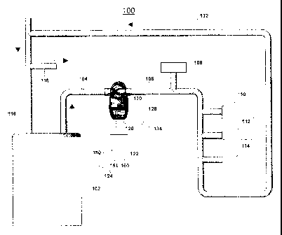
Fla IA is a diagram of a preferred smart pump installed in a hot water system
of
a newly constructed household.
FIG. 1B is a diagram showing a possible location of a preferred smart pump
installed in a retrofitted hot water system of a household.
FIG. 2 is a flow chart representing the operation of the smart pump in
automatic
mode and pulse mode.
CA 02790092 2012-08-15
WO 2011/103348 PCT/US2011/025322
6
DETAILED DESCRIPTION
Referring to FIG. 1A, there is shown the smart pump of the present invention
which comprises an electrically controlled water pump mechanism 130 coupled
via a
digital bus or signal interface 120 to a microcontroller 122 having an N-input
port 124
for receiving signals from one or more sensors 150, 151, 160 located
within the
pumping mechanism 130 or remotely from the water pumping mechanism 130 and one
of
said input ports, 150, is used to receive the state of a user controlled AUTO
switch (not
shown) for setting tb.e smart pump of the present invention in automatic mode
as
described below. N is an integer equal to 1 or greater. For ease of
explanation and to
provide some context to the operation of the smart pump of the present
invention, it is
shown as part of a closed water system of a household. The system has a hot
water tank
102 which receives cold water via pipe segment 118 and generates hot water
provided to
water pumping mechanism 130 via pipe segment 104. Water pump mechanism 130
pumps the hot water via pipe segment 106 to various hot water taps 108, 110,
112, and
114. The hot water return path is provided by pipe segment 132.
When set to the automatic mode with the AUTO switch (not shown), water pump
mechanism 130 pumps the hot water in accordance with the method of the present
invention as described herein. The various hot water taps are typical
locations (e.g.,
kitchen, bathroom sink, tub/shower, laundry) in a household where hot water is
used for
various purposes. The smart pump is powered with power cord 128 connected to
AC
outlet 134 for providing power. In other embodiments, the smart pump may be
powered
by batteries disposed within a cavity of the water pumping mechanism. Also,
microcontroller 122 along with signal interface 120, input port 124 and
associated
circuitry may be disposed within the same or other cavity of water pumping
mechanism
130. For ease of explanation, however, microcontroller 122, signal interface
120 and
input port 124 are shown as being external to the water pumping mechanism 130.
Microcontroller 122 may be any relatively inexpensive microprocessor or
microcomputer
integrated circuits that can be programmed with commands using many
commercially
available software packages. The programming language can be any well known
High
Level programming language.
CA 02790092 2012-08-15
WO 2011/103348 PCT/US2011/025322
7
The smart pump of the present invention can further comprise at least one
sensor
that detects the opening of a hot water tap, by changes in the flow of water
in the hot
water line, or by changes in the temperature of the water or pipe during a
period when the
pump is not in operation. To prevent accidental operation of the smart water
pump, the
microcontroller optionally can be programmed to require that the flow of water
continue
for a defined minimum period of time, before it is logged. The length of such
period
depends on the particular sensor being used and/or on the requirements of the
closed
water system.
The sensor can be located within a cavity of the water pump mechanism 130,
especially at the inlet to or outlet from the pump. Optionally, a sensor can
be remotely
located from the water pump mechanism 130, e.g., in FIG. 1B, hereto, the
sensor is
located at the desired location 106, and the pump located elsewhere, e.g., in
pipe 132 at
location 126, in-line with pipe 132, downstream from the taps, as shown in
FIG. 1B, in
similar fashion as it is installed in line with pipes 104 and 106, as shown in
FIG. 1A. This
often is the case when the system of this invention is installed after
construction of the
building, because it may not be convenient or efficient to install the pump
upstream from
the taps. A sensor at location 106, in the system of FIG. 1B, is remotely
located from the
pump 130, but is within the supply flow pipe segment 104/106, for detecting
the flow of
hot water resulting from hot water usage at any of the taps 108-114. When the
pump is
part of the original system included with the original construction of the
building, the
sensor is preferably located within the pump, at location 106, upstream of the
taps. Either
a remote sensor or a sensor disposed within the water pump mechanism (but not
both) can
be used.
As a further alternative, a sensor can be disposed at one or more of the taps
(110,
112, 114), to give a direct indication of flow through that tap.
It will be readily understood by one skilled in the art to which this
invention
belongs that water pump mechanism 130 can be any type of electrically
controllable or
electronically controllable mechanism designed to operate when triggered by
one or more
electronic or electrical signals. As shown here, the control signals for
operating the water
CA 02790092 2012-08-15
WO 2011/103348 PCT/US2011/025322
8
pump mechanism 130 are transmitted from the microcontroller 122 over
electrical control
motor interface 120. If desired, a wireless connection can also be provided.
The water pump mechanism 130 may require electric signals of a certain voltage
and current for proper operation. The control signals are transferred via the
control motor
interface 120 to operate, e.g., an on/off switch for the water pump
mechanism130; such
control signals can be transformed or converted to electrical signals of the
proper voltage
and/or current sufficient to operate the pumping mechanism 130. The particular
location
of the sensor(s) may sometimes reflect the time of installation of the smart
pump of the
present invention. Generally, smart pumps installed during construction of a
structure
(private house or commercial structure) are located intermediate the hot water
source (in
FIG 1A, a hot water tank 102 and the hot water taps, e.g., tap 108) and have
sensor(s)
located within or immediately adjacent the water pump mechanism 130; and a
smart
pump installed after construction can be located at another more accessible
part of the hot
water system, for example in the "Hot Water Return" line, as shown in FIG. 1B;
and in
that case the sensor is located remotely from the water pump mechanism 130,
such as,
preferably, at location 126 within the supply flow pipe line 104, downstream
from the hot
water tank.
When a sensor detects hot water flow or a sufficient temperature change (e.g.,
a
temperature rise) it sends a signal via a wire (or wirelessly) to the
microcontroller 122.
Additional circuitry (not shown, but conventionally available) is typically
needed to
convert the sensor signal to a proper format for reception by the
microcontroller 122.
Upon reception of the sensor signal, it is logged by the microcontroller 122,
which
controls the water pumping mechanism 130 and causes it to perform the steps of
the
method of the present invention.
Referring now to FIG. 2 there is shown a flow chart of the method of the
present
invention. Initially, power is provided to the smart pump and microcontroller
of the
present invention in step 202. In step 204, microcontroller 122 reads the
status of its
input port corresponding to the AUTO switch to determine whether a user of the
smart
pump has switched the smart pump to automatic operation. If automatic
operation is not
selected, the method of the present invention moves to step 230 and enters
the, e.g.,
CA 02790092 2012-08-15
WO 2011/103348 PCT/US2011/025322
9
PULSE mode wherein the smart pump continuously pumps water (regardless of the
sensor output) for a period of, e.g., 75 seconds every 15 minutes, or it can
be in the Off
mode, where the pump is not operating. As FIG. 2 shows, the smart pump of the
present
invention will remain in an operating mode, e.g., the PULSE mode of operation,
or Off,
until the AUTO switch is set to the automatic mode.
The method of the present invention moves to step 206 when microcontroller 122
has detected that AUTOMATIC operation has been selected. In step 206,
microcontroller
122 initializes a counter (i.e., a timer) that is to indicate the logging
period during which
various usages of hot water are detected, the length of time of each of said
usages, the
beginning and end of each of said usages. Documenting the time at which the
initial daily
hot water usage is detected, the length of each said usages and the beginning
and end of
each said usage, for each day, constitute logging a water usage. These various
usages are
logged within a certain time period and thus this period (typically 7 days) is
referred to as
the data logging period. Also, in step 206 another timer can be provided
(called the no
usage counter) which can be set to measure any period of no hot water usage
that exceeds
a certain threshold. For example, the threshold may be set to 36 hours. If no
hot water
usage is detected for 36 consecutive hours, the method of the present
invention will cause
the smart pump to enter into an IDLE or Off, mode of operation during which
the smart
pump does not pump any water until it detects hot water usage or detects a
signal to
restart. Thus, for example, after step 206, the method of the present
invention moves to
step 208 wherein microcontroller 122 monitors the sensor(s). If hot water
usage is not
detected, the no usage timer continues to measure the time of no usage and
when that
time exceeds a predefined period (36 hours, in our example) the smart pump
enters the
IDLE mode but the microcontroller continues to monitor the sensor(s). This is
reflected
by steps 208 to 210 to 226 to 224 and then back to step 208. The method of the
present
invention will remain in this IDLE loop defined by the aforementioned steps
until it
detects hot water usage or is signaled to restart. Note that during the IDLE
mode of
operation, the timer measuring the data logging period is also running. This
will allow
the pump to remain idle if there are days during the data logging period
(e.g., 7-day
period) when there is no hot water flow. Examples of no hot water usage
include time
CA 02790092 2012-08-15
WO 2011/103348 PCT/US2011/025322
periods when no one is occupying a residence due to vacation or occupants are
away for a
weekend for example.
The method of the present invention then moves to step 212 where detection of
hot water usage by a sensor has occurred and the resulting sensor signal is
read by
microcontroller 122. In step 212 the method of the present invention resets
the no usage
counter to zero time. Effectively, each time hot water usage is detected, the
no usage
counter is reset to zero. In step 214, start and end usage cycles (e.g., the
daily start times
and end times of hot water usage) of the detected water usage are detected,
for each day,
but a pre-run period of X minutes and a post-run period of Y minutes is
recorded or
logged for the start usage cycles and end usage cycles respectively. For
example, if on a
Tuesday, hot water usage is detected at 8:10 am at a fixture, then the
following Tuesday,
hot water will be supplied to that fixture starting at 7:10 am and ending at
9:10 am; here
X, the pre-run period is 60 minutes and Y, the post run period is also 60
minutes.
In another example, if a shower was used on a Friday starting at 6:00 am and
ending at 6:15 am, then the following Friday, hot water will be pumped to that
shower
starting at 5:00 am until 7:15 am where once again X and Y are 60 minutes. It
will be
readily obvious that the length of the X and Y periods is arbitrary and
different X and Y
times can be programmed. Also in the circumstance where there are different
sensors at
different taps or fixtures throughout the house or structure, the X and Y
times can be
programmed for a sensor located at each such tap or fixture. Also, the X and Y
times
need not necessarily be equal to each other. X and Y are variables
representing time
periods in minutes, hours or seconds or any combination thereof.
Throughout the data logging period, the method of the present invention
determines e.g., daily start cycles and end cycles as follows. The start of a
usage cycle is
determined by a sudden increase in the flow of water through the hot water
line, as occurs
when a tap is opened. Alternatively, the start of a usage cycle is determined
by a time
rate of change of water temperature of K degrees per L minutes after the pump
has been
off for M minutes or when the pump has been off for P minutes and the water
temperature
remains "hot." A "hot" water temperature is defined by a particular
temperature deemed
to be "hot" by the sensor(s) communicating with the microcontroller 122. That
is, the
CA 02790092 2012-08-15
WO 2011/103348 PCT/US2011/025322
11
sensor(s) can be set at a particular threshold temperature which if surpassed
by the
flowing water will cause the sensor(s) to indicate detection of "hot" water.
An end usage
cycle is defined as a no usage period of Z hours of no usage; for example Z
can equal to
2.8 hours. The variables K, L, M, P and Z represent real numbers greater than
zero.
A start usage cycle can represent the start time of a recirculation period. An
end
usage cycle can represent the end time of a recirculation period. That is, a
recirculation
period is defined by the period encompassed by a stored start usage cycle time
and a
stored end usage cycle time. A recirculation period may, therefore, comprise
one or more
start/end usage cycles. In steps 216 and 218, the start and end of the
recirculation periods
are thus determined from data gathered by the smart pump from the prior data
logging
period. At the end of the first logging period, the pump will operate during a
second
logging period in accordance with the data logged and accumulated during the
first
logging period. During the second and subsequent logging periods, while the
pump is
operating in accordance with the usage cycles defined from the previous data
logging
period, the sensors and microcontroller continue to operate in accordance with
the method
of the present invention and continue to measure, log and record the times of
hot water
usage and uses the new data to determine the times of operation of the pump
for the
succeeding data logging period; the recirculation periods are thus continually
updated.
The method of the present invention continues to log data for the duration of
the logging
period (e.g., 7 days). Once the data logging period expires at step 228, the
hot water
usage data pattern that has been logged by the controller is used to update
the operation of
the smart pump in step 222. In step 220, the pump is operated in accordance
with the
updated hot water usage data pattern for at least another data logging period
and the
method of the present invention continues to monitor and log (or record) new
data usage
times while the smart pump is operated as per the last updated data pattern.
In one embodiment of the present invention, the data measured determines the
earliest and latest times that hot water is used during any day of the logging
period, and
sets those times as the beginning and end of the pump operation during every
day of the
succeeding logging period. However, another embodiment can be used to log the
usage
times for each day of the week, and change the usage times accordingly. For
example,
CA 02790092 2012-08-15
WO 2011/103348
PCT/US2011/025322
12
during Monday to Friday of the week, the usage times start and end earlier
each day. On
the weekends, the usage times can start and end later each day.
The smart pump can be configured with a built-in power source and during a
power outage, the smart pump may not be able to pump water, but when power is
restored, the smart pump can return to its operating mode status immediately
prior to the
power outage. Another embodiment allows the smart pump to start a new data
logging
period upon restoration of power, the previous data having been lost when
power is lost.
Similarly, the microcontroller may have an initial setting pre-programmed in
its system
that will operate the pump during the initial start-up logging period, based
upon the
common usage of the general population, or it may be programmed when purchased
to
meet the requirements of the individual purchaser.
The device and method of the present invention have been described in terms of
various embodiments as described herein. It will be readily understood that
the
embodiments disclosed herein do not at all limit the scope of the present
invention. One
of ordinary skill in the art to which this invention belongs can, after
reading the
disclosure, implement the device and method of the present invention using
other
embodiments that are different from those disclosed herein but which are well
within the
scope of the invention as claimed below.