Note: Descriptions are shown in the official language in which they were submitted.
CA 02790478 2012-08-20
WO 2011/106077 PCT/US2011/000287
1
CATHETER ADAPTER
Field of the Invention
[001] The present invention relates to a medical device for coupling a
catheter to a fluid
delivery or storage device, and more particularly to an adapter for connecting
a catheter
to a fluid delivery or storage device that has its latching mechanisms
remotely located from
the exterior surfaces of the adapter to prevent accidental uncoupling of the
catheter.
Background of the Invention
[002] Catheter connector devices for coupling a catheter to a fluid delivery
or storage
device such as a syringe or a medicament fluid line is known. Such devices may
be used
for medical procedures including an epidural injection procedure whereby a
catheter is
inserted into a patient's epidural space so that medicament may be injected to
the patient
to locally anesthesize the patient for example during child birth. Before an
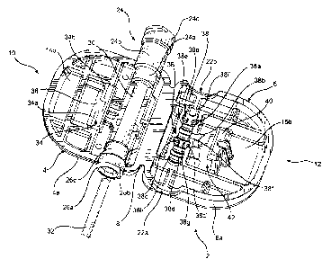
epidural
catheter can be inserted into the epidural space of the patient, an epidural
needle is first
inserted into the epidural space. Thereafter an epidural catheter is guided by
the needle
into the epidural space of the patient and the epidural needle is removed. A
catheter
connector device then connects the free end of the catheter to a syringe, a
fluid line or
other fluid store means that has the medicament. The prior art medical
catheter connector
devices would clamp the catheter and provide an end whereby the luer of the
syringe, fluid
line or other fluid store means may be connected so that a fluid path is
established
between the catheter and the syringe, fluid line or other fluid store means.
Some prior art
catheter connectors are disclosed in U.S. Patent Nos. 5,078,703, 4,006,744,
6,350,260,
7,635,355, and U.S. publication Nos. 2006/0271000, 2008/0183154.
[003] Most, if not all of the noted patents and publications disclose devices
having locking
mechanisms that are exposed, so that there may be accidental uncoupling of the
catheter.
The others of those disclosed devices require the relative twisting and
turning of portions
CA 02790478 2012-08-20
WO 2011/106077 PCT/US2011/000287
2
of the devices to align the catheter with the fluid store means, if the fluid
store means
happens to be a fluid line.
[004] The instant invention catheter adapter overcomes the disadvantages of
the prior art
catheter connectors.
Summary of the Present Invention
[005] The medical adapter of the instant invention is a one piece clam shell
shaped device
made of medical plastics such as polypropylene that includes two shells that
are integrally
connected by a common living hinge. The shells have counter matching
peripheries so
that when folded along the living hinge with their respective inner surfaces
facing each
other or in opposed relationship to each other, the peripheries of the shells
matchingly
abut. The shells are formed such that one of the shells is thinner than the
other. The
thinner shell has molded thereat a luer end at one end and an aperture end for
accepting
a catheter at its other end along a longitudinal axis that runs parallel and
adjacent to the
living hinge. An elastomeric flexible tubing or tube connects the luer end to
the aperture
end at the inner surface of the thinner shell so that a through path is
established between
the luer end and the aperture end. As the flexible tube connected luer and
aperture ends
are aligned adjacent to the living hinge, they are positioned offset from the
center of the
shell.
[006] At the approximate center of the thinner shell that has the luer and
aperture ends,
there is formed at the inner surface a latch mechanism that comprises a catch.
[007] At the other shell, which is the thicker of the two shells, of the
medical device of the
instant invention there is formed at approximately the center thereof at its
inner surface
another latch mechanism in the form of a finger that would snappingly grasp
the catch at
the other shell, when the two shells are movingly folded along the living
hinge towards each
other. When the shells are closed onto each other with their respective
peripheries
matchingly abut, the two shells are firmly engaged to each other due to the
finger at the
CA 02790478 2012-08-20
WO 2011/106077 PCT/US2011/000287
3
thicker shell lockingly coupled to the catch at the thinner shell. When thus
coupled, a
retainer surface structure at the inner surface of the thicker shell presses
against the
flexible tubing at the inner surface of the thinner shell to fixedly hold or
retain the catheter
that has been inserted through the aperture end into the flexible tubing.
[008] A notch or cavity to enable the decoupling of the shells is provided
from the outer
surface to the interior of the shell that has the latch finger. A pointed
object such as a
conventional male luer slip end of a syringe can be inserted into the notch to
push against
a boss at the back of the finger to disengage the finger from the catch, to
thereby decouple
the two shells and remove the pressure applied to the flexible tubing by the
retainer
structure. The catheter inserted to and extending along the flexible tubing
could then be
withdrawn from the device.
[009] Another feature of the instant invention device is that the formation of
the flexible
tubing is by injection molding an elastomeric material through a bore at the
outer surface
of the thinner shell so that the injected elastomeric material would congeal
to form the
flexible tubing that connects the luer fitting end to the aperture end. During
the injection
molding process, a soft elastomeric pad that enhances the ease with which a
user can
grasp the adapter is formed at the outer surface of the shell.
[0010] The present invention therefore relates to a one piece catheter
connector device
that comprises a first member or one shell and a second member or an other
shell each
having an inner surface and an outer surface. The one and other shells are
integrally
connected at a common living hinge and have respective matching peripheries to
form a
clam shell shaped member. The one shell has formed thereat a luer end and an
aperture
end connected by a flexible tubing at its inner surface so that a through
passage is
established between the luer end and the aperture end. The aperture end is
adapted to
accept a catheter input to said flexible tubing. The one shell has a first
latch mechanism
at its approximate center and the other shell has a second latch mechanism at
its
approximate center that lockingly engage to couple the one and other shells to
each other
CA 02790478 2012-08-20
WO 2011/106077 PCT/US2011/000287
4
when the one and other shells are folded along the common living hinge to move
the
respective inner surfaces of the one and other shells to face each other. The
other shell
includes a retainer structure at its inner surface that presses against the
flexible tubing to
fixedly hold or retain the catheter in the flexible tubing when the one and
other shells are
coupled to each other.
[0011] The instant invention also relates to an adapter for coupling a
catheter to a fluid
store or a fluid line that comprises a one piece clam shell shaped member
having one shell
and other shell integrally attached to and foldable toward each other by a
living hinge. The
one shell and other shell each have an inner surface and an outer surface. The
one shell
has formed thereat a luer end and an aperture end connected by a flexible
tubing at its
inner surface so that a through passage is established between the luer end
and the
aperture end. The aperture end is adapted to accept a catheter input to said
flexible
tubing. A first latch mechanism at approximately the center of the one shell
lockingly
engages a second latch mechanism at approximately the center of the other
shell when
the one and other shells are folded along the living hinge to close upon each
other. A
retainer structure at the inner surface of the other shell presses against the
flexible tubing
to fixedly hold or retain the catheter in the flexible tubing when the first
and second latch
mechanisms are engaged to each other.
[0012] The instant invention is further related to an apparatus that comprises
a catheter,
a fluid store means; and an adapter that includes a one piece clam shell
shaped member
having one shell and other shell integrally attached to and foldable toward
each other by
a living hinge. The one shell and the other shell each have an inner surface
and an outer
surface. The one shell has formed thereat a luer end and an aperture end
connected by
a flexible tubing at its inner surface so that a through passage is
established between the
luer end and the aperture end. The aperture end is adapted to accept the
catheter into the
flexible tubing and the luer end is adapted to mate with a counterpart luer at
the fluid store
means. A first latch mechanism at the one shell lockingly engages a second
latch
mechanism at the other shell when the one and other shells are folded along
the living
CA 2790978 2017-05-10
81585067
hinge to close upon each other. A retainer structure at the inner surface of
the other
shell presses against the flexible tubing to fixedly hold or retain the
catheter when the
first and second latch mechanisms are engaged to each other, whereby a fluid
path
between the catheter and the fluid store means is established by the adapter.
5 [0012a] In some embodiments, there is provided a catheter device,
comprising one
and other shells each having an inner surface and an outer surface, said one
and
other shells integrally connected at a common hinge and having respective
matching
peripheries to form a clam shell shaped member, said one shell having formed
thereat a luer end and an aperture end communicatively connected by a flexible
tubing at said one shell's inner surface so that a through passage is
established
between said luer end and said aperture end, said aperture end adapted to
accept a
catheter input to said flexible tubing, said one shell and said other shell
each having a
center at their respective center surfaces, said one shell having one latch
mechanism
at approximately the center of said one shell's inner surface, said other
shell having
other latch mechanism at approximately the center of said other shell's inner
surface,
said one and other latch mechanisms lockingly engage to couple said one and
other
shells to each other when said one and other shells are folded along the
common
hinge to move the respective inner surfaces of said one and other shells to
face each
other with said one and other latch mechanisms both inside the closed clam
shell
shaped member, said other shell including an inner surface retainer structure
that
presses against said flexible tubing to fixedly hold the catheter when said
one and
other shells are coupled to each other.
[0012b] In some embodiments, there is provided an adapter for coupling a
catheter to
a fluid store or a fluid line, comprising: a one piece clam shell shaped
member having
one shell and other shell integrally attached to and foldable toward each
other by a
living hinge, said one shell and said other shell each have an inner surface
and an
outer surface, said one shell having formed thereat a luer end and an aperture
end
connected by a flexible tubing at said one shell's inner surface so that a
through
passage is established between said luer end and said aperture end, said
aperture
11
CA 2790978 2017-05-10
81585067
5a
end adapted to accept the catheter input to said flexible tubing, said one
shell and
said other shell each having a center at their respective center surfaces, one
latch
mechanism at approximately the center of the inner surface of said one shell
lockingly engaging other latch mechanism at approximately the center of the
inner
surface of said other shell when said one and other shells are folded along
the living
hinge to close upon each other so that said one and other latch mechanism are
located inside the closed clam shell shaped member, a retainer structure at
the inner
surface of said other shell pressing against said flexible tubing to fixedly
hold the
catheter when said one and other latch mechanisms are engaged to each other.
[0012c] In some embodiments, there is provided apparatus comprising: a
catheter; a
fluid store means; an adapter including a one piece clam shell shaped member
having one shell and other shell integrally attached to and foldable toward
each other
by a living hinge, said one shell and said other shell each have an inner
surface and
an outer surface, said one shell having formed thereat a luer end and an
aperture
end connected by a flexible tubing at said one shell's inner surface so that a
through
passage is established between said luer end and said aperture end, said
aperture
end for accepting the catheter into said flexible tubing and said luer end for
mating
with a counterpart luer at said fluid store means, said one shell and said
other shell
each having a center at their respective center surfaces, one latch mechanism
at
approximately the center of the inner surface of said one shell lockingly
engaging
other latch mechanism at approximately the center of the inner surface of said
other
shell when said one and other shells are folded along the living hinge to
close upon
each other so that said one and other latch mechanism are located inside the
closed
clam shell shaped member, a retainer structure at the inner surface of said
other shell
pressing against said flexible tubing to fixedly hold the catheter when said
one and
other latch mechanisms are engaged to each other; whereby a fluid path between
said catheter and said fluid store means is established by said adapter.
I
CA 2790978 2017-05-10
81585067
5b
Brief Description of the Figures
[0013] The present invention will become apparent and the invention itself
will be best
understood by reference to the following description of the present invention
taken
injunction with the accompanying drawings, wherein:
[0014] Fig. 1 is a perspective view of the catheter adapter coupling device of
the
instant invention showing both shells of the device along the same plane;
[0015] Fig. 2 shows the device of Fig. 1 with the inner surfaces of both
shells of the
device exposed along the same plane;
[0016] Fig. 3 shows the device of the instant invention with both shells of
the device
closed upon each other to form a closed and/or coupled device;
[0017] Fig. 4 is a plan view of the outer surface of the one shell of the
device of the
instant invention having an elastomeric pad and an opening exposing the catch
latch
mechanism of the device;
[0018] Fig. 5 is a plan view of the outer surface of the other shell of the
device of the
instant invention showing a notch or cavity that exposes the boss of the
finger latch
mechanism located at the interior of the device;
[0019] Fig. 6 is a perspective view of the outer surfaces of the two shells of
the
instant invention medical device before the injection molding process of
forming the
flexible tubing in the device;
CA 02790478 2012-08-20
WO 2011/106077 PCT/US2011/000287
6
[0020] Fig. 7 is a perspective view of the inner surfaces of the two shells of
the instant
invention medical device before the injection molding process of forming the
flexible tubing
in the device
[0021] Fig. 8 shows in perspective a locked device of the instant invention
with its luer end
protected by a protective cover cap;
[0022] Fig. 9 is a perspective view of the outer surfaces of both shells of
the device lying
a coplanar relationship, with the luer end threadedly mated to a protective
cover cap; and
[0023] Fig. 10 corresponds to Fig. 2 but with the luer end threadedly mated to
a protective
cover cap.
Detailed Description of the Invention
[0024] With reference to Figs. 1-5, the medical catheter adapter 2 of the
instant invention
is a combination coupler and retainer device for connecting a catheter, for
example an
epidural catheter, to a fluid storage or fluid delivery device such as a
syringe and a fluid
line. In particular, device 2 is shown to be a single unitary device in the
shape of a clam
shell that has a first member or one shell 4 and a second member or other
shell 6 integrally
connected by a common living hinge 8 so that the shells are movable relative
towards each
other per the directions designated by directional arrows 10 and 12 to close
upon each
other in the closed position per shown in Fig. 3.
[0025] As shown in Figs. 1 and 2, shell 4 has an outer surface 14a and an
inner surface
14b, while shell 6 has an outer surface 16a and an inner surface 16b. For the
most part,
the peripheries 18 and 20 of shells 4 and 6, respectively, have counterpart
matching
configurations, so that when device 2 is in the closed position as shown in
Fig. 3,
peripheries 18 and 20 matchingly abut to form a closed container with no
external edges
from either of the shells showing beyond the common peripheries 18 and 20.
Accordingly,
CA 02790478 2012-08-20
WO 2011/106077 PCT/US2011/000287
7
the catheter adapter 2 of the instant invention, when in its closed and/or
coupled position,
is a compact device with a smooth boundary except for two connection ports as
will be
described, infra.
[0026] As shown in Fig. 2, the thickness of shell 4, designated 4a, is less
than the
thickness 6a of shell 6. In other words, shell 4 is a thinner shell than shell
6, which
periphery 20 includes semi-circumferential openings 22a and 22b having
respective
curvatures that allow shells 4 and 6 to close in light of the connection ports
formed at shell
4.
[0027] In particular, shell 4 has formed as a part thereof and extending
mostly from its
inner surface 14b two connection ports that may be referred to as a luer
fitting end (or luer
end) 24 and a catheter fitting aperture end (or an aperture end) 26. As device
2 comprises
a one piece body that is molded of medical plastics material such as
polypropylene, luer
end 24 and aperture end 26 are formed at the same time that device 2 is molded
so that
device 2, before the injection molding of an elastomeric material thereto, is
per shown in
Figs. 6 and 7.
[0028] Luer end 24 comprises a base 24a, a mid-section 24b and a fitting end
24c. The
outside diameter of mid-section 24b is configured to be slightly less than the
semi-
circumferential opening 22b at shell 6 so that opening 22b would form fit over
mid-section
24b when shells 4 and 6 are moved relative to each other per the direction
shown by
directional arrows 10 and 12 for closing and coupling the shells.
[0029] Aperture end 26, which may also be referred to as a catheter end, has
an aperture
opening 26a, a front end 26b and a base 26c. The outside diameter of front end
26b is
configured to be slightly less than the semi-circumferential opening 22a of
shell 6 so that
opening 22a would form fit over front end 26b when shells 4 and 6 are closed
per shown
in Fig. 3.
CA 02790478 2012-08-20
WO 2011/106077 PCT/US2011/000287
8
[0030] To establish a through path between luer end 24 and aperture end 26, an
elastomer is injection molded though a bore 28 (Figs. 6 and 7) from the outer
surface 14a
of shell 4 so that an elastomeric flexible tube or tubing 30 is formed at the
inner surface
14b of shell 4 for establishing a through passageway between luer end 24 and
aperture
end 26. Although not clearly shown, the elastomeric material extends partially
into base
portion 24a of luer end 24 at one end and is flush with aperture opening 26a
of aperture
end 26. Catheter 32, for example an epidural catheter, is insertable through
aperture
opening 26a into aperture end 26, and from there extends through flexible
tubing 30 into
base 24a of luer end 24. The insertion movement of the catheter is stopped by
an internal
shoulder (not shown) at the junction of base 24a and mid-section 24b of luer
end 24.
[0031] At inner surface 16b of shell 6 there is integrally formed a retainer
structure 38 that
has a length substantially the same as the length of the flexible tubing
between base 26c
of aperture end 26 and base 24a of luer fitting end 24. As illustrated in
Figs. 2 and 7,
retainer structure 38 may comprises a plurality of recesses 38a and 38a', 38b,
38c and
38c', and 38d, interspaced with a plurality of ribs 38e, 38f, 38g and 38h. The
respective
plurality of recesses and ribs together form a ribbed surface that slightly
curves inwardly
towards the inner surface 16b of shell 6 for contacting flexible tubing 30.
Also being part
of retainer structure 38 are two spatially opposed protrusions 38i and 38i'
positioned at the
end of the retainer structure that is proximate to semi-circumferential
opening 22b.
[0032] The ribbed surface of retainer structure 38 is configured to enable it
to form fittedly
press against flexible tubing 30 so that those portions of the elastomeric
material of flexible
tubing 30 that come into contact with the ribs are compressed by the ribs
while those
portions of the elastomeric material that end up being in opposed relationship
to the
recesses would remain substantially uncompressed so as to extend into the
recesses.
Thus, when shells 4 and 6 are moved to close upon each other, retainer
structure 38 -- and
in particular its ribbed contact surface formed by the protrusions 381 and
38i', the recesses
38a and 38a', 38b, 38c and 38c', and 38d, and the ribs 38e, 38f, 38g and 38h --
would
press against flexible tubing 30 such that there is a form fitting compressed
crimping of the
CA 02790478 2012-08-20
WO 2011/106077 PCT/US2011/000287
9
elastomeric material of the flexible tubing 30 by the respective recesses,
ribs and
protrusions of the retainer structure 38, so that catheter 32 positioned
lengthwise inside
flexible tubing 30 is held fixedly therein in a fluid sealingly tight
relationship. Putting it
differently, with the portion of retainer structure 38 that makes contact with
flexible tubing
30 configured per shown in Figs. 2 and 7, once the shells 4 and 6 are
lockingly coupled to
each other, as will be described infra, retainer structure 38 acts to
establish a fluid tight
seal between catheter 32 and flexible tubing 30 as well as to fixedly retain
catheter 32 and
flexible tubing 30 relative to each other. Also, the recesses, ribs and
protrusions of retainer
structure 38 are configured to have dimensions that ensure that there is no
crimping of the
catheter when retainer structure 38 compresses flexible tubing 30, so as not
to impede the
flow of fluid through catheter 32.
[0033] Thus, when shells 4 and 6 are moved via living hinge 8 to close upon
and securely
coupled to each other, per shown in Fig. 3, retainer structure 38 will press
against flexible
tubing 30 to fixedly hold catheter 32 along flexible tubing 30 without
crimpingly distorting
the through passage of catheter 32, and at the same time provide a fluid tight
seal between
catheter 32 and flexible tubing 30 to prevent fluid leakage from flexible
tubing 30 and
therefore the adapter. Catheter 32 is not removable from device 2 until shells
4 and 6 are
uncoupled and disengaged from each other.
[0034] Further with respect to shell 4, formed integrally at the inner surface
14b thereof
is a latch mechanism in the shape of an interrupted catch 34 that includes
catch members
34a and 34b. An opening 36 connects inner surface 14b to outer surface 14a of
shell 4.
[0035] To couple shells 4 and 6 in a locking relationship, integrally
extending from inner
surface 16b of shell 6 is another latch mechanism in the form of a latch
finger 40
interrupted at its middle by a boss 40a (Figs. 1 and 5) so that finger 40 may
be considered
to be divided into gripping finger portions 40b and 40c (Figs. 5 and 6).
CA 02790478 2012-08-20
WO 2011/106077 PCT/US2011/000287
[0036] With latch mechanisms 34 and 40 in cooperation, when shells 4 and 6 are
folded
along living hinge 8 so that their respective inner surfaces 14b and 16b face
each other,
with latch finger 40 snap fitted to catch 34, the adapter device 2 of the
instant invention
becomes a closed clam shell shaped container, per shown in Fig. 3, with the
catheter 32
inserted along flexible tube 30 via aperture end 26 being fixedly held or
retained to flexible
tubing 30 by retainer structure 38 of shell 6. A fluid through path or
passageway is thereby
established between luer end 24 and catheter 32.
[0037] As shown in Figs. 3-5, as the latch mechanisms 34 and 40 are located in
the
interior of the closed clam shell shaped device, they are therefore remotely
located from
the respective outer surfaces 14a and 16a of shells 4 and 6 of adapter device
2.
Moreover, as each of latch mechanisms 34 and 40 is located at approximately
the center
of its corresponding shells 4 and 6, latch mechanisms 34 and 40 are also
located remotely
from the peripheries 4a and 6a of shells 4 and 6. As a result, once engaged in
a locking
relationship, the latch mechanisms 34 and 40 are not exposed to the
environment, and
therefore could not easily be tampered with, or be accidentally disengaged
and/or
uncoupled from each other.
[0038] So that shells 4 and 6 could be uncoupled from each other, a
disengagement or
decouple through hole or notch 42 is provided at outer surface 16a of shell 6
to enable a
direct view into exposed latch finger 40, which is in a locking relationship
with catch 34.
A pointed object such as the male slip end of a syringe may be inserted into
notch 42 to
press against boss 40a to force latch finger 40 away from catch 34
(specifically catch
members 34a and 34b), thereby uncoupling shells 4 and 6 from each other. Once
shells
4 and 6 are uncoupled or disengaged from each other, flexible tube 30 is no
longer
pressedly held by retainer structure 38. Accordingly, catheter 32 can be
removed from
flexible tubing 30.
[0039] To supply medicament to a patient who has a catheter such as catheter
32 inserted
in her, assuming that catheter 32 has been inserted into and extends along
flexible tubing
CA 02790478 2012-08-20
WO 2011/106077 PCT/US2011/000287
11
30 and shells 4 and 6 of device 2 are lockingly coupled so that catheter 32 is
fixedly
retained in device 2, a fluid store such as a syringe 46 with a luer end 46a
may be
threadedly mated to luer 24c of luer end 24 so that the medicament in syringe
46 may be
conveyed to catheter 32 and from there delivered to the patient. For the
instant invention,
luer end 24 may be a conventional luer that is adapted to mate with a
conventional counter
luer of a conventional syringe, such as 46a shown in Fig. 3. For syringes or
fluid lines that
are specially designed to have a particular configuration or dimension, luer
end 24 could
be similarly configured to mate with those specially designed fluid delivery
and storage
devices.
[0040] As discussed above, flexible tubing 30 is formed by the injection
molding of an
elastomeric material through bore 28 of shell 4. As best shown in Fig. 6,
there is a shallow
pond or cavity 48 formed on outer surface 14a which, in addition to main bore
28 also has
smaller bores 50a and 50b. During the injection process, the elastomeric
material is
injected though bore 28 (with the appropriate die in opposed relationship to
inner surface
14b) to form the flexible tubing 30 between luer fitting end 24 and aperture
end 26 in the
mold space 50 at the inner surface 14b of shell 4, per shown in Fig. 7. An
appropriate
journal or pin-like rod extending between luer fitting end 24 and aperture end
26 effects the
through passageway for flexible tubing 30 during the injection molding
process.
[0041] In addition to flexible tubing 30, during the injection molding
process, the
elastomeric material also forms a flexible elastomeric pad 54 at shallow pond
48 flush with
the outer surface 14b of shell 4. The thus formed elastomeric pad 54, anchored
to bores
50a and 50b, in addition to possibly having some indicia for example the name
of the
assignee embossed thereon, provides the user with a touch responsive
elastomeric pad
for better grasping device 2. Thus, the injection molding of an elastomeric
material to shell
4 not only forms the flexible tubing 30 at inner surface 14b of shell 4, it
also forms a soft
elastomeric finger pad 54 at outer surface 14a of shell 4.
CA 02790478 2012-08-20
WO 2011/106077 PCT/US2011/000287
12
[0042] To provide sterility for the luer end 24, a protective cover cap 52 may
be threadedly
mated to luer end 24 of the device, per shown in Figs. 8-10.
[0043] Although the adapter device of the instant invention is disclosed for
use with an
epidural catheter, it should be appreciated that the adapter device as
disclosed could also
be used for other types of catheters by merely changing the diameter of the
aperture end,
i.e., the catheter connection port. So, too, although the luer end described
is a
conventional luer that is adapted to be used with a conventional counterpart
luer, the
dimensions of the luer end may be varied to mate with fittings of special
configurations and
dimensions to establish a fluid path between the fluid delivery, transfer or
storage device
and the catheter. Thus, inasmuch as the present invention is subject to many
variations,
modifications and changes in detail, it is intended that the matter described
throughout this
specification and shown in the accompanying drawings be interpreted as
illustrative only
and not in a limiting sense. Accordingly, it is intended that the invention be
limited only by
the spirit and scope of the hereto appended claims.