Note: Descriptions are shown in the official language in which they were submitted.
=
FLUID CHROMATOGRAPHY INJECTORS AND INJECTOR INSERTS
[0001]
[0002]
[0003]
[0004]
[0005] TECHNOLOGICAL FIELD
[0006] Certain embodiments described herein are directed to fluid injectors
and fluid injector
inserts configured for use with fluid chromatography devices such as, for
example, a gas
chromatography system.
[0007] BACKGROUND
[0008] Most chromatography systems include an injector assembly that permits
introduction
of a sample into the system. The materials commonly used in the injector
assemblies can
react with the sample and reduce the accuracy of the measurements.
[0009] SUMMARY
[0010] In one aspect, a fluid injector insert comprising an inlet and an
outlet, in which the
insert is constructed and arranged to couple to an injector assembly to
fluidically couple the
inlet of the insert to a fluid flow path of the injector assembly, in which
the inlet of the insert
comprises a substantially inert metal material is provided.
[0011] In certain examples, the substantially inert metal material is present
in a major
amount. In other examples, the substantially inert metal material comprises
titanium,
aluminum, yttrium or combinations thereof. In additional examples, the
substantially inert
metal material comprises titanium oxide, aluminum oxide, yttrium oxide or
combinations
thereof. In further examples, the substantially inert metal material comprises
nickel. In some
examples, the substantially inert metal material can be a HasteHoy alloy. In
certain
1
CA 2790810 2017-07-11
CA 02790810 2012-08-22
WO 2011/106642 PCT/US2011/026241
examples, the substantially inert metal material comprises chromium. In other
examples, the
substantially inert metal material can be an Inconel alloy. In additional
examples, the inlet
and the outlet each comprises a substantially inert metal material. In some
examples, the
substantially inert metal material of the inlet and the outlet are the same
material.
[0012] In another aspect, a fluid injector insert comprising an inlet and an
outlet, in which the
insert is constructed and arranged to couple to an injector assembly to
fluidically couple the
inlet to a fluid flow path of the injector assembly, in which the inlet of the
insert comprises a
non-catalytic metal material present in an effective amount to deter catalysis
by the inlet is
di sclosed.
[0013] In certain embodiments, the non-catalytic metal material is present in
a major amount.
In other embodiments, the non-catalytic metal material comprises titanium,
aluminum,
yttrium or combinations thereof. In further embodiments, the non-catalytic
metal material
comprises titanium oxide, aluminum oxide, yttrium oxide or combinations
thereof. In
additional embodiments, the non-catalytic metal material comprises nickel. In
some
embodiments, the non-catalytic metal material can be a HasteHoy alloy. In
some
embodiments, the non-catalytic metal material comprises chromium. In
additional
embodiments, the non-catalytic metal material can be an Inconel alloy. In
further
embodiments, the inlet and the outlet each comprises a non-catalytic metal
material. In some
embodiments, the non-catalytic metal material of the inlet and the outlet are
the same
material.
[0014] In an additional aspect, a fluid injector comprising an inlet and an
outlet, the fluid
injector further comprising a fluid flow path fluidically coupled to the
inlet, in which the inlet
and the outlet are configured to receive a chromatography column, and in which
the inlet
comprises a non-catalytic metal material present in an major amount to deter
catalysis by the
inlet is described.
[0015] In certain examples, the non-catalytic metal material comprises
titanium, aluminum,
yttrium or combinations thereof. In other examples, the non-catalytic metal
material
comprises titanium oxide, aluminum oxide, yttrium oxide or combinations
thereof. In
additional examples, the non-catalytic metal material comprises nickel. In
further examples,
the non-catalytic metal material can be a HasteHoy alloy. In some examples,
the non-
catalytic metal material comprises chromium. In other examples, the non-
catalytic metal
material can be an Inconel alloy. In additional examples, the inlet and the
outlet each
comprises a non-catalytic metal material present in an effective amount to
deter catalysis. In
2
CA 02790810 2012-08-22
WO 2011/106642 PCT/US2011/026241
some examples, the non-catalytic material of the inlet and the outlet are the
same material. In
other examples, the non-catalytic material of the inlet and the outlet are a
different material.
[0016] ln another aspect, a fluid injector comprising an inlet and an outlet,
the fluid injector
further comprising a fluid flow path fluidically coupled to the inlet, in
which the inlet and the
outlet are configured to receive a chromatography column, and in which the
inlet comprises a
major amount of a substantially inert metal material is provided.
[0017] In certain embodiments, the substantially inert metal material
comprises titanium,
aluminum, yttrium or combinations thereof. In some embodiments, the
substantially inert
metal material comprises titanium oxide, aluminum oxide, yttrium oxide or
combinations
thereof. In other embodiments, the substantially inert metal material
comprises nickel. In
additional embodiments, the substantially inert metal material can be a
HasteHoy alloy. In
other embodiments, the substantially inert metal material comprises chromium.
In further
embodiments, the substantially inert metal material can be an Inconel alloy.
In additional
embodiments, the inlet and the outlet each comprises a major amount of a
substantially inert
metal material. In other embodiments, the substantially inert metal material
of the inlet and
the outlet are the same material. In some embodiments, the substantially inert
metal material
of the inlet and the outlet are a different material.
[0018] ln an additional aspect, a fluid injector insert comprising an inlet
and an outlet, in
which the inlet comprises a non-catalytic, non-glass material present in an
effective amount
to deter catalysis by the inlet is disclosed.
[0019] In certain examples, the non-catalytic, non-glass material comprises
titanium,
aluminum, yttrium or combinations thereof. In some examples, the non-
catalytic, non-glass
material comprises titanium oxide, aluminum oxide, yttrium oxide or
combinations thereof.
In other examples, the non-catalytic, non-glass material comprises nickel. In
additional
examples, the non-catalytic, non-glass material can be a HasteHoy alloy. In
further
examples, the non-catalytic, non-glass material comprises chromium. In some
examples, the
non-catalytic, non-glass material can be an Inconel alloy. In certain
examples, the inlet and
the outlet each comprises a non-catalytic, non-glass material present in an
effective amount to
deter catalysis. In some examples, the non-catalytic, non-glass material of
the inlet and the
outlet are the same material. In other examples, the non-catalytic, non-glass
material of the
inlet and the outlet are a different material.
[0020] ln another aspect, a fluid injector insert comprising an inlet and an
outlet, in which the
inlet comprises a substantially inert non-glass, non-stainless steel material
is described.
3
CA 02790810 2012-08-22
WO 2011/106642 PCT/US2011/026241
[0021] In certain embodiments, the substantially inert non-glass, non-
stainless steel material
comprises titanium, aluminum, yttrium or combinations thereof. In some
embodiments, the
substantially inert non-glass, non-stainless steel material comprises titanium
oxide, aluminum
oxide, yttrium oxide or combinations thereof. In additional embodiments, the
substantially
inert non-glass, non-stainless steel material comprises nickel. In some
embodiments, the
substantially inert non-glass, non-stainless steel material can be a HasteHoy
alloy. In other
embodiments, the substantially inert non-glass, non-stainless steel material
comprises
chromium. In additional embodiments, the substantially inert non-glass, non-
stainless steel
material can be an Inconel alloy. In further embodiments, the inlet and the
outlet each
comprises a substantially inert non-glass, non-stainless steel material
present in an effective
amount to deter catalysis. In some embodiments, the substantially inert non-
glass, non-
stainless steel material of the inlet and the outlet are the same material. In
additional
embodiments, the substantially inert non-glass, non-stainless steel material
of the inlet and
the outlet are a different material.
[0022] In an additional aspect, a fluid injector insert comprising an inlet
and an outlet, each
of the inlet and the outlet comprising an internal channel coupled to each
other, in which the
insert is constructed and arranged to couple to an injector assembly to
fluidically couple the
inlet to a fluid flow path of the injector assembly, in which the inlet
comprises a substantially
inert metal oxide material is provided.
[0023] In certain examples, the substantially inert metal oxide material is
present in a major
amount. In other examples, the substantially inert metal oxide material
comprises titanium,
aluminum, yttrium or combinations thereof. In some examples, the substantially
inert metal
oxide material comprises titanium oxide, aluminum oxide, yttrium oxide or
combinations
thereof. In additional examples, the substantially inert metal oxide material
comprises nickel
or chromium.
[0024] In another aspect, a fluid injector insert comprising an inlet and an
outlet, each of the
inlet and the outlet comprising an internal channel coupled to each other, in
which the insert
is constructed and arranged to couple to an injector assembly to fluidically
couple the inlet to
a fluid flow path of the injector assembly, in which the inlet comprises a non-
catalytic metal
oxide material present in an effective amount to deter catalysis by the inlet
is disclosed.
[0025] In certain embodiments, the non-catalytic metal oxide material is
present in a major
amount. In other embodiments, the non-catalytic metal oxide material comprises
titanium,
aluminum, yttrium or combinations thereof. In additional embodiments, the non-
catalytic
metal oxide material comprises titanium oxide, aluminum oxide, yttrium oxide
or
4
CA 02790810 2012-08-22
WO 2011/106642 PCT/US2011/026241
combinations thereof. In further embodiments, the non-catalytic metal oxide
material
comprises nickel or chromium.
[0026] In an additional aspect, a fluid injector comprising an inlet and an
outlet, each of the
inlet and the outlet comprising an internal channel coupled to each other, the
fluid injector
further comprising a fluid flow path fluidically coupled to the inlet, in
which the inlet
comprises a non-catalytic metal oxide material present in an major amount to
deter catalysis
is described.
[0027] In certain examples, the non-catalytic metal oxide material is present
in a major
amount. In additional examples, the non-catalytic metal oxide material
comprises titanium,
aluminum, yttrium or combinations thereof. In some examples, the non-catalytic
metal oxide
material comprises titanium oxide, aluminum oxide, yttrium oxide or
combinations thereof.
In other examples, the non-catalytic metal oxide material comprises nickel or
chromium.
[0028] In another aspect, a fluid injector comprising an inlet and an outlet,
the fluid injector
further comprising a fluid flow path fluidically coupled to the inlet, in
which the inlet
comprises a substantially inert metal oxide material is provided.
[0029] In certain embodiments, the substantially inert metal oxide material is
present in a
major amount. In other embodiments, the substantially inert metal oxide
material comprises
titanium, aluminum, yttrium or combinations thereof. In further embodiments,
the
substantially inert metal oxide material comprises titanium oxide, aluminum
oxide, yttrium
oxide or combinations thereof. In additional embodiments, the substantially
inert metal oxide
material comprises nickel or chromium.
[0030] In an additional aspect, an injector assembly comprising an injector
housing
comprising a fluid flow path, and an injector insert mated to the injector
housing, the injector
insert comprising an inlet and an outlet, in which the fluid flow path of the
injector housing is
fluidically coupled to the inlet of the injector insert, in which the inlet
comprises a
substantially inert metal material is disclosed.
[0031] In certain examples, the substantially inert metal material is present
in a major
amount. In some examples, the substantially inert metal material comprises
titanium,
aluminum, yttrium or combinations thereof. In other examples, the
substantially inert metal
material comprises titanium oxide, aluminum oxide, yttrium oxide or
combinations thereof.
In additional examples, the substantially inert metal material comprises
nickel or chromium.
[0032] In another aspect, an injector assembly comprising an injector housing
comprising a
fluid flow path, and an injector insert mated to the injector housing, the
injector insert
comprising an inlet and an outlet, in which the fluid flow path of the
injector housing is
CA 02790810 2012-08-22
WO 2011/106642 PCT/US2011/026241
fluidically coupled to the inlet of the injector insert, in which the inlet
comprises a non-
catalytic metal material present in an effective amount to deter catalysis by
the inlet is
described.
[0033] In certain embodiments, the non-catalytic metal material is present in
a major amount.
In other embodiments, the non-catalytic metal material comprises titanium,
aluminum,
yttrium or combinations thereof. In some embodiments, the non-catalytic metal
material
comprises titanium oxide, aluminum oxide, yttrium oxide or combinations
thereof. In
additional embodiments, the non-catalytic metal material comprises nickel or
chromium.
[0034] In an additional aspect, an injector assembly comprising an injector
housing
comprising a fluid flow path, and an injector insert mated to the injector
housing, the injector
insert comprising an inlet and an outlet, in which the fluid flow path of the
injector housing is
fluidically coupled to the inlet of the injector insert, in which the inlet
comprises a
substantially inert metal oxide material is provided.
[0035] In certain examples, the substantially inert metal oxide material is
present in a major
amount. In additional examples, the substantially inert metal oxide material
comprises
titanium, aluminum, yttrium or combinations thereof. In further examples, the
substantially
inert metal oxide material comprises titanium oxide, aluminum oxide, yttrium
oxide or
combinations thereof. In some examples, the substantially inert metal oxide
material
comprises nickel or chromium.
[0036] In another aspect, an injector assembly comprising an injector housing
comprising a
fluid flow path, and an injector insert mated to the injector housing, the
injector insert
comprising an inlet and an outlet, in which the fluid flow path of the
injector housing is
fluidically coupled to the inlet of the injector insert, in which the inlet
comprises a non-
catalytic metal oxide material present in an major amount to deter catalysis
by the inlet is
disclosed.
[0037] In certain embodiments, the non-catalytic metal oxide material is
present in a major
amount. In other embodiments, the non-catalytic metal oxide material comprises
titanium,
aluminum, yttrium or combinations thereof. In additional embodiments, the non-
catalytic
metal oxide material comprises titanium oxide, aluminum oxide, yttrium oxide
or
combinations thereof. In further embodiments, the non-catalytic metal oxide
material
comprises nickel or chromium.
[0038] In an additional aspect, an injector assembly comprising an injector
housing
comprising a fluid flow path, and an injector insert mated to the injector
housing, the injector
insert comprising an inlet and an outlet, in which the fluid flow path of the
injector housing is
6
CA 02790810 2012-08-22
WO 2011/106642 PCT/US2011/026241
fluidically coupled to the inlet of the injector insert, in which the inlet
comprises a non-
catalytic, non-glass material present in an effective amount to deter
catalysis is described.
[0039] ln certain examples, the non-catalytic, non-glass material is present
in a major
amount. In other examples, the non-catalytic, non-glass material comprises
titanium,
aluminum, yttrium or combinations thereof. In some examples, the non-
catalytic, non-glass
material comprises titanium oxide, aluminum oxide, yttrium oxide or
combinations thereof.
In additional examples, the non-catalytic, non-glass material comprises nickel
or chromium.
[0040] In another aspect, an injector assembly comprising an injector housing
comprising a
fluid flow path, and an injector insert coupled to the injector housing, the
injector insert
comprising an inlet and an outlet, in which the fluid flow path of the
injector housing is
fluidically coupled to the inlet of the injector insert, in which the insert
comprises a
substantially inert non-glass, non-stainless steel material is provided.
[0041] In certain embodiments, the substantially inert non-glass, non-
stainless steel material
is present in a major amount. In other embodiments, the substantially inert
non-glass, non-
stainless steel material comprises titanium, aluminum, yttrium or combinations
thereof. In
further embodiments, the substantially inert non-glass, non-stainless steel
material comprises
titanium oxide, aluminum oxide, yttrium oxide or combinations thereof. In some
embodiments, the substantially inert non-glass, non-stainless steel material
comprises nickel
or chromium.
[0042] In an additional aspect, a kit comprising an injector insert
constructed and arranged to
couple to an injector assembly, the injector insert comprising an inlet and an
outlet, in which
the inlet comprises a substantially inert metal material is provided.
[0043] In certain examples, the kit can include the injector assembly. In
other examples, the
kit can include an additional injector insert constructed and arranged to
couple to the injector
assembly, the additional injector insert comprising an inlet and an outlet, in
which the inlet of
the additional injector comprises a substantially inert metal material. In
some examples, the
substantially inert metal material of the inlet of the additional injector
insert is different than
the substantially inert metal material of the inlet of the injector insert. In
other examples, the
kit can include a third injector insert constructed and arranged to couple to
the injector
assembly, the third injector insert comprising an inlet and an outlet, in
which the inlet of the
third injector insert comprises a substantially inert metal material.
[0044] ln another aspect, a kit comprising an injector insert constructed and
arranged to
couple to an injector assembly, the injector insert comprising an inlet and an
outlet, in which
7
CA 02790810 2012-08-22
WO 2011/106642 PCT/US2011/026241
the inlet comprises a non-catalytic metal material present in an effective
amount to deter
catalysis by the inlet is disclosed.
[0045] In certain embodiments, the kit can include the injector assembly. In
other
embodiments, the kit can include an additional injector insert constructed and
arranged to
couple to the injector assembly, the additional injector insert comprising an
inlet and an
outlet, in which the inlet of the additional injector insert comprises a non-
catalytic metal
material present in an effective amount to deter catalysis by the inlet. In
additional
embodiments, the non-catalytic metal material of the inlet of the additional
injector insert is
different than the non-catalytic metal material of the inlet of the injector
insert. In some
embodiments, the kit can include a third injector insert constructed and
arranged to couple to
the injector assembly, the third injector insert comprising an inlet and an
outlet, in which the
inlet of the third injector insert comprises a non-catalytic metal material
present in an
effective amount to deter catalysis by the inlet of the third injector insert.
[0046] In an additional aspect, a kit comprising an injector insert
constructed and arranged to
couple to an injector assembly, the injector insert comprising an inlet and an
outlet, in which
the inlet comprises a non-catalytic, non-glass material present in an
effective amount to deter
catalysis by the inlet is described.
[0047] In certain examples, the kit can include the injector assembly. In
other examples, the
kit can include an additional injector insert constructed and arranged to
couple to the injector
assembly, the additional injector insert comprising an inlet and an outlet, in
which the inlet of
the additional injector insert comprises a non-catalytic, non-glass material
present in an
effective amount to deter catalysis by the inlet of the additional injector
insert. In other
examples, the non-catalytic, non-glass material of the inlet of the additional
injector insert is
different than the non-catalytic, non-glass material of the inlet of the
injector insert. In some
examples, the kit can include a third injector insert constructed and arranged
to couple to the
injector assembly, the third injector insert comprising an inlet and an
outlet, in which the inlet
of the third injector insert comprises a non-catalytic, non-glass material
present in an
effective amount to deter catalysis by the inlet of the third injector insert.
[0048] In another aspect, a kit comprising an injector insert constructed and
arranged to
couple to an injector assembly, the injector insert comprising an inlet and an
outlet, in which
the inlet comprises a substantially inert non-glass, non-stainless steel
material is provided.
[0049] In certain embodiments, the kit can include the injector assembly. In
other
embodiments, the kit can include an additional injector insert constructed and
arranged to
couple to the injector assembly, the additional injector insert comprising an
inlet and an
8
CA 02790810 2012-08-22
WO 2011/106642 PCT/US2011/026241
outlet, in which the inlet of the additional injector insert comprises a
substantially inert non-
glass, non-stainless steel material. In some embodiments, the substantially
inert non-glass,
non-stainless steel material of the inlet of the additional injector insert is
different than the
substantially inert non-glass, non-stainless steel material of the inlet of
the injector insert. In
certain embodiments, the kit can include a third injector insert constructed
and arranged to
couple to the injector assembly, the third injector adapter comprising an
inlet and an outlet, in
which the inlet of the third injector insert comprises a substantially inert
non-glass, non-
stainless steel material.
[0050] In an additional aspect, a kit comprising an injector insert
constructed and arranged to
couple to an injector assembly, the injector insert comprising an inlet and an
outlet, in which
the inlet comprises a substantially inert metal oxide material is disclosed.
[0051] In certain examples, the kit can include the injector assembly. In
other examples, the
kit can include an additional injector insert constructed and arranged to
couple to the injector
assembly, the additional injector insert comprising an inlet and an outlet, in
which the inlet of
the additional injector insert comprises a substantially inert metal oxide
material. In further
examples, the substantially inert metal oxide material of the inlet of the
additional injector
insert is different than the substantially inert metal oxide material of the
inlet of the injector
insert. In some examples, the kit can include a third injector insert
constructed and arranged
to couple to the injector assembly, the third injector insert comprising an
inlet and an outlet,
in which the inlet of the third injector insert comprises a substantially
inert metal oxide
material.
[0052] In another aspect, a kit comprising an injector insert constructed and
ananged to
couple to an injector assembly, the injector insert comprising an inlet and an
outlet, in which
the inlet comprises a non-catalytic metal oxide material present in an
effective amount to
deter catalysis by the inlet is provided.
[0053] In certain embodiments, the kit can include the injector assembly. In
further
embodiments, the kit can include an additional injector insert constructed and
arranged to
couple to the injector assembly, the additional injector insert comprising an
inlet and an
outlet, in which the inlet of the additional injector insert comprises a non-
catalytic metal
oxide material present in an effective amount to deter catalysis by the inlet
of the additional
injector insert. In some embodiments, the non-catalytic metal oxide material
of the inlet of
the additional injector insert is different than the non-catalytic metal oxide
material of the
inlet of the injector insert. In other embodiments, the kit can include a
third injector insert
constructed and arranged to couple to the injector assembly, the third
injector insert
9
comprising an inlet and an outlet, in which the inlet of the third injector
insert comprises a non-
catalytic metal oxide material present in an effective amount to deter
catalysis by the inlet of
the third injector insert.
According to one aspect of the present invention there is provided a gas
chromatography
injector assembly comprising: an inlet configured to fluidically couple to a
carrier gas, an outlet
fluidically coupled to the inlet and configured to vent carrier gas from the
injector assembly; a
liner fluidically coupled to the inlet at a first end and configured to
fluidically couple to a
chromatography column at a second end to provide a fluid flow path between the
inlet and the
column; and an injector insert positioned at the second end of the liner and
comprising an
injector insert inlet coupled to a separate injector insert outlet to provide
a channel between the
coupled injector insert inlet and the injector insert outlet, wherein the
injector insert inlet is
constructed and arranged to fluidically couple to a fluid flow path from the
inlet so that a top
surface of the injector insert inlet will be exposed to sample in the fluid
flow path, wherein the
top surface of the injector insert inlet comprises an inert metal material
that is exposed to the
sample in the fluid flow path, and wherein the injector insert outlet and the
channel are
configured to receive a column to fluidically couple the received column to
the injector insert
inlet and to provide fluidic coupling between the inlet and the column to
permit sample to flow
from the inlet to the column.
According to a further aspect of the present invention there is provided a gas
chromatography injector assembly comprising: an inlet configured to
fluidically couple to a
carrier gas, an outlet fluidically coupled to the inlet and configured to vent
carrier gas from the
injector assembly; a liner fluidically coupled to the inlet at a first end and
configured to
fluidically couple to a chromatography column at a second end to provide a
fluid flow path
between the inlet and the column; and an injector insert comprising an
injector insert inlet
coupled to a separate injector insert outlet to provide a channel between the
injector insert inlet
and the injector insert outlet, wherein the injector insert inlet is
constructed and arranged to
fluidically couple to the fluid flow path so that a top surface of the
injector insert inlet will be
exposed to sample in the fluid flow path, wherein the top surface of the
injector insert inlet
comprises a non-catalytic metal material present in an effective amount to
deter catalysis by
the top surface of the injector insert inlet that is exposed to the sample in
the fluid flow path
under selected gas chromatographic conditions, and wherein the injector insert
outlet and the
channel are configured to receive a column to fluidically couple the received
column to the
injector insert inlet and to provide fluidic coupling between the inlet and
the column to permit
sample to flow from the inlet to the column.
CA 2790810 2017-07-11
According to another aspect of the present invention there is provided a
method of
facilitating gas chromatographic analysis of a sample, the method comprising
providing an
injector assembly as described herein.
[0054] Additional features, aspect, examples and embodiments are described in
more detail
below.
[0055] BRIEF DESCRIPTION OF THE FIGURES
[0056] Certain embodiments are described with reference to the figures in
which:
[0057] FIG. 1 is a cross-section of an injector assembly insert, in accordance
with certain
examples;
[0058] FIG. 2 is a cross-section of an injector insert, in accordance with
certain examples;
[0059] FIG. 3 is a cross-section of an injector insert in which the inlet
comprises external
threads to couple to the outlet, in accordance with certain examples;
[0060] FIG. 4 is a schematic of an injector insert, in accordance with certain
examples;
[0061] FIG. 5 is an exploded view of an inlet and an outlet of an injector
insert, in
accordance with certain examples;
[0062] FIG. 6 is a schematic of a gas chromatography system, in accordance
with certain
examples;
[0063] FIG. 7 is a photograph showing the injector insert used in certain
measurements, in
accordance with certain examples;
[0064] FIG. 8 is a graph showing recovery tests for a mixture of species using
a standard
stainless steel injector insert, a gold-plated injector insert and an insert
including a titanium
inlet, in accordance with certain examples;
[0065] FIG. 9 shows the results of a splitless TIC chromatography measurement
using a US-
EPA 8270 standard mixture, in accordance with certain examples;
[0066] FIG. 10 shows a the recovery results of injection of 0.5 ng of 2,4-
dinitrophenol using
splitless TIC chromatography and a stainless steel insert and an inlet
comprising a titanium
insert, in accordance with certain examples; and
[0067] FIG. 11 is a table showing test results for 2,4-dinitrophenol using a
stainless steel
insert, a gold-plated insert, a titanium insert and a polished titanium insert
where the ring
refers to a graphite seal, in accordance with certain examples.
[0068] It will be recognized by the person of ordinary skill in the art, given
the benefit of
this disclosure, that certain dimensions or features in the figures may have
been enlarged,
distorted or shown in an otherwise unconventional or non-proportional manner
to provide a
10a
CA 2790810 2017-07-11
CA 02790810 2012-08-22
WO 2011/106642 PCT/US2011/026241
more user friendly version of the figures. Where dimensions are specified in
the description
below, the dimensions are provided for illustrative purposes only.
[0069] DETAILED DESCRIPTION
[0070] Certain examples described herein are directed to injector inserts and
injectors that
include one or more materials that can render at least some portion of the
injector insert or
injector substantially inert or non-catalytic. The term "insert" is used
herein in certain
instances and is not intended to imply that the entire device or even any
portion of the device
need actually be inserted into another device. In some examples, a portion of
an insert can
couple to another device such as, for example, an injector assembly housing,
and some
portion of the insert may be inserted into the housing or the entire insert
can be adjacent to
but not actually inserted into the housing. The term "insert" is intended to
be interchangeable
with the term "adapter." One advantage of the inserts described herein is that
different inserts
can be selected and used with a single injector housing assembly. Depending on
the species
to be analyzed, the entire injector assembly need not be changed but instead a
desired insert
can be used to mitigate any unwanted effects that might result from using just
the injector
assembly by itself without any insert. For example, an injector insert
designed to couple to
an injector assembly can include a substantially inert material on a top
surface that is exposed
to a sample fluid flow in an injector assembly. By including the substantially
inert material
on surfaces that are exposed to sample, the sample that contacts or resides
near the surface
does not react with the surfaces to any substantial degree, and unwanted
reactions are not
catalyzed by the surface in any appreciable amounts. As described in more
detail below, the
particular type and amount of material on or in the surface can vary, and
different types of
materials may be desirably present to render the surface substantially inert.
[0071] In certain embodiments, the entire injector insert, if desired, can be
produced from the
substantially inert or non-catalytic materials. As described in more detail
below, substantially
inert materials are those materials that do not react with, catalyze or are
otherwise affected by
analytes in a sample stream to any substantial degree. Non-catalytic materials
are materials
that are not necessarily inert under all conditions, but they do not catalyze
any reactions to a
substantial degree under selected chromatographic conditions. For example, a
non-catalytic
material has suitable properties such that it does not catalyze any reaction
during the time a
sample is resident or exposed to the surface of the injector insert. There can
be overlap of
substantially inert materials and non-catalytic materials since substantially
inert materials also
do not catalyze reactions to any substantial degree no matter the residence
time of the sample
11
CA 02790810 2012-08-22
WO 2011/106642 PCT/US2011/026241
near the surface of the injector insert. Specific types and amounts of each of
the materials are
described in more detail below. To reduce overall cost, it may be desirable to
include the
substantially inert or non-catalytic materials only on surfaces or in
components that are
exposed to the sample, and other portions of the insert can be produced using
conventional
materials such as stainless steel.
[0072] In certain embodiments, illustrative types of materials that can be
substantially inert
and/or non-catalytic and are suitable for use in one or more components of the
injector inserts
(or entire injectors) include, but are not limited to, titanium, titanium
oxide, yttrium, yttrium
oxide, aluminum, aluminum oxide, nickel, nickel alloys, chromium, chromium
alloys, nickel
chromium alloys and the like. Desirable nickel alloys include, but are not
limited to, a
Hastelloy@ A alloy, a Hastelloy@ B alloy, a Hastelloy@ B2 alloy, a Hastelloy@
B3 alloy, a
Hastelloy@ B142T alloy, a Hastelloy@ Hybrid-BC1 alloy, a Hastelloy@ C alloy, a
Hastelloy@ C4 alloy, a Hastelloy@ C22 alloy, a Hastelloy@ C22HS alloy, a
Hastelloy@
C2000 alloy, a Hastelloy@ C263 alloy, a Hastelloy@ C276 alloy, a Hastelloy@ D
alloy, a
Hastelloy@ G alloy, a Hastelloy@ G2 alloy, a Hastelloy@ G3 alloy, a Hastelloy@
G30 alloy,
a Hastelloy@ G50 alloy, a Hastelloy@ H9M alloy, a Hastelloy@ N alloy, a
Hastelloy@ R235
alloy, a Hastelloy@ S alloy, a Hastelloy@ W alloy, a Hastelloy@ X alloy and
other
Hastelloy0 alloys commercially available from Haynes International, Inc.
(Kokomo, IN). In
some examples, the substantially inert material or the non-catalytic material
can be a nickel-
chromium alloy such as an Inconel@ 600 alloy, an Inconel@ 625 alloy, an
Inconel@ 718
alloy or other Inconel() alloys commercially available from Special Metals
Corporation (New
Hartford, NY). Combinations of these various materials can also be used. One
or more of
these materials can be present on a surface of the insert such that exposure
of the sample to
the surface does not result in any unwanted chemical reactions.
[0073] While certain embodiments below are described in reference to injector
inserts, the
components of the injector insert could be used instead in a fluid injector.
For example, a
fluid flow path in an entire fluid injector or fluid injector assembly can
include a substantially
inert or non-catalytic material to render the fluid flow paths of those
devices substantially
non-reactive with a sample introduced into them. Alternatively, the fluid
injector can include
an integrated inlet that includes one or more substantially inert materials or
non-catalytic
materials. It will be within the ability of the person of ordinary skill in
the art, given the
benefit of this disclosure, to use the materials described herein in both
fluid injector inserts
and fluid injectors.
12
CA 02790810 2012-08-22
WO 2011/106642 PCT/US2011/026241
[0074] In certain examples, the injector inserts described herein can be used
with split or
split-less injector assemblies, can be used with conventional chromatography
injectors,
capillary injectors or other types of injectors. In addition, the injector
insert can be used in
many different types of fluid chromatography including gas chromatography and
liquid
chromatography. For illustration purposes only, one injector assembly is shown
in FIG. 1.
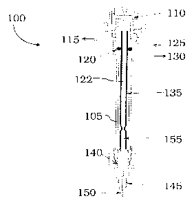
The injector 100 includes a housing 105, a septum 110, a septum purge 115, an
0-ring 120, a
carrier gas inlet 125, an outlet 130, a liner 135, an injector insert 140, and
a fitting 145. The
injector 100 can couple to a column 150 that includes a tip 155. The insert
140 can be any of
the insert described herein. In use of the injector 100, a sample is
introduced through the
septum 110 using a needle or other suitable device. A carrier gas entering
inlet 125 can
entrain the sample and carry some portion to the column 150. The column 150 is
typically in
a heated oven. The insert 140 is also typically heated. A top surface of the
insert 140 is
fluidically coupled to a fluid flow path 122 of the injector 100 such that
some portion of the
insert 140 is exposed to the sample in the injector 100.
[0075] In certain embodiments, exposure of the heated insert to certain
compounds can result
in unwanted side reactions. For example, labile compounds such as conjugated
phenols and
phosphorous pesticides, e.g., 2-4 dinitrophenol, methamidophos, etc., exhibit
losses during
introduction into a gas chromatography (GC) system. This loss is exacerbated
with the use of
volatile solvents such as dichloromethane. The problem can be severe when a
hot, split-less
injection technique is used for low level applications. A portion of the loss
in the injection
of labile compounds can be attributed to interaction and reactions with hot
stainless steel
surfaces within the injector port. Many industrial metals have catalytic
affects when hot.
One observable result of the losses during injection is a non¨linear response
across a
concentration range. This issue may result in dissatisfaction of the end
user if their
application includes trace level detection of labile compounds, and they
desire to use a
volatile solvent coupled with hot split-less injections in a capillary
injector assembly.
[0076] In certain embodiments, the inlet of injector inserts described herein
can include one
or more substantially inert metal materials. The term "inlet" is used herein
to refer to the top
surfaces of the injector insert and is typically the portion of the insert
that is exposed to the
sample. As described in more detail below, the injector insert can also
include an outlet that
is coupled to or integral with the inlet of the insert. The outlet is
typically coupled to another
component that couples to the oven of the system. In some examples, the inlet
may be
produced entirely from the substantially inert metal material or may include a
sufficient
amount of the metal material to render the inlet substantially inert. For
example, the inlet can
13
CA 02790810 2012-08-22
WO 2011/106642 PCT/US2011/026241
include a major amount, e.g., greater than 50% by weight, of the substantially
inert metal
material and can also include other inert materials. The substantially inert
material can be
coated to a desired thickness on the inlet or the inlet can be produced from
the substantially
inert material to minimize the chance any coating may flake off or leach off
and interfere
with the analysis. In certain embodiments, the substantially inert material or
the non-catalytic
material can be present in a non-coated form, e.g., no coating is present.
[0077] In certain examples, during operation of the chromatography system, the
substantially
inert metal material of the inlet may remain in its deposited form or may
oxidize to another
substantially inert metal material, e.g., a substantially inert metal oxide
material. For
example, the inlet of the insert can be produced using titanium and, during
operation the
system, the inlet can be heated to a desired temperature. Heating of the inlet
can produce
oxide formation in or on the inlet. For example, where titanium is used in the
inlet, the
titanium can be oxidized to titania (titanium oxide). Alternatively and if
desired, the titanium
inlet can be oxidized to titania (titanium oxide) prior to use. For example,
the inlet can be
sintered under non-oxidizing conditions to maintain the metal as deposited,
whereas in other
examples the inlet can be sintered under oxidizing conditions, e.g., in an
atmosphere
including oxygen, to promote oxide formation in or on the inlet.
[0078] In other examples, the inlet can include a non-catalytic material. In
contrast to a
substantially inert material, the non-catalytic material may be less inert and
may react with
certain species under certain conditions. The non-catalytic material desirably
does not
catalyze any reactions under the chromatographic conditions that are used.
Even though the
non-catalytic material may not be substantially inert under all conditions, it
will not catalyze
any reaction between analytes in the sample stream in the selected
chromatographic
conditions. The non-catalytic metal material is typically present in an
effective amount to
deter catalysis of any chemical reactions of species in the sample stream. In
some examples,
the non-catalytic metal material can be present in a major amount, e.g., 50%
or more by
weight, in the inlet of the injector insert. It may be desirable to use a non-
catalytic material
where a user knows that none of the species in the analyte stream will react
or be catalyzed.
The use of a non-catalytic material may also reduce costs by permitting the
use of cheaper
materials in the inlet of the insert.
[0079] In certain embodiments, a cross-section of an injector insert is shown
schematically in
FIG. 2. The injector insert 200, also referred to in certain instances herein
as an injector
adapter, includes an inlet 210 and an outlet 230. The insert 200 can also
include a channel
230 that runs from the top surface of the inlet 210 to a bottom surface of the
outlet 220. The
14
CA 02790810 2012-08-22
WO 2011/106642 PCT/US2011/026241
channel can be sized and arranged to receive a capillary column, for example.
At least some
portion of the inlet 210 can be fluidically coupled to a fluid flow path in
the injector
assembly. As used herein, "fluidic coupling" or "fluidically coupled" refers
to two or more
components being connected in a suitable manner to permit fluid flow, e.g.,
gas flow or liquid
flow, between those two components.
[0080] In the embodiment shown in FIG. 2, the inlet and the outlet are
integral such that no
joints or fittings are present. In other embodiments, the inlet can be a
separate component
that can couple to the outlet using one or more fittings or mating threads.
Such an
embodiment is shown in FIG. 3. The insert 300 includes an inlet 310 comprising
external
threads 315. The external threads 315 can couple to internal threads on the
outlet 320. It
may be desirable to use, have or include a fluid tight seal 330 between the
different
components to reduce the likelihood that sample may escape at the junction.
For example, a
gasket, an adhesive or the like can be included at the interface of the inlet
310 and the outlet
320 to reduce the likelihood that sample may escape from the system. In
certain
embodiments, the inlet 210 or 310 may include a substantially inert material
or a non-
catalytic material. As sample is introduced into a chromatography system, it
is exposed to
the inlet 210 or 310. By including the substantially inert material or the non-
catalytic
material in the inlet, unwanted reactions of analyte in the sample with the
fluid flow path
surfaces should not occur to a substantial degree. In addition, the injector
insert can be easily
removed and cleaned prior to introduction of another sample. For example, the
insert can be
removed and washed with a suitable buffer or solvent to remove any residue
from the insert
that might lead to contamination of successive analyses. In addition, by using
substantially
inert and/or non-catalytic materials in certain embodiments, abrasive cleaning
of the inlet can
be performed without any substantial damage to the inlet surface.
[0081] In certain embodiments, the body of the insert can include a slot in a
top surface. In
examples where a slot is present, the insert can be used for split mode
operation, e.g., can
provide a fluid path for splitting the sample flow. Without being bound by any
particular
theory, the use of a narrower slot (as compared to the width of a conventional
slot) can
provide increased resistance to gas flow at the insert. This resistance can
assist in increasing
the sample vapor in the flow path of the injector (and away from the insert)
during injection
and provide better recoveries. Referring to FIG. 4, an insert includes an
inlet 410 having a
slot 415 on a top surface, and an outlet 420. The outlet 420 is coupled to a
fitting 430 that
can be used to couple to a chromatography column (not shown). if desired, the
fitting 430
can be omitted and the outlet 420 can be directly coupled to the
chromatography column. As
CA 02790810 2012-08-22
WO 2011/106642 PCT/US2011/026241
described herein, the inlet 410 can include a substantially inert material or
a non-catalytic
material to prevent or reduce the likelihood of reactions with the inlet 410.
A separated view
of the components are shown in FIG. 5. The inlet 510 is configured to couple
to the outlet
520 either through a friction fit, using threads or using other mechanisms to
securely retain
the inlet 510 to the outlet 520. In some examples, a gasket can be placed
between the inlet
510 and the outlet 520 to provide a fluid tight seal between the two
components. The inlet
510 includes channel 510 that becomes coupled to a channel 525 in the outlet
520. The
channels 515 and 525 can be configured to receive a column such that the
column inlet is
positioned above a top surface of the inlet 510.
[0082] In certain embodiments, the inlet can have a generally cylindrical
shape that may
include a head portion and a body (see, for example, the photograph in FIG.
7). The head
portion of the inlet can have an outer diameter of about 4 mm to about 10 mm.
In certain
examples, if a slot is present on a top surface of the head, the slot can have
a width of about
0.5 to about 1.5 mm. In some configurations, the channel in the head can have
a diameter of
about 0.5 to about 1.5 mm and may be contained within the slot, if present. In
certain
instances, the length of the head portion can vary from about 1 mm to about 3
mm, for
example. In some embodiments, the body of the inlet can be about 6 mm to about
10 mm
long, for example, about 7-8 mm long and may have a diameter of about 2 mm to
about 5
mm, for example, about 3 mm. In other embodiments, the entire body of the
inlet need not
have the same diameter, and one or more portions or segments may be smaller or
greater.
For example, the body of the inlet may include threads at one end to mate to
the outlet, and
the diameter of the threaded segment can be less than the diameter of non-
threaded segments.
In some examples, the outlet of the insert can mate to the inlet, as described
herein, and can
have a diameter of about 5 mm to about 10 mm, for example, about 6-8 mm.
Similar to the
inlet, in some configurations the entire outlet need not have the same
diameter. In certain
examples, the length of the outlet can also vary and may be, for example,
about 20 mm to
about 50 mm, for example, about 25-35 mm. It will be recognized by the person
of ordinary
skill in the art, given the benefit of this disclosure, that the size of the
outlet can be adjusted
to accommodate the inlet if the inlet size is increased or enlarged.
[0083] In certain examples, the outlet of the insert is typically produced
using stainless steel,
glasses or other materials that can withstand high temperatures, but it can be
produced, if
desired, from the same materials used to produce the inlet. In some examples,
the outlet can
be produced as a separate component that engages the inlet and held in place
using a high
temperature adhesive, a weld, or the like. If desired, the outlet can be
formed or molded
16
CA 02790810 2012-08-22
WO 2011/106642 PCT/US2011/026241
around a rod of substantially inert or non-catalytic material that can be
machined into an inlet.
In an alternative configuration, the entire insert may be formed from a
substantially inert
material or a non-catalytic material, and the channel (and optionally a slot
if present) in the
insert can be machined, drilled, etched or otherwise produced in the insert,
e.g., the inlet can
be machined from a titanium block to provide a desired shape and a channel can
be drilled to
provide a path for a column to be received. The channel in the insert need not
be linear and
may, if desired, be curved or may turn at one or more angles. It will be
within the ability of
the person of ordinary skill in the art, given the benefit of this disclosure,
to produce the
inserts described herein.
[0084] In certain embodiments, the injector inserts described herein can be
used in
combination with injector assemblies used in gas chromatography systems such
as, for
example, injector assemblies used in GC Series 400/500/600 gas chromatography
systems
commercially available from PerkinElmer Health Sciences, Inc. (Waltham, MA).
In certain
embodiments, the inserts can be used in a GC-mass spectrometer system such as,
for
example, the Clarus line of GC-MS systems commercially available from
PerkinElmer
Health Sciences, Inc. The insert can also be used in other types of fluid
chromatography
systems such as, for example, supercritical fluid chromatography systems.
[0085] In certain examples, an illustrative gas chromatography system is shown
in FIG. 6.
The system 600 includes a carrier gas supply 610 fluidically coupled to an
injector 620. The
injector 620 can include an insert as described herein or be configured to
receive an insert as
described herein. The injector 620 is fluidically coupled to a column 630,
which includes a
stationary phase selected to separate the analytes in a sample. The injector
620 is typically
coupled to the column 630 through an injector insert and one or more ferrules
or fittings to
provide a fluid tight seal between the injector 620 and the column 630. The
column 630 can
take various forms and configurations including packed columns and open
tubular or
capillary columns. The column 630 is housed in an oven 625, which is
configured to
implement one or more temperature profiles during the separation run. The
column 630 is
also fluidically coupled to a detector 640. As analyte species elute from the
column 630, the
species are provided to the detector 640. The detector 640 can take various
forms including,
but not limited to a flame ionization detector, a thermal conductivity
detector, a thermionic
detector, an electron capture detector, an atomic emission detector, a flame
photometric
detector, a photoionization detector or a mass spectrometer. Where the
detector takes the
form of a mass spectrometer, a single mass spectrometer can be present or
multiple mass
spectrometers can be present.
17
CA 02790810 2012-08-22
WO 2011/106642 PCT/US2011/026241
[0086] In use of the system 600 shown in FIG. 6, a user can select the desired
injector insert
to be coupled to the injector 620. For example, the inlet of the insert can be
fluidically
coupled to a fluid flow path of the injector 620, and the column 630 can be
inserted into the
insert through a channel such that the column becomes fluidically coupled to
the fluid flow
path of the injector 620. After insertion of the injector insert, the
temperature of the oven 625
may be raised to a starting temperature to permit the column 630 to warm up to
that
temperature. A sample can be injected through the injector 620 having the
insert. Cather gas
from the gas source 610 will sweep the sample into the fluid flow path of the
injector 620
where it will be exposed to the insert. Sample will also enter the column 630
where it will be
separated into individual analytes. These separated analytes will elute from
the column 630
and be provided to the detector 640 for detection. In between runs (or at a
desired interval),
the user can remove the injector insert and clean it to remove any residue
prior to the next
injection. Alternatively, the user can swap the installed injector insert with
a different
injector insert prior to the introduction of the next sample. While not shown,
the system 600
may include autosamplers to permit automated operation of the system. If
desired, the
injector insert can be integrated into the autosampler such that the insert is
automatically
exchanged for a new, clean insert after a selected number of samples have been
injected.
[0087] In certain embodiments, the inlet of the injector insert can include a
substantially inert
metal material, e.g., a material that is substantially non-reactive. In some
examples, the
substantially inert metal material is present in a major amount, e.g., greater
than 50% by
weight. In certain examples, the substantially inert metal material may
include titanium,
yttrium, aluminum, nickel, chromium, a nickel alloy, a chromium alloy, a
nickel chromium
alloy, Hastelloy alloys, Inconel() alloys, combinations thereof, or other
suitable materials.
As discussed herein, the substantially inert material may take the form of a
metal oxide such
as, for example, titanium oxide, yttrium oxide or aluminum oxide. It may be
desirable to
include both titanium oxide and the cheaper aluminum oxide to reduce the
overall cost of the
insert. For example, the inlet may include a major amount of aluminum oxide
and a minor
amount of yttrium oxide or titanium oxide or both, e.g., less than 50% by
weight, to render it
substantially inert while at the same time reducing overall production costs.
In certain
embodiments, the inlet and the outlet each comprises a substantially inert
metal material, e.g.,
each may be produced using the substantially inert material. In some examples,
the
substantially inert material of the different portions may be the same,
whereas in other
examples the substantially inert material of the different portions may be
different.
18
CA 02790810 2012-08-22
WO 2011/106642 PCT/US2011/026241
[0088] In certain examples, the inlet of the insert can include a non-
catalytic material present
in an effective amount to deter catalysis by the inlet of the insert. The non-
catalytic material
may not be entirely inert, but is generally non-catalytically active under the
chromatographic
conditions used. Similar to the inert materials, the non-catalytic material
may include a metal
that is one or more of titanium, yttrium, aluminum, nickel, chromium, a nickel
alloy, a
chromium alloy, a nickel chromium alloy, HasteHoy alloys, Inconel alloys,
combinations
thereof, or other materials. The non-catalytic metal material may take the
form of an oxide
such as, for example, titanium oxide, yttrium oxide, aluminum oxide or
combinations thereof.
It may be desirable to include both titanium oxide and the cheaper aluminum
oxide to reduce
the overall cost of the insert. For example, the inlet may include a major
amount of
aluminum oxide and a minor amount of yttrium oxide, titanium oxide or both,
e.g., less than
50% by weight, to increase the overall resistance to catalysis while reducing
overall
production cost. In some examples, the inlet and the outlet each comprises a
non-catalytic
metal material, which may be the same or may be different.
[0089] In certain embodiments, a fluid injector can be produced using the
materials described
herein. In particular, the substantially inert materials can be used to
provide an entire
injector, which permits use of the injector without the need to use an
injector insert. For
example, the injector can include an inlet, fluid flow path and/or outlet
comprising a non-
catalytic metal material present in an major amount to deter catalysis.
Alternatively, the
injector can include an inlet, fluid flow path or outlet comprising a major
amount of a
substantially inert metal material. The substantially inert metal material and
the non-catalytic
metal material may each be or may include titanium, yttrium, aluminum, nickel,
chromium, a
nickel alloy, a chromium alloy, a nickel chromium alloy, Hastelloy alloys,
Inconel alloys,
combinations thereof, or other suitable materials. Where the materials take
the form of an
oxide, the metal oxide may be titanium oxide, yttrium oxide, aluminum oxide or
combinations thereof. Different portions of the injector may be produced using
the same
materials that are present in the fluid flow path or using different materials
than those present
in the fluid flow path. It will be within the ability of the person of
ordinary skill in the art,
given the benefit of this disclosure, to design injectors that include
substantially inert metal
materials and/or non-catalytic metal materials.
[0090] In certain embodiments, the inlet of the injector inserts (or the
injectors) can include a
non-catalytic, non-glass material present in an effective amount to deter
catalysis by the inlet.
The use of non-glass materials can provide advantages including the ability to
abrasively
clean the surfaces without scratching or damage as is commonly encountered
with glass
19
CA 02790810 2012-08-22
WO 2011/106642 PCT/US2011/026241
materials. In some examples, the non-catalytic, non-glass material can include
titanium,
yttrium, aluminum, nickel, chromium, a nickel alloy, a chromium alloy, a
nickel chromium
alloy, HasteHoy() alloys, Inconel() alloys, combinations thereof, or other
suitable materials.
In some examples, the inlet and the outlet may be produced from the same or
different
materi al s.
[0091] In certain embodiments, the inlet of the injector inserts (or the
injectors) can include a
substantially inert non-glass, non-stainless steel material. In addition to
the drawbacks noted
above with glass materials, stainless steel materials can catalyze unwanted
reactions at the
temperatures commonly used in gas chromatography. In some examples, the
substantially
inert non-glass, non-stainless steel material can include titanium, yttrium,
aluminum, nickel,
chromium, a nickel alloy, a chromium alloy, a nickel chromium alloy, HasteHoy
alloys,
Inconel alloys, combinations thereof, or other suitable materials. In some
examples, the
inlet and the outlet may be produced from the same or different materials.
[0092] In certain embodiments, the fluid injector insert can be constructed
and arranged to
couple to an injector assembly to fluidically couple the inlet of the insert
to a fluid flow path
of the injector assembly, in which the inlet of the insert comprises a
substantially inert metal
oxide material. For example, the substantially inert metal oxide material can
be present in a
major amount. In some examples, the substantially inert metal oxide material
can comprise
titanium, yttrium, aluminum, nickel, chromium, a nickel alloy, a chromium
alloy, a nickel
chromium alloy, HasteHoy alloys, Inconel alloys, combinations thereof, or
other suitable
materials.
[0093] In other embodiments, the fluid injector insert can be constructed and
ananged to
couple to an injector assembly to fluidically couple the inlet of the insert
to a fluid flow path
of the injector assembly, in which the inlet of the insert comprises a non-
catalytic metal oxide
material present in an effective amount to deter catalysis in the fluid flow
path of the insert.
In some examples, the non-catalytic metal oxide can be present in a major
amount. In other
examples, the non-catalytic metal oxide material can comprise titanium,
yttrium, aluminum,
nickel, chromium, a nickel alloy, a chromium alloy, a nickel chromium alloy,
HasteHoye
alloys, Inconel alloys, combinations thereof, or other suitable materials.
[0094] In additional examples, an injector assembly comprising an injector
housing
comprising a fluid flow path can be used. The assembly can also include an
injector insert
coupled to the inlet of the injector housing, the injector insert comprising
an inlet and an
outlet, in which the fluid flow path of the injector housing is fluidically
coupled to the inlet,
and in which the inlet comprises a substantially inert metal material. In some
examples, the
CA 02790810 2012-08-22
WO 2011/106642 PCT/US2011/026241
substantially inert metal material is present in a major amount. In certain
examples, the
substantially inert metal material can comprise titanium, yttrium, aluminum,
nickel,
chromium, a nickel alloy, a chromium alloy, a nickel chromium alloy, HasteHoy
alloys,
Inconel alloys, combinations thereof, or other suitable materials.
[0095] In other examples, an injector assembly can include an injector insert
coupled to an
injector housing, the injector insert comprising an inlet and an outlet, in
which a fluid flow
path of the injector housing is fluidically coupled to the inlet, and in which
the inlet
comprises a non-catalytic metal material present in an effective amount to
deter catalysis in
the fluid flow path of the insert. In some examples, the non-catalytic metal
material is
present in a major amount. In certain examples, the non-catalytic metal
material can
comprise titanium, yttrium, aluminum, nickel, chromium, a nickel alloy, a
chromium alloy, a
nickel chromium alloy, HasteHoy alloys, Inconel alloys, combinations
thereof, or other
suitable materials.
[0096] In certain embodiments, an injector assembly can include an injector
insert coupled to
an injector housing, the injector insert comprising an inlet and an outlet, in
which the fluid
flow path of the injector insert is fluidically coupled to the inlet, and in
which the inlet
comprises a substantially inert metal oxide material. In some examples, the
substantially
inert metal oxide material is present in a major amount. In certain examples,
the substantially
inert metal oxide material can comprise titanium, yttrium, aluminum, nickel,
chromium, a
nickel alloy, a chromium alloy, a nickel chromium alloy, HasteHoy alloys,
Inconel alloys,
combinations thereof, or other suitable materials.
[0097] In certain embodiments, an injector assembly can include an injector
insert coupled to
an injector housing, the injector insert comprising an inlet and an outlet, in
which a fluid flow
path of the injector housing is fluidically coupled to the inlet, and in which
the inlet
comprises a non-catalytic metal oxide material present in an major amount to
deter catalysis
by the inlet. In some examples, the non-catalytic metal oxide material is
present in a major
amount. In certain examples, the non-catalytic metal oxide material can
comprise titanium,
yttrium, aluminum, nickel, chromium, a nickel alloy, a chromium alloy, a
nickel chromium
alloy, HasteHoy alloys, Inconel alloys, combinations thereof, or other
suitable materials.
[0098] In other embodiments, the injector assembly can include an injector
insert coupled to
an injector housing, the injector insert comprising an inlet and an outlet, in
which a fluid flow
path of the injector insert is fluidically coupled to the inlet, and in which
the inlet comprises a
non-catalytic, non-glass material present in an effective amount to deter
catalysis by the inlet.
In some examples, the non-catalytic, non-glass material is present in a major
amount. In
21
CA 02790810 2012-08-22
WO 2011/106642 PCT/US2011/026241
certain examples, the non-catalytic, non-glass material can comprise titanium,
yttrium,
aluminum, nickel, chromium, a nickel alloy, a chromium alloy, a nickel
chromium alloy,
HasteHoy() alloys, Inconel() alloys, combinations thereof, or other suitable
materials.
[0099] In other examples, the injector assembly can include an injector insert
coupled to an
injector housing, the injector insert comprising an inlet and an outlet, in
which a fluid flow
path of the injector housing is fluidically coupled to the inlet, and in which
the inlet
comprises a substantially inert non-glass, non-stainless steel material. In
some examples, the
substantially inert non-glass, non-stainless steel material is present in a
major amount. In
certain examples, the substantially inert non-glass, non-stainless steel
material can comprise
titanium, yttrium, aluminum, nickel, chromium, a nickel alloy, a chromium
alloy, a nickel
chromium alloy, Hastelloy(D alloys, Inconel alloys, combinations thereof, or
other suitable
materials.
[00100] In certain embodiments, the injector insert can be included in a kit.
For example, the
kit can include an injector insert comprising an inlet and an outlet, in which
the inlet
comprises a substantially inert metal material. In some examples, the kit can
include an
injector assembly. In other examples, the kit can include an additional
injector insert
constructed and arranged to couple to the injector assembly, the additional
injector insert
comprising an inlet and an outlet, in which the inlet of the additional
injector insert comprises
a substantially inert metal material. In some examples, the substantially
inert metal material
of the inlet of the additional injector insert is different than the
substantially inert metal
material of the inlet of the injector insert. In additional examples, the kit
can include a third
injector insert constructed and ananged to couple to the injector assembly,
the third injector
insert comprising an inlet and an outlet, in which the inlet of the third
injector insert
comprises a substantially inert metal material.
[00101] In other embodiments, a kit can include an injector insert constructed
and arranged
to couple to an injector assembly, the injector insert comprising an inlet and
an outlet, in
which the inlet comprises a non-catalytic metal material present in an
effective amount to
deter catalysis by the inlet. In some embodiments, the kit can include an
injector assembly.
In further embodiments, the kit can include an additional injector insert
constructed and
arranged to couple to the injector assembly, the additional injector insert
comprising an inlet
and an outlet, in which the inlet comprises a non-catalytic metal material
present in an
effective amount to deter catalysis by the inlet of the additional injector
insert. In some
examples, the non-catalytic metal material of the inlet of the additional
injector insert is
different than the non-catalytic metal material of the inlet of the injector
insert. In other
22
CA 02790810 2012-08-22
WO 2011/106642 PCT/US2011/026241
examples, the kit can include a third injector insert constructed and arranged
to couple to the
injector assembly, the third injector insert comprising an inlet and an
outlet, in which the inlet
of the third injector insert comprises a non-catalytic metal material present
in an effective
amount to deter catalysis by the inlet of the third injector insert.
[00102] In certain embodiments, a kit can include an injector insert
constructed and arranged
to couple to an injector assembly, the injector insert comprising an inlet and
an outlet, in
which the inlet comprises a non-catalytic, non-glass material present in an
effective amount
to deter catalysis by the inlet. In some examples, the kit can include an
injector assembly. In
other examples, the kit can include an additional injector insert constructed
and arranged to
couple to the injector assembly, the additional injector insert comprising an
inlet and an
outlet, in which the inlet of the additional injector insert comprises a non-
catalytic, non-glass
material present in an effective amount to deter catalysis by the inlet. In
certain
embodiments, the non-catalytic, non-glass material of the inlet of the
additional injector insert
is different than the non-catalytic, non-glass material of the inlet of the
injector insert. In
some examples, the kit can include a third injector insert constructed and
arranged to couple
to the injector assembly, the third injector insert comprising an inlet and an
outlet, in which
the inlet of the third injector insert comprises a non-catalytic, non-glass
material present in an
effective amount to deter catalysis by the inlet of the third injector insert.
[00103] In certain examples, a kit can include an injector insert constructed
and arranged to
couple to an injector assembly, the injector insert comprising an inlet and an
outlet, in which
the inlet comprises a substantially inert non-glass, non-stainless steel
material. In additional
examples, the kit can include the injector assembly. In some examples, the kit
can include an
additional injector insert constructed and arranged to couple to the injector
assembly, the
additional injector insert comprising an inlet and an outlet, in which the
inlet of the additional
injector insert comprises a substantially inert non-glass, non-stainless steel
material. In
certain embodiments, the substantially inert non-glass, non-stainless steel
material of the inlet
of the additional injector insert is different than the substantially inert
non-glass, non-stainless
steel material of the inlet of the injector insert. In other embodiments, the
kit can include a
third injector insert constructed and ananged to couple to the injector
assembly, the third
injector insert comprising an inlet and an outlet, in which the inlet of the
third injector insert
comprises a substantially inert non-glass, non-stainless steel material.
[00104] In certain embodiments, a kit can include an injector insert
constructed and arranged
to couple to an injector assembly, the injector insert comprising an inlet and
an outlet, in
which the inlet comprises a substantially inert metal oxide material. In some
embodiments,
23
CA 02790810 2012-08-22
WO 2011/106642 PCT/US2011/026241
the kit can include an injector assembly. In additional embodiments, the kit
can include an
additional injector insert constructed and arranged to couple to the injector
assembly, the
additional injector insert comprising an inlet and an outlet, in which the
inlet of the additional
injector insert comprises a substantially inert metal oxide material. In
further embodiments,
the substantially inert metal oxide material of the inlet of the additional
injector insert is
different than the substantially inert metal oxide material of the inlet of
the injector insert. In
other embodiments, the kit can include a third injector insert constructed and
arranged to
couple to the injector assembly, the third injector insert comprising an inlet
and an outlet, in
which the inlet of the third injector insert comprises a substantially inert
metal oxide material.
[00105] In certain examples, a kit can include an injector insert constructed
and arranged to
couple to an injector assembly, the injector insert comprising an inlet and an
outlet, in which
the inlet comprises a non-catalytic metal oxide material present in an
effective amount to
deter catalysis by the inlet. In some examples, the kit can include an
injector assembly. In
additional examples, the kit can include an additional injector insert
constructed and arranged
to couple to the injector assembly, the additional injector insert comprising
an inlet and an
outlet, the inlet of the additional injector insert comprising a non-catalytic
metal oxide
material present in an effective amount to deter catalysis by the e inlet of
the additional
injector insert. In other examples, the non-catalytic metal oxide material of
the inlet of the
additional injector insert is different than the non-catalytic metal oxide
material of the inlet of
the injector insert. In further examples, the kit can include a third injector
insert constructed
and an-anged to couple to the injector assembly, the third injector insert
comprising an inlet
and an outlet, in which the inlet of the third injector insert comprises a non-
catalytic metal
oxide material present in an effective amount to deter catalysis by the inlet
of the third
injector insert.
[00106] In certain embodiments, a method of facilitating chromatographic
analysis of a
sample is provided. In certain examples, the method comprises providing an
injector insert
comprising an inlet and an outlet, in which the insert is constructed and
arranged to couple to
an injector assembly to fluidically couple the inlet of the insert to a fluid
flow path of the
injector assembly, in which the inlet of the insert comprises a substantially
inert metal
material.
[00107] In other embodiments, a method of facilitating chromatographic
analysis of a
sample can include providing an injector insert comprising an inlet and an
outlet, in which the
insert is constructed and arranged to couple to an injector assembly to
fluidically couple the
inlet of the insert to a fluid flow path of the injector assembly, in which
the inlet of the insert
24
CA 02790810 2012-08-22
WO 2011/106642 PCT/US2011/026241
comprises a non-catalytic metal material present in an effective amount to
deter catalysis by
the inlet.
[00108] In additional embodiments, a method of facilitating chromatographic
analysis of a
sample can include providing a fluid injector comprising an inlet and an
outlet, in which the
inlet comprises a non-catalytic metal material present in an major amount to
deter catalysis.
[00109] In other embodiments, a method of facilitating chromatographic
analysis of a
sample can include providing a fluid injector comprising an inlet and an
outlet, in which the
inlet comprises a major amount of a substantially inert metal material.
[00110] In some examples, a method of facilitating chromatographic analysis of
a sample
can include providing a fluid injector insert comprising an inlet and an
outlet, in which the
inlet comprises a non-catalytic, non-glass material present in an effective
amount to deter
catalysis by the inlet.
[00111] In other examples, a method of facilitating chromatographic analysis
of a sample
can include providing a fluid injector insert comprising an inlet and an
outlet, in which the
inlet comprises a substantially inert non-glass, non-stainless steel material.
[00112] In additional examples, a method of facilitating chromatographic
analysis of a
sample can include providing a fluid injector insert comprising an inlet and
an outlet, in
which the insert is constructed and arranged to couple to an injector assembly
to fluidically
couple the inlet of the insert to a fluid flow path of the injector assembly,
in which the inlet
comprises a substantially inert metal oxide material.
[00113] In other embodiments, a method of facilitating chromatographic
analysis of a
sample can include providing a fluid injector insert comprising an inlet and
an outlet, in
which the insert is constructed and arranged to couple to an injector assembly
to fluidically
couple the inlet of the insert to a fluid flow path of the injector assembly,
in which the inlet
comprises a non-catalytic metal oxide material present in an effective amount
to deter
catalysis by the inlet.
[00114] In additional embodiments, a method of facilitating chromatographic
analysis of a
sample can include providing a fluid injector comprising an inlet and an
outlet, in which the
inlet comprises a non-catalytic metal oxide material present in an major
amount to deter
catalysis.
[00115] In further embodiments, a method of facilitating chromatographic
analysis of a
sample can include providing a fluid injector comprising an inlet and an
outlet, in which the
inlet comprises a substantially inert metal oxide material.
CA 02790810 2012-08-22
WO 2011/106642 PCT/US2011/026241
[00116] In some embodiments, a method of facilitating chromatographic analysis
of a
sample can include providing an injector assembly comprising an injector
housing
comprising a fluid flow path, and an injector insert coupled to the injector
housing, the
injector insert comprising an inlet and an outlet, in which the fluid flow
path the inlet of the
injector insert is fluidically coupled to the fluid flow path of the injector
housing, the inlet of
the injector insert comprising a substantially inert metal material.
[00117] In some examples, a method of facilitating chromatographic analysis of
a sample
can include providing an injector assembly comprising an injector housing
comprising a fluid
flow path, and an injector insert coupled to the injector housing, the
injector insert comprising
an inlet and an outlet, in which the inlet of the injector insert is
fluidically coupled to the fluid
flow path of the injector housing, the inlet of the injector insert comprising
a non-catalytic
metal material present in an effective amount to deter catalysis by the inlet.
[00118] In other examples, a method of facilitating chromatographic analysis
of a sample
can include providing an injector assembly comprising an injector housing
comprising a fluid
flow path, and an injector insert coupled to the injector housing, the
injector insert comprising
an inlet and an outlet, in which the inlet of the injector insert is
fluidically coupled to the fluid
flow path of the injector housing, the inlet of the injector insert comprising
a substantially
inert metal oxide material.
[00119] In further examples, a method of facilitating chromatographic analysis
of a sample
can include providing an injector assembly comprising an injector housing
comprising a fluid
flow path, and an injector insert coupled to the injector housing, the
injector insert comprising
an inlet and an outlet, in which the inlet of the injector insert is
fluidically coupled to the fluid
flow path of the injector housing, the inlet of the injector insert comprising
a non-catalytic
metal oxide material present in an major amount to deter catalysis.
[00120] In some embodiments, a method of facilitating chromatographic analysis
of a
sample can include providing an injector assembly comprising an injector
housing
comprising a fluid flow path, and an injector insert coupled to the injector
housing, the
injector insert comprising an inlet and an outlet, in which the inlet of the
injector insert is
fluidically coupled to the fluid flow path of the injector housing, the inlet
of the injector insert
comprising a non-catalytic, non-glass material present in an effective amount
to deter
catalysis.
[00121] In other embodiments, a method of facilitating chromatographic
analysis of a
sample can include providing an injector assembly comprising an injector
housing
comprising a fluid flow path, and an injector insert coupled to the injector
housing, the
26
CA 02790810 2012-08-22
WO 2011/106642 PCT/US2011/026241
injector insert comprising an inlet and an outlet, in which the inlet of the
injector insert is
fluidically coupled to the fluid flow path of the injector housing, the inlet
comprising a
substantially inert non-glass, non-stainless steel material.
[00122] In certain embodiments of the injector inserts and injector assemblies
described
herein, the inlet of the injector inserts (or the injectors) can include
titanium, yttrium,
aluminum, nickel, chromium, a nickel alloy, a chromium alloy, a nickel
chromium alloy,
HasteHoy alloys, Inconel alloys, combinations thereof, or other materials.
In some
examples, the inlet and the outlet may be produced from the same or different
materials.
[00123] Certain specific examples and spectra are described below to
illustrate further the
novel technology described herein. These examples are merely illustrative and
are not
intended to limit the scope of the claims appended hereto.
[00124] Example 1
[00125] Several tests were performed to evaluate an insert. Tests were
performed using a
Clarus 680 GC using an injector temperature of 280 degrees Celsius with a
temperature ramp
of 35 to 200 degrees Celsius and a Clarus 600 MS using a source temperature of
250 degrees
Celsius and scanning 50-400 amu. The column that was used was an Elite 5 ms
Column with
dimensions of 30 m by 0.25 mm by 0.25 microns.
[00126] Referring to FIG. 7, an injector insert is shown that was used in the
measurements
described in this example. The insert 700 includes a titanium inlet 710 that
was configured to
mate to a stainless steel outlet (or body) 720.
[00127] Referring to FIG. 8, a graph is provided that shows recoveries of a
series of
compounds present in a commercially available Grob mix. As shown in the graph,
recoveries
improve when a titanium insert is used as compared to the recoveries for a
stainless steel
insert and a gold-plated insert.
[00128] Referring to FIG. 9, a chromatogram from a splitless TIC
chromatography run is
shown for a US-EPA 8270 standard mixture. As can be seen in the chromatogram,
the 2,4-
dinitrophenol (DNP) peak has a low intensity compared to the other peaks in
the sample, and
it can be difficult to observe.
[00129] Referring to FIG. 10, a chromatogram from a splitless TIC
chromatography run for
an ion having m/z 184, representative of DNP, is shown. The intensity using
the titanium
insert is much improved as compared to a stainless steel insert (labeled as
"old insert" in FIG.
10).
27
CA 02790810 2012-08-22
WO 2011/106642 PCT/US2011/026241
[00130] Referring to FIG. 11, a table is shown demonstrating that linearity is
as good or
better with a titanium insert than with a standard insert when DNP was
measured. The
standard insert included stainless steel, and the stainless steel insert was
stainless steel but
also had a similar geometry (top slot width) as the titanium inserts. No
response was
observed at 0.5 ppm using the standard or stainless steel inserts, while
suitable results were
obtained when the titanium insert was used. These results are consistent with
the titanium
material improving linearity rather than a change in geometry of the insert
improving the
linearity.
[00131] When introducing elements of the examples disclosed herein, the
articles "a," "an,"
"the" and "said" are intended to mean that there are one or more of the
elements. The terms
"comprising," "including" and "having" are intended to be open-ended and mean
that there
may be additional elements other than the listed elements. It will be
recognized by the person
of ordinary skill in the art, given the benefit of this disclosure, that
various components of the
examples can be interchanged or substituted with various components in other
examples.
[00132] Although certain aspects, examples and embodiments have been described
above, it
will be recognized by the person of ordinary skill in the art, given the
benefit of this
disclosure, that additions, substitutions, modifications, and alterations of
the disclosed
illustrative aspects, examples and embodiments are possible.
28