Note: Descriptions are shown in the official language in which they were submitted.
CA 02791234 2012-08-27
WO 2011/121400 PCT/IB2011/000258
A QUICK SAFETY CONNECTION FOR COUPLING A TOOL TO AN OPERATING MACHINE
In the name of: C.M.C. S.r.l. Society Unipersonale
based in: Castelfranco Emilia, via A. Vespucci no. 2
DESCRIPTION OF THE INVENTION
The invention relates to the technical field concerning self-moving operating
machines, for example of the type used in building industry, agriculture or
the
like.
Among said machines, those equipped with a lifting mechanism are
considered, which have a tilt telescopic arm featuring, fastened to a free
end, a
tool or device suitable for the operation to be carried out.
Obviously, when required, it is necessary to substitute the tool with another
one
in a reasonably short time.
Consequently, the conventional systems with bolts and the like are not very
suitable for said fastening, since they require a lot of time and sometimes,
the
use of further devices for moving the tools because of their considerable
weight.
Therefore, the so-called quick connection systems are widespread, shaped so
as to allow a rapid coupling of the tool to the lifting mechanism and as quick
uncoupling therefrom, when the work is over.
Said quick connection systems are substantially formed of two parts, one of
which is integral with the lifter arm and the other with each tool.
With the tool on the ground, the lifter arm is suitably operated to engage the
two parts one with the other.
Normally, when said operation is finished, a constraining element, which is
introduced manually, stabilizes the coupling between the two parts and makes
1
CA 02791234 2012-08-27
WO 2011/121400 PCT/IB2011/000258
them integral, so that the tool not only can be raised and lowered, but it can
also be swiveled by the actuators connected to the lifter arm.
The said constraining element is introduced also for obvious safety reasons,
to
prevent the tool, when it has reached some determined positions, even from
casual uncoupling, which could result in serious consequences.
Unfortunately, possible errors or negligence can lead to the use of the tool
without having set said constraining element to work, with all the risks of
the
case.
Therefore, it is an object of the present invention to propose a quick safety
connection for joining a tool to an operating machine, shaped so as to
prevent,
once the coupling has been obtained, the possibility of casual uncoupling.
Another object of the invention is to obtain a connection that allows tool
easy
engaging and disengaging operations, without the need of direct manual
actions in the coupling area during the operations.
A further object of the invention relates to the will to propose a connection
that
ensures its functionality even in difficult climate conditions and/or in
presence of
dirt, mud or other.
A still further object of the invention is to obtain a connection, in which
the part
integral with the tool can remain outdoors even for long periods of time,
without
jeopardizing its subsequent re-use.
The characteristic features of the invention will become clear from the
following
description of a preferred embodiment of the connection under discussion, in
accordance with the contents of the claims and with the help of the enclosed
drawings, in which:
- Figure 1 is a schematic lateral view of an operating machine;
2
CA 02791234 2012-08-27
WO 2011/121400 PCT/IB2011/000258
Figure 2A is an enlarged view of the end of the lifter arm of the machine of
Figure 1, in proximity of a first tool to be joined;
Figure 2B is a similar view of that of Figure 2A, of a second tool to be
joined;
Figure 3 is a front view of joining means of the tool and lifter arm, put side
by side, that form the connection under discussion;
Figure 4 shows a portion of the joining means of the lifter arm in a variant
embodiment;
Figs. 5, 6 are axonometric exploded views of the quick connection under
different angles;
Figs. 7 through 11 are lateral views of various steps, during which the
joining means of the arm engages with the joining means of the tool;
Figure 12 is a view similar to that of Figure 3 of the joining means of the
arm and tool, mutually engaged, with parts in cross-section;
Figure 13 is a lateral view of the connection in normal working condition;
Figure 14 is again a lateral view of the connection in abnormal working
condition.
With reference to the above mentioned figures, an operating machine, as a
whole, has been indicated with M.
The operating machine M, of substantially known type, is provided with a
telescopic lifter arm S, hinge articulated to the rear part of the machine M,
moveable along a vertical plane, and having, fastened to a free end, a tool or
device suitable for the operation to be carried out.
Said tool, in a first example indicated with reference X1, consists of a frame
that carries in its lower part a lifting hook (Figs. 2A, 7, 8 9, 10, 11, 13,
14).
3
CA 02791234 2012-08-27
WO 2011/121400 PCT/IB2011/000258
In a second example, said tool, indicated with the reference X2, consists of a
fork support element.
The quick safety connection 1 proposed by the invention, that allows joining
the
tool X1, or the tool X2 or other, not shown tools, to the lifter arm S,
comprises
first and second joining means 10, 20, associated respectively to said lifter
arm
S and to each of said tools X1, X2.
The above mentioned first joining means 10 comprises a supporting structure
11, extending downwards in a substantially vertical direction, fastened to the
free end of the lifter arm S.
A swivel head 13 is articulated to the lower end of said support frame 11, at
a
pivot 12 with horizontal axis, and moved by an actuator 14, for example
hydraulic, to swivel in a vertical plane between a raised position A and a
lowered one B.
At least one main support element 15 is also fastened to the lower end of said
support frame 11 and consists, for example, of a first gudgeon with horizontal
axis, that protrudes from both sides of the frame 11 and is coaxial with the
articulation pivot 12 of said swivel head 13.
At least one auxiliary constraining element 16, associated to the swivel head,
consists, for example, of a second gudgeon with horizontal axis parallel to
that
of said first gudgeon 15.
At least one movable element 17, whose functions will be explained later, is
associated to said second gudgeon 16.
In a preferred constructive solution (Figs. 3, 12), said movable element 17
consists of a pair of opposed pins 171, 172, housed at the ends of the above
mentioned second gudgeon 16 and operated so as to come out axially from
4
CA 02791234 2012-08-27
WO 2011/121400 PCT/IB2011/000258
this latter, by an actuator 173, for example hydraulic, contained inside the
second gudgeon 16.
In a variant embodiment (Figure 4), said movable element 17 consists of a rod
174, aimed at being partially introduced into an axial seat 175, made in said
second gudgeon 16, so as to come out from both heads of the latter.
Finally, the above mentioned first joining means 10 includes at least one
winglet 18, made integral with said swivel head 13 and extending from the
lower part of this latter.
The above mentioned second joining means 20 includes a shaped body 21,
which is made integral with the rear part of the tool X1, X2 and which
defines:
- support means 22, having the form of an overturned "U", aimed at being
engaged by the protruding portions of said first gudgeon 15;
- at least one fastening eyelet 23, aimed at being engaged by said movable
element 17 associated to said second gudgeon 16;
- at least a stop 24, aimed at intercepting the above mentioned winglet 18 of
the swivel head 13 and at preventing the latter from going out casually;
- a calibrated inlet opening 25, delimited from the top by said support means
22 and from the bottom by said stop 24, aimed at allowing the introduction
of the swivel head 13 and of the first gudgeon 15 into the shaped body 21
in a way described below;
- a vertical edge 26, aimed at contacting frontally said swivel head 13, when
it is inside said shaped body 21.
The steps necessary to join a tool X1, X2, placed on the ground or resting on
a
suitable base, in horizontal arrangement, will be described now (Figs. 2A,
2B).
The first step includes maneuvering the machine M and the lifter arm S so that
CA 02791234 2012-08-27
WO 2011/121400 PCT/IB2011/000258
the swivel head 13 becomes arranged behind the shaped body 21 and
centered transversally with respect thereto (see again Figs. 2A, 213).
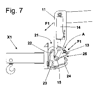
The swivel head 13 is made rotate, by means of the actuator 14, so as to move
it to its raised position A, and the support frame 11 is made translate
downwards in an inclined direction (arrows F1 in Figure 7), by suitable
operation of the lifter arm S, which allows the swivel head 13 and the first
gudgeon 15 to pass in the calibrated inlet opening 25 so as to fit in the
shaped
body 21 (Figure 7).
When the first gudgeon 15 strikes the bottom of said shaped body 21, the
swivel head 13 begins to oscillate downwards (arrow F2 in Figure 8), due to
the
actuator 14 action; the start of this operation is allowed by the fact that
the
winglet 18 is inside the stop 24 and does not interfere with it (Figure 8).
The support frame 11 is made translate from the bottom upwards, in step
relation with further downward oscillation of the swivel head 13, which
determines the progressive lifting of the first gudgeon 15 toward the support
means 22 (Figs. 9, 10).
When the swivel head 13 reaches its lowered position B, its front side is
struck
by the edge 26, while the protruding portions of said first gudgeon 15 go in
abutment against the lower part of the support means 22 (Figure 11); in this
condition, the lifter arm S is already capable of lifting the tool X1.
In the enclosed figures, the shaped body 21 advantageously includes a step
27, aimed at going in abutment against the lower part of the winglet 18, when
the swivel head 13 is in the just described position (see the enlarged detail
of
Figure 11);
The joining procedure is completed by engaging the movable element 17 of the
6
CA 02791234 2012-08-27
WO 2011/121400 PCT/IB2011/000258
second gudgeon 16 with the fastening eyelets 23, which are coaxial.
With the constructive solution that includes the opposed pins 171, 172, the
engagement is obtained by operating suitably the actuator 173 (Figure 12);
while the introduction of the rod 174, as it has already been said, is
performed
manually.
At this point, said second joining means 20 is integral with the swivel head
13,
therefore the tool X1 can oscillate on a vertical plane (arrows F3 in Figure
13)
with respect to the same articulation pivot 12 of the latter, due to the
action of
said actuator 14 (Figure 13).
The oscillation of the tool X1 is obviously controlled according to the
working
requirements and the inclination of the lifter arm S.
In case, in which the joining procedure is not completed with the engagement
of the movable element 17 with the fastening eyelets 23, the cantilevered
weight of the tool X1 (and of the possible load fastened thereto) keeps the
edge
26 in abutment against the swivel head 13, thus, in absence of external
factors,
the swiveling of the tool X1, by means of the actuator 14, is possible all the
same.
The quick connection 1 described hereto does not risk to uncouple casually
even if, without the movable element 17 being introduced, anomalous external
stresses act on the tool, for example for the impact against an obstacle; in
the
most disadvantageous situation, illustrated in Figure 14, the lifter arm S is
close
to the vertical, while the tool X1 is stressed by a tilting torque (arrow F4)
that
results in a relative rotation between the shaped body 21 and the swivel head
that tends to go out from the latter; such an event is prevented by the
interception of the stop 24 by means of the winglet 18 (see again Figure 14).
7
CA 02791234 2012-08-27
WO 2011/121400 PCT/IB2011/000258
In practice, the going out of the swivel head 13 is prevented in any
succession
of movements which are not inversely equal to those carried out for said
introduction.
The quick safety connection 1 can advantageously include a device aimed at
automatically identifying the kind of tool that is joined to the machine M,
for
example to adjust, again in automatic way, the operating parameters of the
latter.
Said identifying device, for example, can be of the type consisting of a
detection module 50, associated to the support frame 11, aimed at RF
interacting with an identifying module 51 associated to the shaped body 21
(Figure 5).
The identifying module 51 is preferably a so-called passive transponder that
does not contain a power source and is activated by the electromagnetic field
emitted by the antenna of the detection module 50, when the distance between
the two is sufficiently short.
The above description make appear clearly the positive characteristics of the
quick connection under discussion that fully obtains all the indicated
objects, in
particular offering, in any situation, the maximum safety against casual
uncoupling.
The tool engaging and disengaging operations are simple and rapid, and the
operator, who controls them, does not have to intervene manually during the
introduction or removal of the swivel head into or from the shaped body,
reducing to a minimum any accident risk.
The conformation of the joining means, either those associated to the tool or
those associated to the arm, ensures a safe functionality in difficult climate
8
CA 02791234 2012-08-27
WO 2011/121400 PCT/IB2011/000258
conditions and/or in presence of dirt, mud or other.
The second joining means associated to the tool does not have any moveable
part and consequently, it is suitable for resting outdoors even for long
periods
of time, without jeopardizing its subsequent re-use.
It is understood that what above has only illustrative and not limiting value,
therefore all possible detail modifications applied to the first and/or second
joining means for technical and/or functional reasons, are considered since
now within the protective scope defined by the claims reported below.
9