Language selection

Search

Patent 2791305 Summary

Third-party information liability

Some of the information on this Web page has been provided by external sources. The Government of Canada is not responsible for the accuracy, reliability or currency of the information supplied by external sources. Users wishing to rely upon this information should consult directly with the source of the information. Content provided by external sources is not subject to official languages, privacy and accessibility requirements.

Claims and Abstract availability

Any discrepancies in the text and image of the Claims and Abstract are due to differing posting times. Text of the Claims and Abstract are posted:

  • At the time the application is open to public inspection;
  • At the time of issue of the patent (grant).
(12) Patent Application: (11) CA 2791305
(54) English Title: L.P.G. VAPORIZER FOR PROPANE, BUTANE ETC. FOR GAS BURNING EQUIPMENT
(54) French Title: VAPORISATEUR DE GAZ DE PETROLE LIQUEFIES POUR LE PROPANE, LE BUTANE, ETC. POUR UN EQUIPEMENT DE COMBUSTION DE GAZ
Status: Deemed Abandoned and Beyond the Period of Reinstatement - Pending Response to Notice of Disregarded Communication
Bibliographic Data
Abstracts

English Abstract


The vaporizer changes liquified petroleum gas ( propane, butane,etc. ) to
vapor for gas
burning equipment. The vaporizer is installed downstream from the liquified
petroleum
gas (L.P.G.) supply tank and before the utilizing gas equipment (eg.,
industrial &
construction heating, grain dryers ,asphalt heating etc.).


Claims

Note: Claims are shown in the official language in which they were submitted.

I claim
1. A vaporizer that vaporizes liquid propane and other natural gas liquids
to vapor
using a heat exchanger coil in a water bath heated with an infra-red burner.
2. The burner is fueled from the outlet side of the vaporizer through a
pressure
reducing regulator.
3. The infra-red surface is made from sintered metallic metal.
4. The burner is a vertical tube type heater that radiates heat in 360 to
the
cylindrical shaped water bath.
5. The burner is located in the center of the water bath.
6. The vaporizer has a bypass line from the top of the propane tank which
supplies vapor to the outlet side of the vaporizer. This supplies fuel for
start-up.
7. The vapor line draws of the very light hydrocarbons preventing the
relief valves
from discharging in extreme hot weather.
8. A pressure sensor shuts down the the by-pass line when the pressure is
down to
about 80 p.s.i.g. , and the vaporizer starts to supply the gas automatically.
9. The vaporizer supplies gas at a constant temperature and pressure,
facilitating
complete combustion and b.t.u input.
10. A filter located downstream of the of the operating regulator separates
the
compressor oil and pipe line rouge .
11 The filter contains molecular sieve and a screen.
12 A regulator at the inlet of the vaporizer reduces the pressure to about
50 p.s.i.g.
and the LPG enthalpy vaporizes 15 %, increasing the capacity of the vaporizer.

13 A high pressure inspirator which uses a venturi to mix the propane and
air under
high pressure conditions required to push the mixture through the sintered
material.
14 The heater contains an infrared heating surface with a sintered metallic
material.
15 The heater contains a layer of skein above the infrared heating surface
to
produce an even flow through the infrared heating surface.
16 The heater contains expanded metal which retains the skein.
17 The sintered metal mesh, skein and expanded metal are installed in a
sealed
metal hood which is built to withstand the high pressure produced by the
orifice and
venturi.
18 The vaporizer is designed to operate with a wide range of grades of
propane.

Description

Note: Descriptions are shown in the official language in which they were submitted.


CA 02791305 2012-10-15
II
L.P.G. VAPORIZER FOR PROPANE, BUTANE ETC.
FOR GAS BURNING EQUIPMENT
_
Description oi the Prior Art
- -VapOrizers for liquid propane and other liquid petroleum
gases- exist Most vaporizers use pressure vessels. Liquid
propane expands as it cools and pressure is reduced. The
- pressure.:vessel is usually heated with direct Baum to vapor-
ize the propane. Over time, a residue accumulates in the
pressure tank. Usually, the pressure vessel has a temperature
sensing device to control the temperature of the liquid and
a float to prevent liquid nom exiting Arm& the outlet of the
vaporizer. Pressure vessels are expensive and they can be
dangerous to operate.
Propane vaporizers used in motor vehicles for carburetion
are quite small. Water from the cooling system of the motor
vehicle is used to vaporize the liquid fuel.
SUMMARY OF THE INVENTION
It is an object of the present invention to ptovide a
vaporizer that operates at low pressure. It is a further-object
of the present invention to provide a vaporizer that vaporizes
liquid petroleum gas from a high pressure supply aild is
suitable for operntion on a small scale.
A vaporizer is used with a supply of liquid petroleum-gas.
The vaporizer has a helical coil with an inlet and an-outlet:
The inlet of the coil is connected to the supply of liquid
petroleum gas and the liquid petroleum gas is substantially
vaporized in the call. The outlet is connected to a fuel
powered device and there are control means to control the
flow of petroleum gas from the supply through the coil to the
fuel powered device. The coil is located within a housing
containing a bath and the coil is immersed in the bath with
heating means to heat the cod

CA 02791305 2012-10-15
Vaporizer and Heater Patent Application
Description of the Invention
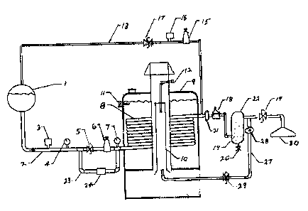
Fig. 1 is a schematic side view of the vaporizer
Fig. 2 is circuit diagram for the vaporizer
The liquified petroleum gas flows from the fuel tank 1 through a supply line
2.
The supply line has a hydrostatic relief valve 3 and a pressure gauge 4.
The pressure of the liquified petroleum gas (L.P.gas) is reduced with a liquid
regulator 6
to about 50 p.s.i.g. The enthalpy of the LPG vaporizes about 15% of the liquid
propane. The pressure gauge 4 is required to adjust the regulator to the
desired
pressure. The propane then flows through a heat exchanger coil 8 The coil is
located in
a water bath 9 , where the balance of the liquid L.P.G. is vaporized. The
water bath 9 is
heated with an infra-red burner 10. The burner is made from sintered metallic
material.
The burner is fueled from the outlet side of the vaporizer A temperature
sensor 11
controls the water bath temperature to the desired temperature. A gas line 27
with
regulator 28 and a solenoid valve 29 supply gas to the burner 10 which is
ignited by a
flame rod 12. A vapor line from the top of the propane tank 1 to the outlet of
the
vaporizer by-passes the vaporizer. This by-pass line burns off the light end
of the
carbon chain and prevents the relief valves form discharging in extreme hot
weather.
When the pressure is reduced by regulator 15 to about 80 p.s.i.g. the pressure
sensor 16 closes valve 17 and the vaporizer takes over.
The pressure reduction in the fuel tank prevents the tank relief valve from
discharging in
extreme hot weather. On the outlet side of the vaporizer, a regulator 18
controls the

CA 02791305 2012-10-15
pressure to the requirement of utilizing equipment 30. The gas then is
filtered through
a filter 22 which has a molecular sieve and screen 19 which separates the
compressor oil and pipe line rouge, and which is drained through valve 20.
When the
vaporizer is shut down valves 5, 17, 31 close trapping liquid in the heat
exchanger.
The liquid L.P.G. which is trapped in the heat exchanger coil 8 flows back to
the fuel
tank 1 through a by-pass line 23 with back check valve 24. Should the sensor
21 sense
a temperature below the operating temperature it would shut down the
vaporizer,
indicating flame-out. The vaporizer would then have to be manually started.
To start the vaporizer the operator would push the momentary switch Fig 2
(35). This
would close relay switch Fig 2 (32) starting the vaporizer. A by pass timer
Fig 2 (33)
would by pass sensor Fig 1 (21). This would allow the vaporizer to reach
operating
temperature and sensor Fig 1 ( 21) would close the circuit and the vaporizer
would
continue to operate. Fig 2 (34) is the control panel. Fig . 3 (36) is the
orifice and
Fig. (37) is the venturi tube.
Fig.3 (38) is the infra-red heating surface.

Representative Drawing
A single figure which represents the drawing illustrating the invention.
Administrative Status

2024-08-01:As part of the Next Generation Patents (NGP) transition, the Canadian Patents Database (CPD) now contains a more detailed Event History, which replicates the Event Log of our new back-office solution.

Please note that "Inactive:" events refers to events no longer in use in our new back-office solution.

For a clearer understanding of the status of the application/patent presented on this page, the site Disclaimer , as well as the definitions for Patent , Event History , Maintenance Fee  and Payment History  should be consulted.

Event History

Description Date
Time Limit for Reversal Expired 2017-10-17
Application Not Reinstated by Deadline 2017-10-17
Inactive: Abandon-RFE+Late fee unpaid-Correspondence sent 2017-10-16
Inactive: Correspondence - Prosecution 2017-08-03
Inactive: Correspondence - Prosecution 2017-07-31
Amendment Received - Voluntary Amendment 2017-07-24
Inactive: Correspondence - MF 2017-07-24
Inactive: Correspondence - MF 2017-07-17
Amendment Received - Voluntary Amendment 2017-07-17
Inactive: Correspondence - MF 2017-07-17
Amendment Received - Voluntary Amendment 2017-07-17
Inactive: Office letter 2017-07-05
Deemed Abandoned - Failure to Respond to Maintenance Fee Notice 2016-10-17
Maintenance Request Received 2015-09-18
Maintenance Request Received 2014-09-15
Application Published (Open to Public Inspection) 2014-04-15
Inactive: Cover page published 2014-04-14
Inactive: IPC assigned 2012-11-16
Inactive: First IPC assigned 2012-11-16
Inactive: Inventor deleted 2012-11-14
Inactive: Correspondence - Formalities 2012-11-05
Application Received - Regular National 2012-10-16
Inactive: Request under s.37 Rules - Non-PCT 2012-10-16
Reinstatement Requirements Deemed Compliant for All Abandonment Reasons 2012-10-16
Inactive: Filing certificate - No RFE (English) 2012-10-16
Small Entity Declaration Determined Compliant 2012-10-15

Abandonment History

Abandonment Date Reason Reinstatement Date
2016-10-17

Maintenance Fee

The last payment was received on 2015-09-18

Note : If the full payment has not been received on or before the date indicated, a further fee may be required which may be one of the following

  • the reinstatement fee;
  • the late payment fee; or
  • additional fee to reverse deemed expiry.

Patent fees are adjusted on the 1st of January every year. The amounts above are the current amounts if received by December 31 of the current year.
Please refer to the CIPO Patent Fees web page to see all current fee amounts.

Fee History

Fee Type Anniversary Year Due Date Paid Date
Application fee - small 2012-10-15
MF (application, 2nd anniv.) - small 02 2014-10-15 2014-09-15
MF (application, 3rd anniv.) - standard 03 2015-10-15 2015-09-18
Owners on Record

Note: Records showing the ownership history in alphabetical order.

Current Owners on Record
ALLEN A. NEUFELDT
Past Owners on Record
None
Past Owners that do not appear in the "Owners on Record" listing will appear in other documentation within the application.
Documents

To view selected files, please enter reCAPTCHA code :


To view images, click a link in the Document Description column. To download the documents, select one or more checkboxes in the first column and then click the "Download Selected in PDF format (Zip Archive)" or the "Download Selected as Single PDF" button.

List of published and non-published patent-specific documents on the CPD .

If you have any difficulty accessing content, you can call the Client Service Centre at 1-866-997-1936 or send them an e-mail at CIPO Client Service Centre.


Document
Description 
Date
(yyyy-mm-dd) 
Number of pages   Size of Image (KB) 
Representative drawing 2014-02-27 1 18
Claims 2012-10-14 2 52
Description 2012-10-14 3 124
Abstract 2012-10-14 1 10
Drawings 2012-10-14 3 85
Filing Certificate (English) 2012-10-15 1 156
Notice: Maintenance Fee Reminder 2014-07-15 1 120
Notice: Maintenance Fee Reminder 2015-07-15 1 127
Notice: Maintenance Fee Reminder 2016-07-17 1 121
Courtesy - Abandonment Letter (Maintenance Fee) 2016-11-27 1 172
Second Notice: Maintenance Fee Reminder 2017-04-18 1 130
Reminder - Request for Examination 2017-06-18 1 119
Notice: Maintenance Fee Reminder 2017-07-17 1 119
Courtesy - Abandonment Letter (Request for Examination) 2017-11-26 1 163
Correspondence 2012-10-15 2 40
Correspondence 2012-10-15 1 24
Correspondence 2012-11-04 3 103
Fees 2014-09-18 3 51
Maintenance fee payment 2015-09-17 1 22
Courtesy - Office Letter 2017-07-04 2 72
Amendment / response to report 2017-07-16 5 171
Maintenance fee correspondence 2017-07-16 5 171
Amendment / response to report 2017-07-16 5 170
Maintenance fee correspondence 2017-07-16 5 171
Amendment / response to report 2017-07-16 5 171
Maintenance fee correspondence 2017-07-16 5 171
Amendment / response to report 2017-07-23 3 97
Maintenance fee correspondence 2017-07-23 3 99
Prosecution correspondence 2017-07-30 1 28
Prosecution correspondence 2017-08-02 1 26
Amendment / response to report 2017-08-08 12 335