Language selection

Search

Patent 2791372 Summary

Third-party information liability

Some of the information on this Web page has been provided by external sources. The Government of Canada is not responsible for the accuracy, reliability or currency of the information supplied by external sources. Users wishing to rely upon this information should consult directly with the source of the information. Content provided by external sources is not subject to official languages, privacy and accessibility requirements.

Claims and Abstract availability

Any discrepancies in the text and image of the Claims and Abstract are due to differing posting times. Text of the Claims and Abstract are posted:

  • At the time the application is open to public inspection;
  • At the time of issue of the patent (grant).
(12) Patent: (11) CA 2791372
(54) English Title: CHROMATOGRAPHY COLUMN ASSEMBLY COMPRISING A FIXTURE FOR A PLASTIC MESH
(54) French Title: ENSEMBLE DE COLONNE CHROMATOGRAPHIQUE COMPRENANT UN DISPOSITIF DE FIXATION D'UN MAILLAGE EN PLASTIQUE
Status: Granted and Issued
Bibliographic Data
(51) International Patent Classification (IPC):
  • G01N 30/60 (2006.01)
  • B01D 15/22 (2006.01)
(72) Inventors :
  • SALOMONSSON, DANIEL (Sweden)
  • BENNEMO, PETTER (Sweden)
  • USELIUS, PER (Sweden)
(73) Owners :
  • CYTIVA SWEDEN AB
(71) Applicants :
  • CYTIVA SWEDEN AB (Sweden)
(74) Agent: SMART & BIGGAR LP
(74) Associate agent:
(45) Issued: 2018-08-14
(86) PCT Filing Date: 2011-03-10
(87) Open to Public Inspection: 2011-09-15
Examination requested: 2016-02-10
Availability of licence: N/A
Dedicated to the Public: N/A
(25) Language of filing: English

Patent Cooperation Treaty (PCT): Yes
(86) PCT Filing Number: PCT/SE2011/050261
(87) International Publication Number: SE2011050261
(85) National Entry: 2012-08-28

(30) Application Priority Data:
Application No. Country/Territory Date
1000230-1 (Sweden) 2010-03-12

Abstracts

English Abstract

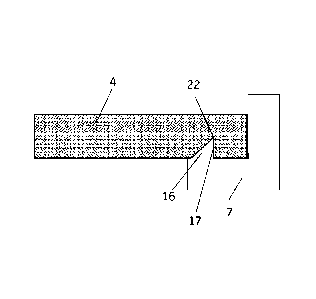
In a chromatography column, at least one plastic retaining mesh is attached to a distributor plate using a fixture element comprising an elongated edge that penetrates into the plastic mesh to ensure sealing and to prevent radial movement of the plastic mesh.


French Abstract

Dans une colonne chromatographique, au moins un maillage de rétention en plastique est fixé à une plaque de distribution en utilisant un élément de fixation comprenant un bord allongé pénétrant à l'intérieur du maillage en plastique afin d'en assurer l'étanchéité et d'empêcher tout mouvement radial du maillage en plastique.

Claims

Note: Claims are shown in the official language in which they were submitted.


CLAIMS:
1. A snap ring for securing a plastic mesh to a distributor plate in a
chromatography column assembly,
wherein said snap ring is prepared from an elastically deformable material and
comprises an edge
capable of penetrating into the plastic mesh and a snap-on protrusion arranged
to fit into a recess on
the perimeter of said distributor plate.
2. A snap ring according to claim 1, wherein the elastically deformable
material is a polyolefin.
3. A snap ring according to claim 1 or 2, wherein the edge has a height of at
least 0.2 mm or at least
0.5 mm.
4. A snap ring according to any one of claims 1-3, wherein the edge is sharp,
with a radius of
curvature less than 0.1 mm at the tip.
5. A snap ring according to any one of claims 1-4, wherein the edge has an
essentially triangular cross
section with one side essentially perpendicular to the plastic mesh.
6. A chromatography column assembly comprising at least one plastic mesh and
at least one fixture
element attaching said plastic mesh to a distributor plate, wherein said
fixture comprises an edge
penetrating into the plastic mesh to provide sealing and to prevent radial
movement of the plastic
mesh, wherein the fixture element is a snap ring according to claim 1.
7. A chromatography column assembly according to claim 6, wherein the edge
penetrates at least 0.1
mm or 0.5 mm into the plastic mesh.
8. A chromatography column assembly according to claim 6 or 7, wherein the
plastic mesh is a plastic
sinter mesh.
9. A chromatography column assembly according to any one of claims 6-8,
wherein the plastic mesh
comprises a polyolefin material.
10.A chromatography column assembly according to claim 9 wherein the
polyolefin material is a
polyethylene.
11. A chromatography column assembly according to any one of claims 6-9,
wherein the diameter of
the plastic mesh is at least 10 cm or at least 40 cm.
6

Description

Note: Descriptions are shown in the official language in which they were submitted.


CA 02791372 2012-08-28
WO 2011/112144 PCT/SE2011/050261
CHROMATOGRAPHY COLUMN ASSEMBLY COMPRISING A FIXTURE FOR A PLASTIC MESH
Technical field
The present invention relates generally to separation and specifically to
chromatographic
separation of biomolecules. More particularly the invention relates to
fixtures for plastic meshes
in chromatography columns and column assemblies comprising such fixtures.
Background of the invention
Chromatography columns may be used in industrial processes to purify process
liquids and
separate substances of interested from process liquids. Prior art
chromatography columns
comprise a column wall in the form of hollow column tube which is connected to
a removable
upper end plate assembly and a removable lower end plate assembly. One end
plate assembly is
provided with a process fluid inlet arrangement, typically comprising an inlet
pipe and an inlet
valve and the other end plate assembly is provided with a process fluid outlet
arrangement,
typically comprising an outlet pipe and an outlet valve. Each end of the
column tube is usually
provided in the interior of the column with a removable distributor plate.
These inlet and outlet
distributor plates may be attached to the respective end plate assembly or the
upper distributor
plate may be arranged to be movable towards or away from the end plate
assembly. During use,
the space in the column between the distributor plates is usually filled with
a chromatography
medium. A retaining mesh is normally provided between each distribution system
and the media
in order to prevent media particles from escaping the column. The inlet
distributor plate is
intended to distribute incoming fluid evenly over the surface of the media at
the inlet end of the
column while the outlet distributor plate is intended to collect fluid evenly
from the surface of
the media at the outlet end of the column. Such a column may weigh several
tons.
The retaining meshes extend across substantially the whole internal diameter
of the column and
are normally fixed along the outer perimeter of the column and at the center
of the column. The
meshes can be prepared from woven threads of either metals or polymers or they
can be made
from sintered particles. They can also be multilayer constructions of e.g.
several woven meshes
joined by sintering. During maintenance of the column it is desirable that the
retaining mesh can
be easily exchanged for a new one with an arrangement providing good sealing
and no stagnant
zones that may impair sanitation of the column. EP008921(A1) describes a
structure with snap
ring action for fixing a polyethylene sinter mesh but this solution does not
satisfy current needs
for sealing and sanitation. There is thus a need for further improvements in
this regard.
PR'= i0 ,Hi1.=P ;iz;= 1

81559062
Brief description of the invention
One aspect of the present invention is to provide a secure, non-leaking and
sanitary attachment of a
plastic mesh to a distributor plate or a support ring. This is achieved with a
fixture element for securing a
plastic mesh to a distributor plate in a chromatography column assembly,
wherein said fixture element
comprises an edge intended to penetrate into the plastic mesh. It is also
achieved with a chromatography
column assembly comprising at least one plastic mesh and at least one fixture
element attaching said
plastic mesh to a distributor plate wherein said fixture element comprises an
edge penetrating into the
plastic mesh to provide sealing and to prevent radial movement of the plastic
mesh. In other words, an
elongated edge on the fixture element penetrates into the plastic mesh during
assembly and provides
sealing and fixation of the plastic mesh with minimal stagnant deadleg
volumes.
Another aspect of the present invention is to provide a snap ring for securing
a plastic mesh to a distributor
plate in a chromatography column assembly, wherein said snap ring is prepared
from an elastically
deformable material and comprises an edge capable of penetrating into the
plastic mesh and a snap-on
protrusion arranged to fit into a recess on the perimeter of said distributor
plate.
Brief description of the drawinEs
Figure 1 shows a schematic view of a chromatography column in cross section.
Figure 2 shows an adaptor distributor plate and a plastic mesh according to
one embodiment of the
invention.
Figure 3 shows an enlargement of area A in Figure 2, according to one
embodiment of the invention.
Figure 4 shows an enlargement of area B in Figure 2, according to one
embodiment of the invention.
Figure 5 shows an overview of a column tube with a plastic retaining mesh and
a bottom distributor
plate, according to one embodiment of the invention.
Figure 6 shows an enlargement of area C in figure 5, according to one
embodiment of the invention.
Figure 7 shows a further enlargement of area D in Figure 6, according to one
embodiment of the invention.
Figure 8 shows a plastic mesh and a fixture element according to one
embodiment of the invention.
Figure 9 shows a snap ring with an edge, according to one embodiment of the
invention.
Definitions
The term "mesh" means herein any porous material in sheet form that can be
used to retain
chromatography media in a column. Meshes can be made from e.g. woven threads,
entanglements
of non-woven threads, sintered particles, stretched sheets etc and the
materials
2
CA 2791372 2018-03-06

CA 02791372 2012-08-28
WO 2011/112144 PCT/SE2011/050261
used can be e.g. metals, polymers, glasses or ceramics. In a plastic mesh, the
material comprises
a polymer.
Detailed description of the invention
One embodiment of the invention, is a chromatography column assembly wherein
the edge
9,12,13,15, 16 of the fixture element 7 penetrates at least 0.1 mm or at least
0.5 mm into the
plastic mesh 4. Figure 1 shows a schematic view of a chromatography column
with column tube
1, adaptor backing plate 2, adaptor distributor plate 3, plastic meshes 4,
bottom distributor plate
5, bottom backing plate 6 and fixture elements 7.
In one embodiment the plastic mesh 4 is a plastic sinter mesh. Sinter meshes
are typically
prepared by heat compression of polymer powders in molds, allowing the
sintering of the
powder particles into a cohesive porous material. The pore size of the sinter
mesh can be
selected to be sufficiently small to retain the chromatography media particles
but not so small as
to give a large pressure drop over the mesh. Pore sizes between 7 and 150
microns can be
suitable for use in the invention. The thickness of the sinter mesh can be
from about 0.75 to
about 10 mm.
In one embodiment the plastic mesh 4 comprises a polyolefin material, such as
polyethylene.
Examples of polyolefin materials are polyethylene, polypropylene,
polybutylene, poly-
alfaolefins, cycloolefin polymers and any copolymers of ethylene, propylene,
butylene,
alfaolefins or cycloolefins. Specific examples of polyethylene are high
density polyethylene
(HDPE), low density polyethylene (LDPE), linear low density polyethylene
(LLDPE), ultralow
density polyethylene (ULDPE) and ultrahigh molecular weight polyethylene
(UHMWPE).
Examples of commercially available polyethylene sinter meshes are Vyon PE from
Porvair PLC
(UK) and POREX PE from Porex Corp (US). An advantage of using polyethylene is
that it is a
resilient flexible material available in high purity and it is soft enough to
allow penetration of
the fixture element edge.
In one embodiment, illustrated by Figures 3 and 9, the fixture element
comprises a snap ring 8.
The snap ring can be prepared from an elastically deformable material such as
a polyolefin, e.g.
polyethylene, so that it can be radially extended, applied over the perimeter
18 of the distributor
plate and the perimeter 19 of the plastic mesh and then allowed to snap back,
fixing the plastic
mesh to the distributor plate. A snap-on protrusion 20 on the snap ring can
then fit into a recess
21 on the perimeter of the distributor and keep the snap ring in an axial
position. The edge 9 on
'..FC)%3 =,1 I' ''''' 3

81559062
the snap ring may penetrate into the plastic mesh 4 during application of the
snap ring 8, but it is
also possible to ensure penetration by applying axial pressure on the snap
ring 8 with a suitable
tool afler application of the snap ring. The plastic mesh 4 may further
comprise a groove 10 for
partial accommodation of the snap ring edge 9, to allow for easier assembling.
The edge will
then penetrate into the mesh starting from the bottom of the groove 10,
In one embodiment, illustrated by Figure 4, the fixture element comprises a
screw 11. The screw
can be applied to a threaded hole (not shown) in the center of the distributor
plate and the edge
12 can be situated close to the perimeter of the screw 11 in such a way that
when the screw is
fastened, the edge will cut into the plastic mesh 4 and give the desired
sealing and fixation.
In one embodiment, illustrated by Figures 5, 6 and 7 the fixture element
comprises an integral
feature of a distributor plate 3,5. The integral feature can be an edge 13,15
protruding from the
surface of the distributor plate 3,5, so that when the plastic mesh 4 is
pressed against the
distributor plate, the edge penetrates into the mesh to achieve sealing and
fixation. An o-ring 14
can be used to provide additional sealing between the column tube 1 and the
bottom distributor
plate 5.
In one embodiment the diameter of the plastic mesh 4 is at least 10 cm or at
least 40 cm.
Handling of larger diameter meshes, which can be difficult using methods known
in the art, ir.
facilitated by the fixture elements of the invention. Demands for good sealing
and prevention of
radial movement are also accentuated for large diameter meshes, making the
fixture elements of
the invention particularly useful.
In one embodiment the edge 9,12,13,15, 16 on the fixture element 7 has a
height of at least 0,2
mm or at least 0.5 rum. An advantage ofa high edge is,that it ensures a
sufficient penetration
depth to ensure sealing and fixation.
In one embodiment, illustrated by Figure 8, the edge 16 is sharp, with a
radius of curvature less
than 0.1 mm, such as less than 0.01 nun, at the tip 22. A sharp edge with a
low radius of
curvature at the tip will facilitate penetration into the plastic mesh.
Inane embodiment, illustrated by Figure 8, the edge 16 has an essentially
triangular cross
section with one side 17 essentially perpendicular to the plastic mesh 4. An
advantage of this is
4
CA 2791372 2017-06-12

81559062
that it improves the radial fixation of the mesh, preventing lateral movement
particularly in the
direction towards the perpendicular side of the edge.
Other features and advantages of the invention will be apparent from the
claims.
This written description uses examples to disclose the invention, including
the best mode, and
also to enable any person skilled in the art to practice the invention,
including making and using
any devices or systems and performing any incorporated methods. The patentable
scope of the
invention is defined by the claims, and may include other examples that occur
to those skilled in
the art. Such other examples are intended to be within the scope of the claims
if they have
structural elements that do not differ from the literal language of the
claims, or if they include
equivalent structural elements with insubstantial differences from the literal
languages of the
claims.
While preferred illustrative embodiments of the present invention are
described, one
skilled in the art will appreciate that the present invention can be practiced
by other than the
described embodiments, which are presented for purposes of illustration only
and not by way
of limitation. The present invention is limited only by the claims that
follow.
5
CA 2791372 2017-06-12

Representative Drawing
A single figure which represents the drawing illustrating the invention.
Administrative Status

2024-08-01:As part of the Next Generation Patents (NGP) transition, the Canadian Patents Database (CPD) now contains a more detailed Event History, which replicates the Event Log of our new back-office solution.

Please note that "Inactive:" events refers to events no longer in use in our new back-office solution.

For a clearer understanding of the status of the application/patent presented on this page, the site Disclaimer , as well as the definitions for Patent , Event History , Maintenance Fee  and Payment History  should be consulted.

Event History

Description Date
Letter Sent 2020-10-28
Inactive: Multiple transfers 2020-10-07
Common Representative Appointed 2019-10-30
Grant by Issuance 2018-08-14
Inactive: Cover page published 2018-08-13
Pre-grant 2018-07-04
Inactive: Final fee received 2018-07-04
Notice of Allowance is Issued 2018-06-05
Letter Sent 2018-06-05
Notice of Allowance is Issued 2018-06-05
Inactive: Approved for allowance (AFA) 2018-05-29
Inactive: Q2 passed 2018-05-29
Amendment Received - Voluntary Amendment 2018-05-18
Examiner's Interview 2018-05-16
Inactive: Q2 failed 2018-05-10
Amendment Received - Voluntary Amendment 2018-03-06
Inactive: S.30(2) Rules - Examiner requisition 2017-09-06
Inactive: Report - No QC 2017-09-01
Amendment Received - Voluntary Amendment 2017-06-12
Inactive: S.30(2) Rules - Examiner requisition 2016-12-12
Inactive: Report - No QC 2016-12-09
Letter Sent 2016-02-15
All Requirements for Examination Determined Compliant 2016-02-10
Request for Examination Requirements Determined Compliant 2016-02-10
Request for Examination Received 2016-02-10
Change of Address or Method of Correspondence Request Received 2015-01-15
Inactive: Cover page published 2012-10-31
Inactive: First IPC assigned 2012-10-17
Inactive: Notice - National entry - No RFE 2012-10-17
Inactive: IPC assigned 2012-10-17
Application Received - PCT 2012-10-17
National Entry Requirements Determined Compliant 2012-08-28
Application Published (Open to Public Inspection) 2011-09-15

Abandonment History

There is no abandonment history.

Maintenance Fee

The last payment was received on 2018-02-21

Note : If the full payment has not been received on or before the date indicated, a further fee may be required which may be one of the following

  • the reinstatement fee;
  • the late payment fee; or
  • additional fee to reverse deemed expiry.

Patent fees are adjusted on the 1st of January every year. The amounts above are the current amounts if received by December 31 of the current year.
Please refer to the CIPO Patent Fees web page to see all current fee amounts.

Owners on Record

Note: Records showing the ownership history in alphabetical order.

Current Owners on Record
CYTIVA SWEDEN AB
Past Owners on Record
DANIEL SALOMONSSON
PER USELIUS
PETTER BENNEMO
Past Owners that do not appear in the "Owners on Record" listing will appear in other documentation within the application.
Documents

To view selected files, please enter reCAPTCHA code :


To view images, click a link in the Document Description column. To download the documents, select one or more checkboxes in the first column and then click the "Download Selected in PDF format (Zip Archive)" or the "Download Selected as Single PDF" button.

List of published and non-published patent-specific documents on the CPD .

If you have any difficulty accessing content, you can call the Client Service Centre at 1-866-997-1936 or send them an e-mail at CIPO Client Service Centre.


Document
Description 
Date
(yyyy-mm-dd) 
Number of pages   Size of Image (KB) 
Description 2017-06-11 5 235
Claims 2017-06-11 1 34
Description 2012-08-27 5 265
Drawings 2012-08-27 9 141
Representative drawing 2012-08-27 1 19
Claims 2012-08-27 1 51
Abstract 2012-08-27 2 76
Description 2018-03-07 5 238
Claims 2018-03-07 1 38
Claims 2018-05-17 1 39
Representative drawing 2018-07-16 1 17
Notice of National Entry 2012-10-16 1 193
Reminder of maintenance fee due 2012-11-13 1 111
Reminder - Request for Examination 2015-11-11 1 117
Acknowledgement of Request for Examination 2016-02-14 1 175
Commissioner's Notice - Application Found Allowable 2018-06-04 1 162
PCT 2012-08-27 16 470
Correspondence 2015-01-14 2 56
Request for examination 2016-02-09 2 80
Examiner Requisition 2016-12-11 4 233
Amendment / response to report 2017-06-11 8 306
Examiner Requisition 2017-09-05 3 169
Amendment / response to report 2018-03-05 4 171
Interview Record 2018-05-15 1 19
Amendment / response to report 2018-05-17 3 115
Final fee 2018-07-03 2 63