Note: Descriptions are shown in the official language in which they were submitted.
81643338
BONDED ABRASIVE WHEEL
TECHNICAL FIELD
The present disclosure relates to bonded abrasive articles.
BACKGROUND
Bonded abrasive articles have abrasive particles bonded together by a bonding
medium. Bonded abrasives include, for example, stones, hones, grinding wheels,
and cut-off
wheels. The bonding medium is typically an organic resin, but may also be an
inorganic
material such as a ceramic or glass (i.e., vitreous bonds).
Cut-off wheels are typically thin wheels used for general cutting operations.
The wheels are typically about 2 to about 100 centimeters in diameter, and
from less than one
millimeter (mm) to several mm thick. They are typically operated at speeds of
from about
1000 to about 50000 revolutions per minute, and are used for operations such
as cutting metal
or glass; for example, to a nominal length. Cut-off wheels are also known as
"industrial cut-
off saw blades" and, in some settings such as foundries, as "chop saws". As
their name
implies, cut-off wheels are use to cut stock such as, for example, metal rods,
by abrading
through the stock.
SUMMARY
According to an aspect of the present disclosure, there is provided a bonded
abrasive comprising ceramic shaped abrasive particles retained in a binder,
wherein each of
the ceramic shaped abrasive particles is respectively bounded by a polygonal
base, a
polygonal top substantially parallel to the base, and a plurality of sides
connecting the base
and the top, wherein adjacent sides meet at respective side edges having an
average radius of
curvature of less than 50 micrometers, wherein the bonded abrasive comprises a
bonded
abrasive wheel having opposed major surfaces, and wherein for a majority of
the ceramic
shaped abrasive particles, each respective base is aligned substantially
parallel to the opposed
major surfaces.
- 1 -
CA 2791475 2017-06-29
81643338
In another aspect, the present disclosure provides a bonded abrasive
comprising ceramic shaped abrasive particles retained in a binder, wherein
each of the
ceramic shaped abrasive particles is respectively bounded by a polygonal base,
a polygonal
top, and a plurality of sides connecting the base and the top, wherein
adjacent sides meet at
respective side edges having an average radius of curvature of less than 50
micrometers, and
wherein the bonded abrasive comprises a bonded abrasive wheel.
In some embodiments, the bonded abrasive further comprises crushed abrasive
particles having a specified nominal grade. In some embodiments, the crushed
abrasive
particles are of a finer abrasives industry recognized specified nominal grade
than the ceramic
shaped abrasive particles.
In some embodiments, the ceramic shaped abrasive particles nominally
comprise truncated triangular pyramids. In some embodiments, the ceramic
shaped abrasive
- la-
CA 2791475 2017-06-29
81643338
particles nominally comprise truncated regular triangular pyramids. In some
embodiments, the ceramic shaped abrasive particles have a ratio of maximum
length to
thickness of from 1:1 to 8:1. In some embodiments, the ceramic shaped abrasive
particles
have a ratio of maximum length to thickness of from 2:1 to 4:1. In some
embodiments,
each of the sides independently forms a respective dihedral angle with the
base in a range
of from 75 to 85 degrees.
In some embodiments, the ceramic shaped abrasive particles comprise sol-gel
derived alumina abrasive particles. In some embodiments, the ceramic shaped
abrasive
particles have a coating of inorganic particles thereon.
In some embodiments, the bonded abrasive wheel comprises reinforcing material
disposed on opposed major surfaces thereof. In some embodiments, the bonded
abrasive
wheel has opposed major surfaces, and wherein for a majority of the ceramic
shaped
abrasive particles, the base is aligned substantially parallel to the opposed
major surfaces.
In some embodiments, the binder comprises a phenolic resin. In some
embodiments, the
bonded abrasive wheel comprises a cut-off wheel. In some embodiments, the
bonded
abrasive wheel comprises a depressed-center grinding wheel (e.g., a Type 26,
27, or 28
depressed-center grinding wheel).
Advantageously, bonded abrasive wheels (e.g., cut-off wheels) according to the
present disclosure may exhibit superior cutting performance and/or product
longevity
during use. Such performance is unexpected inasmuch as that while sharper
edges may
lead to high initial cut, they would be expected to quickly dull during use.
As used herein, the term "shaped abrasive particle" refers to an abrasive
particle
with at least a portion of the abrasive particle having a nominal
predetermined shape
corresponding to a mold cavity used to form a precursor shaped abrasive
particle, which is
then calcined and sintered to form the shaped abrasive particle. Shaped
abrasive particle
as used herein excludes abrasive particles obtained by a mechanical crushing
operation.
As used herein, the term "nominal" means: of, being, or relating to a
designated or
theoretical size and/or shape that may vary from the actual.
Features and advantages of the present disclosure will be further understood
upon
consideration of the detailed description and drawings.
-2-
CA 2791475 2017-06-29
CA 02791475 2012-08-28
WO 2011/109188 PCT/US2011/025696
BRIEF DESCRIPTION OF THE DRAWINGS
FIG. 1 is a perspective view of an exemplary bonded abrasive cut-off wheel
according to one embodiment of the present disclosure;
FIG. 2 is a cross-sectional side view of exemplary bonded abrasive cut-off
wheel
shown in FIG. 1 taken along line 2-2;
FIG. 3A is a schematic top view of exemplary ceramic shaped abrasive particle
320;
FIG. 3B is a schematic side view of exemplary ceramic shaped abrasive particle
320;
FIG. 3C is a cross-sectional top view of plane 3-3 in FIG. 3B;
FIG. 3D is an enlarged view of side edge 327a in FIG. 3C; and
FIG. 4 is a perspective view of an exemplary depressed-center grinding wheel
according to one embodiment of the present disclosure.
While the above-identified drawing figures set forth several embodiments of
the
present disclosure, other embodiments are also contemplated, as noted in the
discussion.
The figures may not be drawn to scale. Like reference numbers may have been
used
throughout the figures to denote like parts.
DETAILED DESCRIPTION
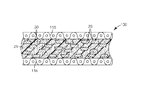
Referring now to FIG. 1, exemplary bonded abrasive cut-off wheel 100 according
to one embodiment of the present disclosure has center hole 112 used for
attaching cut-off
wheel 100 to, for example, a power driven tool. Cut-off wheel 100 includes
ceramic
shaped abrasive particles 20, optional conventionally crushed and sized
abrasive particles
30, and binder material 25.
FIG. 2 is a cross-section of cut-off wheel 100 of FIG. 1 taken along line 2-2,
showing sol-gel alumina based ceramic shaped abrasive particles 20, optional
conventionally-crushed abrasive particles 30, and binder material 25. Cut-off
wheel 100
has optional first scrim 115 and optional second scrim 116, which arc disposed
on opposed
major surfaces of cut-off wheel 100.
The bonded abrasive wheels according to the present disclosure are generally
made
by a molding process. During molding, a binder material precursor, either
liquid organic,
powdered inorganic, powdered organic, or a combination of thereof, is mixed
with the
-3-
CA 02791475 2012-08-28
WO 2011/109188 PCT/US2011/025696
abrasive particles. In some instances, a liquid medium (either resin or a
solvent) is first
applied to the abrasive particles to wet their outer surface, and then the
wetted particles are
mixed with a powdered medium. Bonded abrasive wheels according to the present
disclosure may be made by compression molding, injection molding, transfer
molding, or
the like. The molding can be done either by hot or cold pressing or any
suitable manner
known to those skilled in the art.
The binder material typically comprises a glassy inorganic material (e.g., as
in the
case of vitrified abrasive wheels), metal, or an organic resin (e.g., as in
the case of resin-
bonded abrasive wheels).
Glassy inorganic binders may be made from a mixture of different metal oxides.
Examples of these metal oxide vitreous binders include silica, alumina,
calcia, iron oxide,
titania, magnesia, sodium oxide, potassium oxide, lithium oxide, manganese
oxide, boron
oxide, phosphorous oxide, and the like. Specific examples of vitreous binders
based upon
weight include, for example, 47.61 percent Si02, 16.65 percent A1203, 0.38
percent Fe2
03, 0.35 percent Ti02, 1.58 percent CaO, 0.10 percent MgO, 9,63 percent Na2O,
2.86
percent K20, 1.77 percent Li20, 19.03 percent B203, 0.02 percent Mn02, and
0.22
percent P205 ; and 63 percent Si02, 12 percent A1203, 1.2 percent CaO, 6.3
percent
Na20, 7.5 percent K20, and 10 percent B203. During manufacture of a vitreous
bonded
abrasive wheel, the vitreous binder, in a powder form, may be mixed with a
temporary
binder, typically an organic binder. The vitrified binders may also be formed
from a frit,
for example anywhere from about one to 100 percent frit, but generally 20 to
100 percent
frit. Some examples of common materials used in frit binders include feldspar,
borax,
quartz, soda ash, zinc oxide, whiting, antimony trioxide, titanium dioxide,
sodium
silicofluoride, flint, cryolite, boric acid, and combinations thereof. These
materials are
usually mixed together as powders, fired to fuse the mixture and then the
fused mixture is
cooled. The cooled mixture is crushed and screened to a very fine powder to
then be used
as a frit binder. The temperature at which these frit bonds are matured is
dependent upon
its chemistry, but may range from anywhere from about 600 C to about 1800 C.
Examples of metal binders include tin, copper, aluminum, nickel, and
combinations thereof
-4-
CA 02791475 2012-08-28
WO 2011/109188 PCT/US2011/025696
Organic binder materials are typically included in an amount of from 5 to 30
percent, more typically 10 to 25, and more typically 15 to 24 percent by
weight, based of
the total weight of the bonded abrasive wheel. Phenolic resin is the most
commonly used
organic binder material, and may be used in both the powder form and liquid
state.
Although phenolic resins arc widely used, it is within the scope of this
disclosure to use
other organic binder materials including, for example, epoxy resins, urea-
formaldehyde
resins, rubbers, shellacs, and acrylic binders. The organic binder material
may also be
modified with other binder materials to improve or alter the properties of the
binder
material.
Useful phenolic resins include novolac and resole phenolic resins. Novolac
phenolic resins are characterized by being acid-catalyzed and having a ratio
of
formaldehyde to phenol of less than one, typically between 0.5:1 and 0.8:1.
Resole
phenolic resins are characterized by being alkaline catalyzed and having a
ratio of
formaldehyde to phenol of greater than or equal to one, typically from 1:1 to
3:1. Novolac
and resole phenolic resins may be chemically modified (e.g., by reaction with
epoxy
compounds), or they may be unmodified. Exemplary acidic catalysts suitable for
curing
phenolic resins include sulfuric, hydrochloric, phosphoric, oxalic, and p-
toluenesulfonic
acids. Alkaline catalysts suitable for curing phenolic resins include sodium
hydroxide,
barium hydroxide, potassium hydroxide, calcium hydroxide, organic amines, or
sodium
carbonate.
Phenolic resins are well-known and readily available from commercial sources.
Examples of commercially available novolac resins include DUREZ 1364, a two-
step,
powdered phenolic resin (marketed by Durez Corporation of Addison, Texas under
the
trade designation VARCUM (e.g., 29302), or HEXION AD5534 RESIN (marketed by
Hexion Specialty Chemicals, Inc. of Louisville, Kentucky). Examples of
commercially
available resole phenolic resins useful in practice of the present disclosure
include those
marketed by Durez Corporation under the trade designation VARCUM (e.g., 29217,
29306, 29318, 29338, 29353); those marketed by Ashland Chemical Co. of Bartow,
Florida under the trade designation AEROFENE (e.g., AEROFENE 295); and those
marketed by Kangnam Chemical Company Ltd. of Seoul, South Korea under the
trade
designation "PHENOLITE" (e.g., PHENOLITE TD-2207).
-5-
CA 02791475 2012-08-28
WO 2011/109188 PCT/US2011/025696
Curing temperatures of organic binder material precursors will vary with the
material chosen and wheel design. Selection of suitable conditions is within
the capability
of one of ordinary skill in the art. Exemplary conditions for a phenolic
binder may include
an applied pressure of about 20 tons per 4 inches diameter (224 kg/cm2) at
room
temperature followed by heating at temperatures up to about 185 C for
sufficient time to
cure the organic binder material precursor.
In some embodiments, the bonded abrasive wheels include from about 10 to 60
percent by weight of ceramic shaped abrasive particles; typically 30 to 60
percent by
weight, and more typically 40 to 60 percent by weight, based on the total
weight of the
binder material and abrasive particles.
Ceramic shaped abrasive particles composed of crystallites of alpha alumina,
magnesium alumina spinel, and a rare earth hexagonal aluminate may be prepared
using
sol-gel precursor alpha alumina particles according to methods described in,
for example,
U.S. Patent No. 5,213,591 (Celikkaya et al.) and U.S. Publ. Patent Appl. Nos.
2009/0165394 Al (Culler et al.) and 2009/0169816 Al (Erickson et al.).
In some embodiments, alpha alumina based ceramic shaped abrasive particles can
be made according to a multistep process. Briefly, the method comprises the
steps of
making either a seeded or non-seeded sol-gel alpha alumina precursor
dispersion that can
be converted into alpha alumina; filling one or more mold cavities having the
desired outer
shape of the shaped abrasive particle with the sol-gel, drying the sol-gel to
form precursor
ceramic shaped abrasive particles; removing the precursor ceramic shaped
abrasive
particles from the mold cavities; calcining the precursor ceramic shaped
abrasive particles
to form calcined, precursor ceramic shaped abrasive particles, and then
sintering the
calcined, precursor ceramic shaped abrasive particles to form ceramic shaped
abrasive
particles. The process will now be described in greater detail.
The first process step involves providing either a seeded or non-seeded
dispersion
of an alpha alumina precursor that can be converted into alpha alumina. The
alpha
alumina precursor dispersion often comprises a liquid that is a volatile
component. In one
embodiment, the volatile component is water. The dispersion should comprise a
sufficient
amount of liquid for the viscosity of the dispersion to be sufficiently low to
enable filling
mold cavities and replicating the mold surfaces, but not so much liquid as to
cause
subsequent removal of the liquid from the mold cavity to be prohibitively
expensive. In
-6-
CA 02791475 2012-08-28
WO 2011/109188 PCT/US2011/025696
one embodiment, the alpha alumina precursor dispersion comprises from 2
percent to 90
percent by weight of the particles that can be converted into alpha alumina,
such as
particles of aluminum oxide monohydrate (boehmite), and at least 10 percent by
weight, or
from 50 percent to 70 percent, or 50 percent to 60 percent, by weight of the
volatile
component such as water. Conversely, the alpha alumina precursor dispersion in
some
embodiments contains from 30 percent to 50 percent, or 40 percent to 50
percent, by
weight solids.
Aluminum oxide hydrates other than boehmite can also be used. Boehmite can be
prepared by known techniques or can be obtained commercially. Examples of
commercially available boehmite include products having the trade designations
"DISPERAL", and "DISPAL", both available from Sasol North America, Inc. of
Houston,
Texas, or "HiQ-40" available from BASF Corporation of Florham Park, New
Jersey.
These aluminum oxide monohydrates are relatively pure; that is, they include
relatively
little, if any, hydrate phases other than monohydrates, and have a high
surface area.
The physical properties of the resulting ceramic shaped abrasive particles
will
generally depend upon the type of material used in the alpha alumina precursor
dispersion.
In one embodiment, the alpha alumina precursor dispersion is in a gel state.
As used
herein, a "gel" is a three dimensional network of solids dispersed in a
liquid.
The alpha alumina precursor dispersion may contain a modifying additive or
precursor of a modifying additive. The modifying additive can function to
enhance some
desirable property of the abrasive particles or increase the effectiveness of
the subsequent
sintering step. Modifying additives or precursors of modifying additives can
be in the
form of soluble salts, typically water soluble salts. They typically consist
of a metal-
containing compound and can be a precursor of oxide of magnesium, zinc, iron,
silicon,
cobalt, nickel, zirconium, hafnium, chromium, yttrium, praseodymium, samarium,
ytterbium, neodymium, lanthanum, gadolinium, cerium, dysprosium, erbium,
titanium,
and mixtures thereof. The particular concentrations of these additives that
can be present
in the alpha alumina precursor dispersion can be varied based on skill in the
art.
Typically, the introduction of a modifying additive or precursor of a
modifying
additive will cause the alpha alumina precursor dispersion to gel. The alpha
alumina
precursor dispersion can also be induced to gel by application of heat over a
period of
time. The alpha alumina precursor dispersion can also contain a nucleating
agent
-7-
CA 02791475 2012-08-28
WO 2011/109188 PCT/US2011/025696
(seeding) to enhance the transformation of hydrated or calcined aluminum oxide
to alpha
alumina. Nucleating agents suitable for this disclosure include fine particles
of alpha
alumina, alpha ferric oxide or its precursor, titanium oxides and titanates,
chrome oxides,
or any other material that will nucleate the transformation. The amount of
nucleating
agent, if used, should be sufficient to effect the transformation of alpha
alumina.
Nucleating such alpha alumina precursor dispersions is disclosed in U.S.
Patent No.
4,744,802 (Schwabel).
A peptizing agent can be added to the alpha alumina precursor dispersion to
produce a more stable hydrosol or colloidal alpha alumina precursor
dispersion. Suitable
peptizing agents are monoprotic acids or acid compounds such as acetic acid,
hydrochloric
acid, formic acid, and nitric acid. Multiprotic acids can also be used but
they can rapidly
gel the alpha alumina precursor dispersion, making it difficult to handle or
to introduce
additional components thereto. Some commercial sources of boehmite contain an
acid
titer (such as absorbed formic or nitric acid) that will assist in forming a
stable alpha
alumina precursor dispersion.
The alpha alumina precursor dispersion can be formed by any suitable means,
such
as, for example, by simply mixing aluminum oxide monohydrate with water
containing a
peptizing agent or by forming an aluminum oxide monohydrate slurry to which
the
peptizing agent is added.
Defoamers or other suitable chemicals can be added to reduce the tendency to
form
bubbles or entrain air while mixing. Additional chemicals such as wetting
agents,
alcohols, or coupling agents can be added if desired. The alpha alumina
abrasive particles
may contain silica and iron oxide as disclosed in U.S. Patent No. 5,645,619
(Erickson et
al.). The alpha alumina abrasive particles may contain zirconia as disclosed
in U.S. Patent
No. 5,551,963 (Larmie). Alternatively, the alpha alumina abrasive particles
can have a
microstructure or additives as disclosed in U.S. Patent No. 6,277,161
(Castro).
The second process step involves providing a mold having at least one mold
cavity, and preferably a plurality of cavities. The mold can have a generally
planar bottom
surface and a plurality of mold cavities. The plurality of cavities can be
formed in a
production tool. The production tool can be a belt, a sheet, a continuous web,
a coating
roll such as a rotogravure roll, a sleeve mounted on a coating roll, or die.
In one
embodiment, the production tool comprises polymeric material. Examples of
suitable
-8-
CA 02791475 2012-08-28
WO 2011/109188
PCT/US2011/025696
polymeric materials include thermoplastics such as polyesters, polycarbonates,
poly(ether
sulfone), poly(methyl methacrylate), polyurethanes, polyvinylchloride,
polyolefin,
polystyrene, polypropylene, polyethylene or combinations thereof, or
thermosetting
materials. In one embodiment, the entire tooling is made from a polymeric or
thermoplastic material. In another embodiment, the surfaces of the tooling in
contact with
the sol-gel while drying, such as the surfaces of the plurality of cavities,
comprises
polymeric or thermoplastic materials and other portions of the tooling can be
made from
other materials. A suitable polymeric coating may be applied to a metal
tooling to change
its surface tension properties by way of example.
A polymeric or thermoplastic tool can be replicated off a metal master tool.
The
master tool will have the inverse pattern desired for the production tool. The
master tool
can be made in the same manner as the production tool. In one embodiment, the
master
tool is made out of metal, e.g., nickel and is diamond turned. The polymeric
sheet
material can be heated along with the master tool such that the polymeric
material is
embossed with the master tool pattern by pressing the two together. A
polymeric or
thermoplastic material can also be extruded or cast onto the master tool and
then pressed.
The thermoplastic material is cooled to solidify and produce the production
tool. If a
thermoplastic production tool is utilized, then care should be taken not to
generate
excessive heat that may distort the thermoplastic production tool limiting its
life. More
information concerning the design and fabrication of production tooling or
master tools
can be found in U.S. Patent Nos. 5,152,917 (Pieper et al.); 5,435,816
(Spurgeon et al.);
5,672,097 (Hoopman et al.); 5,946,991 (Hoopman et al.); 5,975,987 (Hoopman et
al.); and
6,129,540 (Hoopman et al.).
Access to cavities can be from an opening in the top surface or bottom surface
of
the mold. In some instances, the cavities can extend for the entire thickness
of the mold.
Alternatively, the cavities can extend only for a portion of the thickness of
the mold. In
one embodiment, the top surface is substantially parallel to bottom surface of
the mold
with the cavities having a substantially uniform depth. At least one side of
the mold, that
is, the side in which the cavities are formed, can remain exposed to the
surrounding
atmosphere during the step in which the volatile component is removed.
The cavities have a specified three-dimensional shape to make the ceramic
shaped
abrasive particles. The depth dimension is equal to the perpendicular distance
from the
-9-
CA 02791475 2012-08-28
WO 2011/109188 PCT/US2011/025696
top surface to the lowermost point on the bottom surface. The depth of a given
cavity can
be uniform or can vary along its length and/or width. The cavities of a given
mold can be
of the same shape or of different shapes.
The third process step involves filling the cavities in the mold with the
alpha
alumina precursor dispersion (e.g., by a conventional technique). In some
embodiments, a
knife roll coater or vacuum slot die coater can be used. A mold release can be
used to aid
in removing the particles from the mold if desired. Typical mold release
agents include
oils such as peanut oil or mineral oil, fish oil, silicones,
polytetrafluoroethylene, zinc
stearate, and graphite. In general, mold release agent such as peanut oil, in
a liquid, such
as water or alcohol, is applied to the surfaces of the production tooling in
contact with the
sol-gel such that between about 0.1 mg/in2 (0.02 mg/cm2) to about 3.0 mg/in2
0.46
mg/cm2), or between about 0.1 mg/in2 (0.02 mg/cm2) to about 5.0 mg/in2 (0.78
mg/cm2)
of the mold release agent is present per unit area of the mold when a mold
release is
desired. In some embodiments, the top surface of the mold is coated with the
alpha
alumina precursor dispersion. The alpha alumina precursor dispersion can be
pumped
onto the top surface.
Next, a scraper or leveler bar can be used to force the alpha alumina
precursor
dispersion fully into the cavity of the mold. The remaining portion of the
alpha alumina
precursor dispersion that does not enter cavity can be removed from top
surface of the
mold and recycled. In some embodiments, a small portion of the alpha alumina
precursor
dispersion can remain on the top surface and in other embodiments the top
surface is
substantially free of the dispersion. The pressure applied by the scraper or
leveler bar is
typically less than 100 psi (0.7 MPa), less than 50 psi (0.3 MPa), or even
less than 10 psi
(69 kPa). In some embodiments, no exposed surface of the alpha alumina
precursor
dispersion extends substantially beyond the top surface to ensure uniformity
in thickness
of the resulting ceramic shaped abrasive particles.
The fourth process step involves removing the volatile component to dry the
dispersion. Desirably, the volatile component is removed by fast evaporation
rates. In
some embodiments, removal of the volatile component by evaporation occurs at
temperatures above the boiling point of the volatile component. An upper limit
to the
drying temperature often depends on the material the mold is made from. For
polypropylene tooling the temperature should be less than the melting point of
the plastic.
-10-
CA 02791475 2012-08-28
WO 2011/109188 PCT/US2011/025696
In one embodiment, for a water dispersion of between about 40 to 50 percent
solids and a
polypropylene mold, the drying temperatures can be between about 90 C to about
165 C,
or between about 105 C to about 150 C, or between about 105 C to about 120 C.
Higher
temperatures can lead to improved production speeds but can also lead to
degradation of
the polypropylene tooling limiting its useful life as a mold.
The fifth process step involves removing resultant precursor ceramic shaped
abrasive particles with from the mold cavities. The precursor ceramic shaped
abrasive
particles can be removed from the cavities by using the following processes
alone or in
combination on the mold: gravity, vibration, ultrasonic vibration, vacuum, or
pressurized
air to remove the particles from the mold cavities.
The precursor abrasive particles can be further dried outside of the mold. If
the
alpha alumina precursor dispersion is dried to the desired level in the mold,
this additional
drying step is not necessary. However, in some instances it may be economical
to employ
this additional drying step to minimize the time that the alpha alumina
precursor
dispersion resides in the mold. Typically, the precursor ceramic shaped
abrasive particles
will be dried from 10 to 480 minutes, or from 120 to 400 minutes, at a
temperature from
50 C to 160 C, or at 120 C to 150 C.
The sixth process step involves calcining the precursor ceramic shaped
abrasive
particles. During calcining, essentially all the volatile material is removed,
and the various
components that were present in the alpha alumina precursor dispersion are
transformed
into metal oxides. The precursor ceramic shaped abrasive particles are
generally heated to
a temperature from 400 C to 800 C, and maintained within this temperature
range until the
free water and over 90 percent by weight of any bound volatile material are
removed. In
an optional step, it may be desired to introduce the modifying additive by an
impregnation
process. A water-soluble salt can be introduced by impregnation into the pores
of the
calcined, precursor ceramic shaped abrasive particles. Then the precursor
ceramic shaped
abrasive particles are pre-fired again. This option is further described in
U.S. Patent No.
5,164,348 (Wood).
The seventh process step involves sintering the calcined, precursor ceramic
shaped
abrasive particles to form alpha alumina particles. Prior to sintering, the
calcined,
precursor ceramic shaped abrasive particles are not completely densified and
thus lack the
desired hardness to be used as ceramic shaped abrasive particles. Sintering
takes place by
-11-
CA 02791475 2012-08-28
WO 2011/109188 PCT/US2011/025696
heating the calcined, precursor ceramic shaped abrasive particles to a
temperature of from
1,000 C to 1,650 C and maintaining them within this temperature range until
substantially
all of the alpha alumina monohydrate (or equivalent) is converted to alpha
alumina and the
porosity is reduced to less than 15 percent by volume. The length of time to
which the
calcined, precursor ceramic shaped abrasive particles must be exposed to the
sintering
temperature to achieve this level of conversion depends upon various factors
but usually
from five seconds to 48 hours is typical.
In another embodiment, the duration for the sintering step ranges from one
minute
to 90 minutes. After sintering, the ceramic shaped abrasive particles can have
a Vickers
hardness of 10 GPa, 16 GPa, 18 GPa, 20 GPa, or greater.
Other steps can be used to modify the described process such as, for example,
rapidly heating the material from the calcining temperature to the sintering
temperature,
centrifuging the alpha alumina precursor dispersion to remove sludge and/or
waste.
Moreover, the process can be modified by combining two or more of the process
steps if
desired. Conventional process steps that can be used to modify the process of
this
disclosure are more fully described in U.S. Patent No. 4,314,827 (Leitheiser).
More information concerning methods to make ceramic shaped abrasive particles
is disclosed in copending U.S. Publ. Patent Appin. No. 2009/0165394 Al (Culler
et al.).
Referring now to FIGS. 3A-3B, exemplary ceramic shaped abrasive particle 320
is
bounded by a trigonal base 321, a trigonal top 323, and plurality of sides
325a, 325b, 325c
connecting base 321 and top 323. Base 321 has side edges 327a, 327b, 327c,
having an
average radius of curvature of less than 50 micrometers. FIGS. 3C-3D show
radius of
curvature 329a for side edge 327a. In general, the smaller the radius of
curvature, the
sharper the side edge will be.
The ceramic shaped abrasive particles have a radius of curvature along the
side
edges connecting the base and top of the ceramic shaped abrasive particles of
50
micrometers or less. The radius of curvature can be measured from a polished
cross-
section taken between the top and bottom surfaces, for example, using a CLEMEX
VISION PE image analysis program available from Clemex Technologies, Inc. of
Longueuil, Quebec, Canada, interfaced with an inverted light microscope, or
other suitable
image analysis software/equipment. The radius of curvature for each point of
the shaped
abrasive particle can be determined by defining three points at the tip of
each point when
-12-
CA 02791475 2012-08-28
WO 2011/109188 PCT/US2011/025696
viewed in cross-section (e.g., at 100X magnification). The first point is
placed at the start
of the tip's curve where there is a transition from the straight edge to the
start of a curve,
the second point is located at the apex of the tip, and the third point at the
transition from
the curved tip back to a straight edge. The image analysis software then draws
an arc
defined by the three points (start, middle, and end of the curve) and
calculates a radius of
curvature. The radius of curvature for at least 30 apexes are measured and
averaged to
determine the average tip radius.
The ceramic shaped abrasive particles used in the present disclosure can
typically
be made using tools (i.e., molds) cut using diamond tooling, which provides
higher feature
definition than other fabrication alternatives such as, for example, stamping
or punching.
Typically, the cavities in the tool surface have planar faces that meet along
sharp edges,
and form the sides and top of a truncated pyramid. The resultant ceramic
shaped abrasive
particles have a respective nominal average shape that corresponds to the
shape of cavities
(e.g., truncated pyramid) in the tool surface; however, variations (e.g.,
random variations)
from the nominal average shape may occur during manufacture, and ceramic
shaped
abrasive particles exhibiting such variations are included within the
definition of ceramic
shaped abrasive particles as used herein.
Typically, the base and the top of the ceramic shaped abrasive particles are
substantially parallel, resulting in prismatic or truncated pyramidal (as
shown in FIGS.
3A-3B) shapes, although this is not a requirement. As shown, sides 325a, 325b,
325c have
equal dimensions and form dihedral angles with base 321 of about 82 degrees.
However,
it will be recognized that other dihedral angles (including 90 degrees) may
also be used.
For example, the dihedral angle between the base and each of the sides may
independently
range from 45 to 90 degrees, typically 70 to 90 degrees, more typically 75 to
85 degrees.
As used herein in referring to ceramic shaped abrasive particles, the term
"length"
refers to the maximum dimension of a shaped abrasive particle. "Width" refers
to the
maximum dimension of the shaped abrasive particle that is perpendicular to the
length.
"Thickness" or "height" refer to the dimension of the shaped abrasive particle
that is
perpendicular to the length and width.
The ceramic shaped abrasive particles are typically selected to have a length
in a
range of from 0.001 mm to 26 mm, more typically 0.1 mm to 10 mm, and more
typically
0.5 mm to 5 mm, although other lengths may also be used. In some embodiments,
the
-13-
CA 02791475 2012-08-28
WO 2011/109188 PCT/US2011/025696
length may be expressed as a fraction of the thickness of the bonded abrasive
wheel in
which it is contained. For example, the shaped abrasive particle may have a
length greater
than half the thickness of the bonded abrasive wheel. In some embodiments, the
length
may be greater than the thickness of the bonded abrasive wheel.
The ceramic shaped abrasive particles arc typically selected to have a width
in a
range of from 0.001 mm to 26 mm, more typically 0.1 mm to 10 mm, and more
typically
0.5 mm to 5 mm, although other lengths may also be used.
The ceramic shaped abrasive particles are typically selected to have a
thickness in
a range of from 0.005 mm to 1.6 mm, more typically, from 0.2 to 1.2 mm.
In some embodiments, the ceramic shaped abrasive particles may have an aspect
ratio (length to thickness) of at least 2, 3, 4, 5, 6, or more.
Surface coatings on the ceramic shaped abrasive particles may be used to
improve
the adhesion between the ceramic shaped abrasive particles and a binder
material in
abrasive articles, or can be used to aid in electrostatic deposition of the
ceramic shaped
abrasive particles. In one embodiment, surface coatings as described in U.S.
Patent No.
5,352,254 (Celikkaya) in an amount of 0.1 to 2 percent surface coating to
shaped abrasive
particle weight may be used. Such surface coatings are described in U.S.
Patent Nos.
5,213,591 (Celikkaya et al.); 5,011,508 (Wald et al.); 1,910,444 (Nicholson);
3,041,156
(Rowse et al.); 5,009,675 (Kunz et al.); 5,085,671 (Martin et al.); 4,997,461
(Markhoff-
Matheny et al.); and 5,042,991 (Kunz et al.). Additionally, the surface
coating may
prevent the shaped abrasive particle from capping. Capping is the term to
describe the
phenomenon where metal particles from the workpiece being abraded become
welded to
the tops of the ceramic shaped abrasive particles. Surface coatings to perform
the above
functions are known to those of skill in the art.
The bonded abrasive wheel may further comprise crushed abrasive particles
(i.e.,
abrasive particles not resulting from breakage of the ceramic shaped abrasive
particles and
corresponding to an abrasive industry specified nominal graded or combination
thereof).
The crushed abrasive particles arc typically of a finer size grade or grades
(e.g., if a
plurality of size grades are used) than the ceramic shaped abrasive particles,
although this
is not a requirement.
Useful crushed abrasive particles include, for example, crushed particles of
fused
aluminum oxide, heat treated aluminum oxide, white fused aluminum oxide,
ceramic
-14-
CA 02791475 2012-08-28
WO 2011/109188 PCT/US2011/025696
aluminum oxide materials such as those commercially available under the trade
designation 3M CERAMIC ABRASIVE GRAIN from 3M Company of St. Paul,
Minnesota, black silicon carbide, green silicon carbide, titanium diboride,
boron carbide,
tungsten carbide, titanium carbide, diamond, cubic boron nitride, garnet,
fused alumina
zirconia, sol-gcl derived abrasive particles, iron oxide, chromia, ccria,
zirconia, titania,
silicates, tin oxide, silica (such as quartz, glass beads, glass bubbles and
glass fibers)
silicates (such as talc, clays (e.g., montmorillonite), feldspar, mica,
calcium silicate,
calcium metasilicate, sodium aluminosilicate, sodium silicate), flint, and
emery. Examples
of sol-gel derived abrasive particles can be found in U.S. Patent Nos.
4,314,827
(Leitheiser et al.), 4,623,364 (Cottringer et al.); 4,744,802 (Schwabel),
4,770,671 (Monroe
et al.); and 4,881,951 (Monroe et al.). It is also contemplated that the
abrasive particles
could comprise abrasive agglomerates such, for example, as those described in
U.S. Patent
Nos. 4,652,275 (Bloecher et al.) or 4,799,939 (Bloecher et al.).
Typically, conventional crushed abrasive particles are independently sized
according to an abrasives industry recognized specified nominal grade.
Exemplary
abrasive industry recognized grading standards include those promulgated by
ANSI
(American National Standards Institute), FEPA (Federation of European
Producers of
Abrasives), and JIS (Japanese Industrial Standard). Such industry accepted
grading
standards include, for example: ANSI 4, ANSI 6, ANSI 8, ANSI 16, ANSI 24, ANSI
30,
ANSI 36, ANSI 40, ANSI 50, ANSI 60, ANSI 80, ANSI 100, ANSI 120, ANSI 150,
ANSI 180, ANSI 220, ANSI 240, ANSI 280, ANSI 320, ANSI 360, ANSI 400, and ANSI
600; FEPA P8, FEPA P12, FEPA P16, FEPA P24, FEPA P30, FEPA P36, FEPA P40,
FEPA P50, FEPA P60, FEPA P80, FEPA P100, FEPA P120, FEPA P150, FEPA P180,
FEPA P220, FEPA P320, FEPA P400, FEPA P500, FEPA P600, FEPA P800, FEPA
P1000, FEPA P1200; FEPA F8, FEPA F12, FEPA F16, and FEPA F24;.and JIS 8, JIS
12,
JIS 16, JIS 24, JIS 36, JIS 46, JIS 54, JIS 60, JIS 80, JIS 100, JIS 150, JIS
180, JIS 220,
JIS 240, JIS 280, JIS 320, JIS 360, JIS 400, JIS 400, JIS 600, JIS 800, JIS
1000, JIS 1500,
JIS 2500, JIS 4000, JIS 6000, JIS 8000, and JIS 10,000. More typically, the
crushed
aluminum oxide particles and the non-seeded sol-gel derived alumina-based
abrasive
particles are independently sized to ANSI 60 and 80, or FEPA F36, F46, F54 and
F60 or
FEPA P60 and P80 grading standards.
-15-
CA 02791475 2012-08-28
WO 2011/109188 PCT/US2011/025696
Alternatively, ceramic shaped abrasive particles can be graded to a nominal
screened grade using U.S.A. Standard Test Sieves conforming to ASTM E-11
"Standard
Specification for Wire Cloth and Sieves for Testing Purposes". ASTM E-11
prescribes the
requirements for the design and construction of testing sieves using a medium
of woven
wire cloth mounted in a frame for the classification of materials according to
a designated
particle size. A typical designation may be represented as -18+20 meaning that
the
ceramic shaped abrasive particles pass through a test sieve meeting ASTM E-11
specifications for the number 18 sieve and are retained on a test sieve
meeting ASTM E-
1 1 specifications for the number 20 sieve. In one embodiment, the ceramic
shaped
abrasive particles have a particle size such that most of the particles pass
through an 18
mesh test sieve and can be retained on a 20, 25, 30, 35, 40, 45, or 50 mesh
test sieve. In
various embodiments, the ceramic shaped abrasive particles can have a nominal
screened
grade comprising: -18+20, -20/+25, -25+30, -30+35, -35+40, 5 -40+45, -45+50, -
50+60,
-60+70, -70/+80, -80+100, -100+120, -120+140, -140+170, -170+200, -200+230,
-230+270, -270+325, -325+400, -400+450, -450+500, or -500+635. Alternatively,
a
custom mesh size could be used such as -90+100.
The abrasive particles may, for example, be uniformly or non-uniformly
distributed throughout the bonded abrasive article. For example, if the bonded
abrasive
wheel is a grinding wheel or a cut-off wheel, the abrasive particles may be
concentrated
toward the middle (e.g., located away from the outer faces of a grinding or
cut-off wheel),
or only in the outer edge, i.e., the periphery, of a grinding or cut-off
wheel. The depressed-
center portion may contain a lesser amount of abrasive particles. In another
variation, first
abrasive particles may be in one side of the wheel with different abrasive
particles on the
opposite side. However, typically all the abrasive particles are homogenously
distributed
among each other, because the manufacture of the wheels is easier, and the
cutting effect
is optimized when the two types of abrasive particles are closely positioned
to each other.
Bonded abrasive wheels according to the present disclosure may comprise
additional abrasive particles beyond those mentioned above, subject to weight
range
requirements of the other constituents being met. Examples include fused
aluminum oxide
(including fused alumina-zirconia), brown aluminum oxide, blue aluminum oxide,
silicon
carbide (including green silicon carbide), garnet, diamond, cubic boron
nitride, boron
carbide, chromia, ceria, and combinations thereof.
-16-
CA 02791475 2012-08-28
WO 2011/109188 PCT/US2011/025696
In some embodiments, the abrasive particles are treated with a coupling agent
(e.g.,
an organosilane coupling agent) to enhance adhesion of the abrasive particles
to the
binder. The abrasive particles may be treated before combining them with the
binder
material, or they may be surface treated in situ by including a coupling agent
to the binder
material.
In some embodiments, bonded abrasive wheels according to the present
disclosure
contain additional grinding aids such as, for example, polytetrafluoroethylene
particles,
cryolite, sodium chloride, FeS2 (iron disulfide), or KBF4; typically in
amounts of from 1
to 25 percent by weight, more typically 10 to 20 percent by weight, subject to
weight
range requirements of the other constituents being met. Grinding aids are
added to
improve the cutting characteristics of the cut-off wheel, generally by
reducing the
temperature of the cutting interface. The grinding aid may be in the form of
single
particles or an agglomerate of grinding aid particles. Examples of precisely
shaped
grinding aid particles are taught in U.S. Patent Publ. No. 2002/0026752 Al
(Culler et al.).
In some embodiments, the binder material contains plasticizer such as, for
example, that available as SANTICIZER 154 PLASTICIZER from UNIVAR USA, Inc. of
Chicago, Illinois.
Bonded abrasive wheels according to the present disclosure may contain
additional
components such as, for example, filler particles, subject to weight range
requirements of
the other constituents being met. Filler particles may be added to occupy
space and/or
provide porosity. Porosity enables the bonded abrasive wheel to shed used or
worn
abrasive particles to expose new or fresh abrasive particles.
Bonded abrasive wheels according to the present disclosure have any range of
porosity; for example, from about 1 percent to 50 percent, typically 1 percent
to 40 percent
by volume. Examples of fillers include bubbles and beads (e.g., glass, ceramic
(alumina),
clay, polymeric, metal), cork, gypsum, marble, limestone, flint, silica,
aluminum silicate,
and combinations thereof
Bonded abrasive wheels according to the present disclosure can be made
according
to any suitable method. In one suitable method, the non-seeded sol-gel derived
alumina-
based abrasive particles are coated with a coupling agent prior to mixing with
the curable
resole phenolic. The amount of coupling agent is generally selected such that
it is present
in an amount of 0.1 to 0.3 parts for every 50 to 84 parts of abrasive
particles, although
-17-
CA 02791475 2012-08-28
WO 2011/109188 PCT/US2011/025696
amounts outside this range may also be used. To the resulting mixture is added
the liquid
resin, as well as the curable novolac phenolic resin and the cryolite. The
mixture is
pressed into a mold (e.g., at an applied pressure of 20 tons per 4 inches
diameter (224
kg/cm2) at room temperature. The molded wheel is then cured by heating at
temperatures
up to about 185 C for sufficient time to cure the curable phenolic resins.
Coupling agents are well-known to those of skill in the abrasive arts.
Examples of
coupling agents include trialkoxysilanes (e.g., gamma-
aminopropyltriethoxysilane),
titanates, and zirconates.
Bonded abrasive wheels according to the present disclosure are useful, for
example, as cut-off wheels and abrasives industry Type 27 (e.g., as in
American National
Standards Institute standard ANSI B7.1-2000 (2000) in section 1.4.14)
depressed-center
grinding wheels.
Cut-off wheels are typically 0.80 millimeter (mm) to 16 mm in thickness, more
typically 1 mm to 8 mm, and typically have a diameter between 2.5 cm and 100
cm (40
inches), more typically between about 7 cm and 13 cm, although other
dimensions may
also be used (e.g., wheels as large as 100 cm in diameter are known). An
optional center
hole may be used to attaching the cut-off wheel to a power driven tool. If
present, the
center hole is typically 0.5 cm to 2.5 cm in diameter, although other sizes
may be used.
The optional center hole may be reinforced; for example, by a metal flange.
Alternatively,
a mechanical fastener may be axially secured to one surface of the cut-off
wheel.
Examples include threaded posts, threaded nuts, Tinnerman nuts, and bayonet
mount
posts.
FIG. 4 shows an exemplary embodiment of a Type 27 depressed-center grinding
wheel 400 according to one embodiment of the present disclosure. Center hole
412 is
used for attaching Type 27 depressed-center grinding wheel 400 to, for
example, a power
driven tool. Type 27 depressed-center grinding wheel 400 comprises ceramic
shaped
abrasive particles 20 and binder material 25.
Optionally, bonded abrasive wheels, and especially cut-off wheels, according
to
the present disclosure may further comprise a scrim that reinforces the bonded
abrasive
wheel; for example, disposed on one or two major surfaces of the bonded
abrasive wheel,
or disposed within the bonded abrasive wheel. Examples of scrims include a
woven or a
knitted cloth. The fibers in the scrim may be made from glass fibers (e.g.,
fiberglass),
-18-
CA 02791475 2012-08-28
WO 2011/109188 PCT/US2011/025696
organic fibers such as polyamide, polyester, or polyimide. In some instances,
it may be
desirable to include reinforcing staple fibers within the bonding medium, so
that the fibers
are homogeneously dispersed throughout the cut-off wheel.
Bonded abrasive wheels according to the present disclosure are useful, for
example, for abrading a workpiece. For example, they may be formed into
grinding or
cut-off wheels that exhibit good grinding characteristics while maintaining a
relatively low
operating temperature that may avoid thermal damage to the workpiece.
Cut-off wheels can be used on any right angle grinding tool such as, for
example,
those available from Ingersoll-Rand, Sioux, Milwaukee, and Dotco. The tool can
be
electrically or pneumatically driven, generally at speeds from about 1000 to
50000 RPM.
During use, the bonded abrasive wheel can be used dry or wet. During wet
grinding, the wheel is used in conjunction with water, oil-based lubricants,
or water-based
lubricants. Bonded abrasive wheels according to the present disclosure may be
particularly
useful on various workpiece materials such as, for example, carbon steel sheet
or bar stock
and more exotic metals (e.g., stainless steel or titanium), or on softer more
ferrous metals
(e.g., mild steel, low alloy steels, or cast irons).
Objects and advantages of this disclosure are further illustrated by the
following
non-limiting examples, but the particular materials and amounts thereof
recited in these
examples, as well as other conditions and details, should not be construed to
unduly limit
this disclosure.
EXAMPLES
Unless otherwise noted, all parts, percentages, ratios, etc. in the Examples
and the
rest of the specification are by weight.
-19-
CA 02791475 2012-08-28
WO 2011/109188
PCT/US2011/025696
MATERIALS USED IN THE EXAMPLES
TABLE 1
ABBREVIATION DESCRIPTION
right triangular prism-shaped sol-gel derived alumina based
SALO abrasive particles prepared according to the method of U.S.
Patent No. RE35570 (Rowenhorst et al.)
triangular sol-gel derived alumina based abrasive particles
SAL 1 molded as indicated in Table 2 (below) from a mold having
a length:thickness ratio of 3:1
triangular sol-gel derived alumina based abrasive particles
SAL2
molded as indicated in Table 2 (below)
triangular sol-gel derived alumina based abrasive particles
SAL3 molded as indicated in Table 2 from a mold having a
length:thickness ratio of 6:1
SAL4 triangular sol-gel derived alumina based abrasive particles
molded as indicated in Table 2 from a mold having a
length:thickness ratio of 3:1
SAL5 triangular sol-gel derived alumina based abrasive particles
molded as indicated in Table 2 from a mold having a
length:thickness ratio of 6:1
triangular sol-gel derived alumina based abrasive particles
SAL6 molded as indicated in Table 2 from a mold having a
length:thickness ratio of 4:1
SALO(S) Silane treated SALO
SAL 1 (S) Silane treated SAL1
-20-
CA 02791475 2012-08-28
WO 2011/109188 PCT/US2011/025696
SAL2(S) Silane treated SAL2
SAL3(S) Silane treated SAL3
ALO A mixture of 50 parts AL1 and 50 parts of AL2
ANSI 40 grade (400 micrometers mean particle diameter)
non-seeded sol-gel derived alumina based abrasive particles
AL 1
obtained as CUBITRON 321 from 3M Company of St. Paul,
Minnesota
ANSI 50 grade (300 micrometers mean particle diameter)
AL2 non-seeded sol-gel derived alumina based abrasive particles
obtained as CUBITRON 324AV from 3M Company
ANSI 60 grade (250 micrometers mean particle diameter)
AL3 seeded sol-gel derived alumina based abrasive particles
obtained as CUBITRON 222 from 3M Company
ANSI 80 grade (177 micrometers mean particle diameter)
AL4 seeded sol-gel derived alumina based abrasive particles
obtained as CUBITRON 222 from 3M Company
a mixture of 34% F24 95A fused alumina (PHU Sumika,
Lublin, Poland), 42% F30 95A Brown fused alumina (PHU
AL5 Sumika), 10% F36 97A FRSK (Treibacher Schleifmittel
GmbH of Villach, Austria), and 14% F46 99A White fused
alumina (Stanchem Co., Ltd. of Lublin, Poland)
Amino functional silane coupling agent, obtained as
CA SILQUEST A1100 from Momentive Performance Materials
of Albany, New York
Synthetic cryolitc (Na3A1F6), obtained as RTN CRYOLITE
CRY
from TR International Trading Co. of Houston, Texas
-21-
CA 02791475 2012-08-28
WO 2011/109188 PCT/US2011/025696
A one-step liquid phenolic resin, obtained as VARCUM
PR1
29353 from Durez Corp. of Addison, Texas
A two-step, powdered phenolic resin, obtained as
PR2
VARCUM 29302 from Durez Corp.
A powdered phenolic resin, obtained as AD5534 Resin from
PR3
Hexion Specialty Chemicals of Columbus, Ohio
SR SANTICIZER 154 plasticizer made by Ferro Corporation
and obtained from UNIVAR USA, Inc. of Chicago, Illinois
Adhesion promoter obtained as B515.71W CHARTWELL
APR II from Chartwell International, Inc. of North
Attleboro,
Massachusetts
4-inch diameter fiberglass scrim discs, obtained as 3321
SM from Industrial Polymers & Chemicals of Shrewsbury,
Massachusetts
sodium silicate, obtained as "N" from PQ Corporation of
WG
Valley Forge, Pennsylvania
Description of Molds Used to Make Ceramic Shaped Abrasive Particles
SAL1, SAL 3, SAL4 and SAL5: The mold had close-packed shaped triangular
cavities with equal length of all three sides. The side length of the mold
cavities used to
make SAL1, SAL3, SAL4 and SAL5 was 2.79 mm (110 mils). For SAL1 and SAL4, the
mold was manufactured such that the mold cavities had parallel ridges rising
from the
bottom surfaces of the cavities that intersected with one side of the triangle
at a 90 degree
angle. The parallel ridges were spaced 0.277 mm (10.9 mils) apart, and the
cross-section
of the ridges was a triangle shape having a height of 0.0127 mm (0.5 mils) and
a 45 degree
angle between the sides of each ridge at the tip. For SAL1 and SAL4, the side
wall depth
was 0.91 mm (36 mils). For SAL3 and SAL5, the mold was manufactured such that
the
mold cavities had parallel ridges protruding into the bottom surfaces of the
mold cavities
-22-
CA 02791475 2012-08-28
WO 2011/109188 PCT/US2011/025696
that intersected with one side of the triangle at a 90 degree angle. The
parallel ridges were
spaced 0.10 mm (3.9 mils) apart, and the cross-section of the ridges was a
triangle shape
having a height of 0.0032 mm (0.126 mils) and a 45 degree angle between the
sides of
each ridge at the tip. For SAL3 and SAL5, the side wall depth was 0.46mm (18
mils).
SAL2: The side length of the mold cavities used to make SAL2 was 1.66 mm (65
mils). The side wall depth was 0.80 mm (31mils). The mold cavities had
parallel ridges
rising from the bottom that intersected with one side of the triangle at a 90
degree angle.
The parallel ridges were spaced 0.150 mm (5.9 mils) apart, and the cross-
section of the
ridges was a triangle shape having a height of 0.0127 mm (0.5 mil) and a 30
degree angle
between the sides of each ridge at the tip.
For SAL1 ¨ SAL5 the slope angle (i.e., the dihedral angle formed between the
bottom of the cavity (corresponding to the top of the shaped abrasive
particle) and each
sidewall) was 98 degrees.
Preparation of Comparative Ceramic Shaped Abrasive Particles (SALO)
Ceramic shaped abrasive particles were made according to the procedure
disclosed
in U.S. Patent No. 5,366,523 (Rowenhorst et al.). An alpha alumina precursor
dispersion
(44 percent solids) was made by the following procedure: aluminum monohydrate
powder
(1235 parts) available as DISPERAL from Sasol North America, Inc. of Houston,
Texas,
was dispersed by continuously mixing a solution containing water (3026 parts)
and 70
percent aqueous nitric acid (71 parts). The sol that resulted was dried at a
temperature of
approximately 125 C in a continuous dryer to produce a 44 percent solids alpha
alumina
precursor dispersion. The alpha alumina precursor dispersion was introduced
into
triangular shaped mold cavities by means of a rubber squeegee. The cavities
were coated
with a silicone release material prior to introduction of the alpha alumina
precursor
dispersion. The mold was an aluminum sheet containing multiple equilateral
triangle-
shaped holes that were punched through the aluminum sheet. The sizes of the
triangular-
shaped holes were 28 mils (0.71 mm) depth and 110 mils (2.79 mm) on each side.
The
filled mold was place in a forced air oven maintained at a temperature of 71 C
for 20
minutes. The alpha alumina precursor dispersion underwent substantial
shrinkage as it
dried, and the precursor ceramic shaped abrasive particles shrank within the
cavities. The
-23-
CA 02791475 2012-08-28
WO 2011/109188 PCT/US2011/025696
precursor ceramic shaped abrasive particles were removed from the mold by
gravity and
dried at a temperature of 121 C for three hours.
The precursor ceramic shaped abrasive particles were calcined at approximately
650 C and then saturated with a mixed nitrate solution of MgO, Y203, Co0 and
La203.
The excess nitrate solution was removed and the saturated precursor ceramic
shaped
abrasive particles were allowed to dry after which the precursor ceramic
shaped abrasive
particles were again calcined at 650 C and sintered at approximately 1400 C to
produce
ceramic shaped abrasive particles. Both the calcining and sintering were
carried out using
rotary tube kilns. The resulting composition was an alumina composition
containing 1.2
weight percent MgO, 1.2 weight percent Y203, 2.4 weight percent La203, and
traces of
Ti02, Si02, CaO, and Co0 and Fe.
Preparation of REO-Doped Ceramic Shaped Abrasive Particles (SALL SAL2, SAL3,
and
SAL6)
A sample of boehmite sol-gel was made using the following recipe: aluminum
oxide monohydrate powder (1600 parts) available as DTSPERAL from Sasol North
America, Inc. was dispersed by high shear mixing a solution containing water
(2400 parts)
and 70 aqueous nitric acid (72 parts) for 11 minutes. The resulting sol-gel
was aged for at
least 1 hour before coating. The sol-gel was forced into production tooling
having
triangular shaped mold cavities of dimensions reported above.
The sol-gel was forced into the cavities with a putty knife so that the
openings of
the production tooling were completely filled. A mold release agent, 1 percent
peanut oil
in methanol was used to coat the production tooling with about 0.5 mg/in2
(0.08 mg/cm2)
of peanut oil applied to the production tooling. The excess methanol was
removed by
placing sheets of the production tooling in an air convection oven for 5
minutes at 45 C.
The sol-gel coated production tooling was placed in an air convection oven at
45 C for at
least 45 minutes to dry. The precursor ceramic shaped abrasive particles were
removed
from the production tooling by passing it over an ultrasonic horn. The
precursor ceramic
shaped abrasive particles were calcined at approximately 650 C and then
saturated with a
with a mixed nitrate solution of MgO, Y203, Co0 and La203. The excess nitrate
solution
was removed and the saturated precursor ceramic shaped abrasive particles with
openings
-24-
CA 02791475 2012-08-28
WO 2011/109188 PCT/US2011/025696
were allowed to dry after which the particles were again calcined at 650 C and
sintered at
approximately 1400 C. Both the calcining and sintering were carried out using
rotary tube
kilns. The resulting composition was an alumina composition containing 1
weight percent
MgO, 1.2 weight percent of Y203, 4 weight percent of La203 and 0.05 weight
percent of
CoO, with traces of TiO2, Si02, and CaO.
Preparation of REO-Doped Ceramic Shaped Abrasive Particles (SAL4 and SAL5)
Ceramic shaped abrasive particles SAL4 and SAL5 were prepared identically to
those of SAL1 with the exception that the resulting particles were alumina
compositions
containing 1.2 weight percent of Mg0, 1.2 weight percent of Y203, 2.4 weight
percent of
La203, and traces of TiO2, Si02, CaO, and Co0 and Fe.
Surface Coating Treatment (SAL1, SAL2, SAL3, and SAL6)
Some of the ceramic shaped abrasive particles were treated to enhance
electrostatic
application of the ceramic shaped abrasive particles in a manner similar to
the method
used to make crushed abrasive particles as disclosed in U.S. Patent No.
5,352,254
(Cclikkaya). The calcined, precursor ceramic shaped abrasive particles were
impregnated
with an alternative rare earth oxide (REO) solution comprising 1.4 percent
MgO, 1.7
percent Y203, 5.7 percent La203 and 0.07 percent Co0. Into 70 grams of the REO
solution, 1.4 grams of HYDRAL COAT 5 powder available from Almatis of
Pittsburg, PA
(approximately 0.5 micron mean particle size) is dispersed by stirring it in
an open beaker.
About 100 grams of calcined, precursor ceramic shaped abrasive particles is
then
impregnated with the 71.4 grams of the HYDRAL COAT 5 powder dispersion in REO
solution. The impregnated, calcined, precursor ceramic shaped abrasive
particles were
then calcined again before sintering to final hardness.
Abrasive particle dimensions are reported in Table 2 (below)
-25-
0
TABLE 2 ts.,
=
1-,
1--,
---.
PARTICLE SHAPE APPROXIMATE. AVERAGE AVERAGE AVERAGE AVERAGE MOLD
1--,
o
o
MESH SIZE PARTICLE PARTICLE PARTICLE RADIUS OF DIMENSIONS
co
cc
LENGTH, THICKNESS, ASPECT
CURVATURE LENGTH x
mm, mm, RATIO,
OF HEIGHT,
(standard (standard length/thickness ABRASIVE
mm,
deviation) deviation)
PARTICLE SLOPE
SIDE EDGES,
ANGLE
micrometers,
(standard
a
deviation)
0
i.)
-.1
l0
regular
FP
1.421 0.323 4.4 134 2.79 x 0.71,
in
SALO triangular 12
1.)
t&) (0.087) (0.034)
( 31) -90 0
I-.
prism
I.)
1
0
co
1
regular
CD
truncated 1.383 0.305
13.71 2.79 x 0.91,
SAL1 12 4.5
triangular (0.063) (0.081)
(9.15) 980
pyramid
od
regular
n
1-i
truncated 0.765 0.258
8.01 1.66 x 0.80,
cA
SAL2 20 3.0
is.)
o
triangular (0.064) (0.058)
(3.85) 980 1--,
1-
-i-
pyramid
un
c7,
o
o,
regular
0
=
truncated 1.447 0.164
22.74 2.79 x 0.46,
,--,
SAL3 12 8.8
¨
,--,
triangular (0.044) (0.033)
(13.29) 980 o
o
,-,
co
cc
pyramid
regular
truncated 1.293 0.329
20.53 2.79 x 0.91,
SAL4 12 3.9
triangular (0.053) (0.061)
(5.25) 980
a
pyramid
0
i.)
-.1
l0
I-.
FP
regular
-..3
in
1.)
t&) truncated 1.423 0.180
19.82 2.79 x 0.46, 0
I-.
SAL5 12 7.9
I.)
1
triangular (0.085) (0.030)
(4.22) 980 0
0
1
i.)
pyramid
CD
regular
truncated 1.384 0.229
12.71 2.79 x 0.762,
SAL6 12 6.0
triangular (0.055) (0.026)
(7.44) 980 od
el
1-i
pyramid
cA
=
,--,
,-,
-i-
un
o,
o
o,
CA 02791475 2012-08-28
WO 2011/109188 PCT/US2011/025696
Technique for Measuring Radius of Curvature
The radius of curvature for all samples was determined according to the
following
method: The ceramic shaped abrasive particles have a radius of curvature along
the side
edges connecting the base and top of the ceramic shaped abrasive particles of
50
micrometers or less. The radius of curvature was measured from a polished
cross-section
taken between the top and bottom surfaces, for example, using a CLEMEX VISION
PE
image analysis program available from Clemex Technologies, Inc. of Longueuil,
Quebec,
Canada, interfaced with an inverted light microscope, or other suitable image
analysis
software/equipment. The radius of curvature for each point of the shaped
abrasive particle
was determined by defining three points at the tip of each point when viewed
in cross-
section (e.g., at 100X magnification). The first point was placed at the start
of the tip's
curve where there is a transition from the straight edge to the start of a
curve, the second
point was located at the apex of the tip, and the third point at the
transition from the curved
tip back to a straight edge. The image analysis software then draws an arc
defined by the
three points (start, middle, and end of the curve) and calculates a radius of
curvature. The
radius of curvature for at least 30 apexes are measured and averaged to
determine the
average tip radius.
Technique for Measuring Particle Length
The dimensions of the final particles were measured using a commercially
available "AM413ZT DINO-LITE PRO" digital microscope, obtained from
www.BigC.com of Torrence, California. Five particles of each batch were laid
flat, and an
image was taken at 100x magnification. The lengths of all three sides of each
particle
were measured using the built-in computer software of the digital camera. The
average of
those 15 length measurements was calculated, as well as the standard
deviation.
Technique for Measuring Particle Thickness
The dimensions of the final particles were measured using a commercially
available "AM413ZT DINO-LITE PRO" digital microscope, available from
www.BigC.com of Torrence, California. The average particle thickness was
determined
by mounting five particles of each type sideways (the flat sides being
perpendicular to the
table surface) and taking images of the particle sides at 100x magnification.
The particle
-28-
CA 02791475 2012-08-28
WO 2011/109188 PCT/US2011/025696
thickness of the center and close to each edge was measured for each side,
using the cursor
of the provided software. The particles were then rotated 120 degrees
perpendicular to the
table surface, and three height measurements were taken of the second and
third side,
respectively. Thus, 9 particle thickness measurements were taken of each
sample, a total
of 45 measurements for 5 particles. The average and standard deviation were
calculated.
EXAMPLES 1-3 and COMPARATIVE EXAMPLES A-B
For Example 1, 54.35 parts of SAL1, 4.7 percent of AL3 and 3.1 percent of AL4
were mixed with 5.5 parts of PR1 using a paddle mixer. Meanwhile 17.25 parts
of PR2,
15.1 parts of CRY were mixed together. The dry powder mixture was slowly added
to the
wet mixture of resin and abrasive particles, and was tumbled. SR (1.1 parts)
was added to
that mix. The mixed composition was sieved through a 16 mesh screen to remove
any
large sized resin-coated agglomerates. A 4-inch (105-mm) diameter glass fiber
scrim
(SM) obtained as 3321 from Industrial Polymers & Chemicals of Shrewsbury,
Massachusetts) was placed into the mold of a hydraulic press machine. After
sieving the
mix through a 16 mesh screen, 20 g of the mineral/resin mix was placed into
the mold of a
hydraulic press machine, on top of the scrim. A second scrim was placed on top
of the
mix composition, and pressed in a single cavity press at a pressure of 20
tons/12.27 inch2
(230 kg/cm2). The cut-off wheels were then placed between metal plates,
separated by
TEFLON coated sheets, and placed in a curing oven. After a curing cycle of
about 40
hours (Segment 1: set point 174 F (78.8 C), ramp up over 4 minutes, soak for 7
hours;
Segment 2: set point 225 F (107 C), ramp up over 4 hours 20 minutes, soak for
3 hours;
Segment 3: set point 365 F (185 C), ramp up over 3 hours 15 minutes, soak for
18 hours;
Segment 4: set point 80 F (26.6 C), ramp down over 4 hours 27 minutes, soak
for 5
minutes), the dimensions of the final cut-off wheels were 104.03 ¨ 104.76 mm x
1.34-1.63
mm x 9.5 mm.
The cut-off wheels were tested on a Matemini cut test machine, model PTA
100/230, from Davide Matemini SPA of Malnate, Italy) fitted with a 230V 4-inch
Bosch
grinder model GWS 6-100 (nominal rpm 10,000). The cut test machine was used at
the
following parameters: test program 100-SS-R, cutting current: 3.5A, Factor
kp=15, Factor
kd=30. The work pieces were 16 mm solid stainless steel rods. Both the average
cut time
-29-
CA 02791475 2012-08-28
WO 2011/109188 PCT/US2011/025696
and the number of cuts were recorded until the cut-off wheels reached a
diameter of 90
mm. Results are reported in Table 4.
Examples 2 and 3 and Comparative Examples A-B were prepared identically to
Example 1, except for the composition changes as shown in Table 3.
Comparative test results arc shown in Table 4 for average time per cut and
number
of cuts achieved before the wheel was consumed.
EXAMPLES 4-6 and COMPARATIVE EXAMPLES C-D
Examples 4-6 and Comparative Examples C and D were prepared identically to
Example 1, except for compositional changes as indicated in Table 3.
The surface treatment was applied by pouring an 85 C solution of 15 grams WG
in
1375 grams deionized water over 1625 grams of abrasive particles in a Buchner
funnel.
The mineral was then dried at 100 C for 2-3 hours. The particles were then
sieved to
remove clumps. Then, a solution of 3 grams CA in 75 grams of isopropyl alcohol
and 500
grams deionized water was poured over 1500 grams of the pre-treated abrasive
particles in
a glass jar with stirring. The jar was covered (not sealed) and placed in an
oven at 100 C
for 4 hours. The jar covers were then removed to allow the particles to dry in
the oven.
EXAMPLES 7-10 and COMPARATIVE EXAMPLES E-G
Examples 7-10 and Comparative Examples F-H were prepared identically to
Example 1, except for the compositional changes reported in Table 3.
EXAMPLES 11-12 and COMPARATIVE EXAMPLES H-J
Examples 11-12 and Comparative Examples H-J were prepared identically to
Example 1, except for the compositional changes reported in Table 3.
EXAMPLES 13-14
Examples 13-14 were prepared identically to Example 1, except for the addition
of
APR.
In Table 3 (below), abrasive particles marked with an asterisk (*) were
pretreated
with CA prior to mixing with resin using a procedure generally as described in
Example 4.
-30-
TABLE 3
ABRASIVE PARTICLES, parts by weight
EXAMPLE
SALO SAL1 SAL2 SAL3 ALO AL1 AL2 AL3 AL4 PR1 PR2 PR3 CRY SR APR
Comparative
27.3 27.05 4.7 3.1 5.5 17.25 15.1 1.1
Example A
Comparative 54.35 4.7
3.1 5.5 17.25 15.1 1.1
Example B
a
0
1 54.35 4.7 3.1 5.5
17.25 15.1 1.1
2 54.35 4.7
3.1 5.5 17.25 15.1 1.1 1.)
0
3 54.35 4.7
3.1 5.5 17.25 15.1 1.1 0
Comparative
27.3* 27.05* 4.7 3.1 5.5 17.25 15.1 1.1
Example C
Comparative 54.35* 4.7
3.1 5.5 17.25 15.1 1.1
Example D
4 54.35* 4.7
3.1 5.5 17.25 15.1 1.1
ri
54.35* 4.7 3.1 5.5 17.25 15.1 1.1
6 54.35* 4.7
3.1 5.5 17.25 15.1 1.1
Comparative 21.74 32.61 4.7
3.1 5.5 17.25 15.1 1.1
Example E
Comparative 32.61 21.74 4.7
3.1 5.5 17.25 15.1 1.1
Example F
Comparative 43.48 10.87 4.7
3.1 5.5 17.25 15.1 1.1
Example G
7 10.87 43.48 4.7
3.1 5.5 17.25 15.1 1.1 0
8 21.74 32.61 4.7
3.1 5.5 17.25 15.1 1.1
Ln
1.)
0
9 32.61 21.74 4.7
3.1 5.5 17.25 15.1 1.1
0
43.48 10.87 4.7 3.1 5.5 17.25
15.1 1.1 CD
Comparative 54.35
4.7 3.1 5.5 0 17.25 15.1 1.1
Example H
Comparative 54.35
4.7 3.1 5.5 0 17.25 15.1 1.1
Example I
11 54.35 4.7 3.1 5.5 0
17.25 15.1 1.1
Comparative 54.35* 4.7 3.1 5.5
0 17.25 15.1 1.1
Example J
oc
12 54.35* 4.7 3.1 5.5 0
17.25 15.1 1.1
13 54.35 4.7 3.1 5.5
17.25 0 15.1 1.1 0.35
14 54.35* 4.7 3.1 5.5
17.25 0 15.1 1.1 0.35 a
o
FP.
in
0
(.=-)
0
CO
OD
ri
LN.)
r.11
CA 02791475 2012-08-28
WO 2011/109188
PCT/US2011/025696
TABLE 4
EXAMPLE AVERAGE RADIUS CUT TIME, TOTAL CUTS
OF CURVATURE OF seconds
ABRASIVE
PARTICLE SIDE
EDGES,
micrometers,
(standard deviation)
Comparative
11.5 7
Example A
Comparative
134(31) 8.35 9
Example B
1 13.7 (9.2) 6.1 40
2 8.0 (3.9) 5.4 29
3 22.7(13.3) 8.6 13
Comparative
11.8 6
Example C
Comparative
134(31) 8.9 14
Example D
4 13.7 (9.2) 6.2 38
8.0 (3.9) 5.1 36
6 22.7(13.3) 7.9 24
Comparative
134(31) 8.1 12
Example E
Comparative
134 (31) 8.1 15
Example F
Comparative
134 (31) 9.1 15
Example G
7 13.7 (9.2) 7.8 12
-34-
CA 02791475 2012-08-28
WO 2011/109188 PCT/US2011/025696
8 13.7 (9.2) 7.6 19
9 13.7 (9.2) 6.2 24
13.7 (9.2) 10.5 24
Comparative
8.0 17
Example H
Comparative
134 (31) 8.1 24
Example I
11 13.7 (9.2) 6.7 38
Comparative
134 (31) 8.5 21
Example J
12 13.7 (9.2) 6.5 45
13 13.7 (9.2) 9.6 9
14 13.7 (9.2) 6.3 41
Examples 15 -18
Examples 15-18 demonstrate the effect of the application of a particulate
surface
5 coating treatment onto the surface of the ceramic shaped abrasive
particles. Examples 15-
18 were prepared as in Example 1, except the press used was a laboratory model
press
(PHI model no. 13237-H-X413, obtained from PHI, a division of Tulip
Corporation of City
of Industry, California), the molding pressure used was 10 tons, and the
particle
compositions were as shown in Table 2. Further, in Examples 15 and 17, no SR
was
10 included in the mix. No substantial effect on the number of cuts was
attributable to the
application of the surface coating treatment.
-35-
CA 02791475 2012-08-28
WO 2011/109188 PCT/US2011/025696
TABLE 5
EXAMPLE PARTICLE PARTICULATE NUMBER OF
TYPE SURFACE CUTS
COATING
TREATMENT?
15 SAL4 No 20,28
16 SAL1 Yes 31,20
17 SAL5 No 26, 14
18 SAL3 Yes 21, 14
EXAMPLES 1 9-2 1
Examples 19-21 were Type 27 depressed-center grinding wheels that were
selected
from a lot that was prepared according to the following procedure. 4440 grams
of SAL6
were mixed for 10 minutes with 200 grams of liquid resin (PA 5614 G ¨ PA
Resins AB of
Perstorp, Sweden) with 5 grams of silane (DYNASILAN DamoT, Evonik Industries
of
Essen, Germany) in a paddle type mixer. This was Mix 1. Mix 2 was prepared by
mixing
280 grams of 8551G and 8126G powder phenolic resins (Dynea Oy of Helsinki,
Finland),
460 potassium aluminum fluoride (KBM Master Alloys of Delfzijl, The
Netherlands), 320
grams cryolite (Solvay S.A.of Brussels, Belgium) and 8 grams of carbon black
for 10
minutes in a paddle type mixer. Mix 1 and Mix 2 were then combined and mixed
in a
paddle type mixer for 10 minutes. Furfural alcohol and mineral oil were added
during
mixing to control the mix viscosity and reduce dust.
This mix was place in an open shallow container and allowed to condition at
room
temperature and humidity. It was then screened through a screen with 2 x 2 mm
openings
to remove agglomerates. This screened mixture was then pressed in 125 mm
diameter
dies. Fiberglass mesh (obtained as RXP 28 from Rymatex Sp. z.o.o. of Rymanow,
Poland) was placed in the die, 82 grams of the mix above was then added, a
second
fiberglass mesh (RXO 38; Rymatex) was added, an additional 82 grams of the mix
above
was added to die and a third fiberglass mesh (RXO 38) was added. A thin paper
label and
a metal center hole bushing were added. This mix was then pressed at 197 kg/cm
square
for 12 hours.
-36-
CA 02791475 2012-08-28
WO 2011/109188 PCT/US2011/025696
The wheels where placed on a spindle between aluminum plates that are shaped
to
the European EN Standard for type 27 depressed-center grinding wheels. The
stack of
plates and pressed wheels were compressed at 3 atmospheres (304 kPa) to shape
the
wheels and then put under compression for curing. The wheels were placed in an
oven to
cure. The oven was heated 2 hours to 75 degrees C, 3.5 hours to 90 degrees C,
2 hours to
110 degrees C, 5 hours 135 degrees C, 3 hours to 184 degrees C, then held at
184 degrees
C for 5.5 hours. The heat was then turned off, and the oven was allowed to
cool. The
dimension of the final grinding wheels was 123.6 mm to 124.2 mm diameter and
5.6 to 6.3
mm thick. The center hole was 22.32 mm in diameter.
COMPARATIVE EXAMPLES K-M
Comparative Examples K-M were prepared identically to Example 19, with the
exception that AL5 was substituted for SAL6
The wheels were tested by grinding for 5 minutes on a stainless steel plate
8mm
thick and 350mm long by had using a Bosch electric right angle grinder. Weight
loss of
the grinding wheel and the plate were recorded after each test.
Test results for Examples 19-21 and Comparative Examples K-M are reported in
Table 6 (below), wherein the weight of workpiece consumed divided by the
weight of
grinding wheel consumed is reported as "Weight Factor."
-37-
TABLE 6
EXAMPLE DISC WEIGHT WORKPIECE DISC WEIGHT AVERAGE
oc
BEFORE TEST, CONSUMPTION, CONSUMPTION, FACTOR WEIGHT
grams grams grams FACTOR
19 172.9 186.0 10.2 18.2
20 170.1 217.0 11.7 18.5 17.9
0
21 170.3 197.0 11.6 17.0
FP.
Comparative
201.3 120.0 13.8 8.7
Example K
1.)
0
Comparative
0
201.5 114.0 13.9 8.2 8.2
co
Example L
CD
Comparative
200.2 138.0 17.6 7.8
Example M
ri
C/1
81643338
All examples given herein are to be considered non-limiting unless
otherwise indicated. Various modifications and alterations of this disclosure
may be made
by those skilled in the art without departing from the scope and spirit of
this disclosure,
and it should be understood that this disclosure is not to be unduly limited
to the
illustrative embodiments set forth herein.
-39-
CA 2791475 2017-06-29