Note: Descriptions are shown in the official language in which they were submitted.
CA 02791755 2016-01-21
1
METHOD AND APPARATUS IN A PNEUMATIC MATERIAL CONVEYING
SYSTEM, AND A WASTE CONVEYING SYSTEM
Field and Background
The invention relates generally to pneumatic material conveying systems, such
as
to partial-vacuum conveying systems, more particularly to the collection and
conveying of wastes, such as to the conveying of household wastes.
Systems wherein wastes are conveyed in piping by means of suction are known in
the art. In these, wastes are conveyed long distances in the piping by
sucking. The
apparatuses are used for, among other things, the conveying of wastes in
different
institutions. It is typical to these systems that a partial-vacuum apparatus
is used
to achieve a pressure difference, in which apparatus a partial vacuum is
achieved
in the conveying pipe with partial-vacuum generators, such as with vacuum
pumps
or with an ejector apparatus. A conveying pipe typically comprises at least
one
valve means, by opening and closing which the replacement air coming into the
conveying pipe is regulated. One of the convenient solutions of new regional
building projects is waste management that will operate with a pipe transport
system. This means that sorted wastes are sucked along underground pipes to a
waste station that is common to the whole region. The system is clean,
odorless
and noise-free, and is also a more environmentally friendly solution than the
conventional waste management and safer from the viewpoint of the adjacent
area. In regional building sites in which it has been decided to use a
pneumatic
pipe transport system in waste transportation, it is typical that it is
necessary to
build conveying piping to completion and a shared waste station for the region
even though the whole construction project would progress slowly and in
stages.
In this case it is necessary to build the system to completion in respect of
the
conveying piping and the waste station, although the construction project
might
last for years or even decades. The capacity of the piping and of the waste
station
2
of the system has, however, been made ready taking into account the amount of
users to be realized at some time in the future.
The aim of the present invention is to achieve a new type of solution in
connection
with material conveying systems, by means of which solution the drawbacks of
prior art solutions are avoided. Another aim of the invention is to achieve a
solution
applicable to partial-vacuum conveying systems, by means of which it is
possible
to modularly increase the size of the system, and in which e.g. the
commissioning
of equipment that is unnecessary with respect to the capacity requirement, and
in
a stage that is too early, can be avoided.
Summary
Certain exemplary embodiments can provide a method for operating a pneumatic
waste conveying system, the conveying system comprising a more extensive
waste conveying system formed from a plurality of subsystems, which is
connected via a main conveying pipe to a waste station of the more extensive
system, which subsystems comprise at least one input point of waste material,
a
material conveying pipe, which is connected to an input point, and a
separating
device that is an accumulator tank, and means for achieving a pressure
difference in the conveying pipe at least during the conveyance of material,
said
method comprising (i) conveying the material from an input point to the
accumulator tank, (ii) separating the material from the conveying air in the
accumulator tank; and (iii) emptying the accumulator tank in a second phase,
wherein the pneumatic waste material conveying system is expandable modularly
by means of the subsystems and wherein the subsystems comprise a partial-
vacuum generating apparatus used to achieve a suction effect for material
conveyance in the subsystems or wherein a partial-vacuum generating apparatus
of the more extensive waste conveying system is used to achieve the suction
effect for material conveyance.
CA 2791755 2017-09-14
3
Certain exemplary embodiments can provide an apparatus comprising a
pneumatic waste material conveying system, the waste conveying system
comprising a more extensive waste conveying system formed from a plurality of
subsystems, the subsystems being connected via a main conveying pipe to a
waste station of the more extensive system, the subsystems comprise at least
one input point of waste material, a material conveying pipe, which is
connected
to an input point, and a separating device that is an accumulator tank, and
means
for achieving a pressure difference in the conveying pipe at least during the
conveyance of material, wherein the waste material conveying system is
expandable modularly by means of the subsystems and wherein the apparatus
comprises means for conveying material from an input point to the accumulator
tank, where the material is separated from the conveying air and wherein the
subsystems are fitted for connection to a local partial-vacuum generating
apparatus or a temporary partial-vacuum generator and to a partial-vacuum
generating apparatus of the more extensive waste conveying system.
The method according to other embodiments provides a method in connection
with a subsystem having its own partial-vacuum generating apparatus that is
used
to achieve the suction effect needed in material conveyance and/or in that in
the
method the partial-vacuum generating apparatus of a more extensive waste
conveying system is used to achieve the suction effect needed in material
conveyance, and in that the conveying pipe of a more extensive system is
connected into a circuit such that conveying air can be circulated in the
conveying
pipe.
CA 2791755 2017-09-14
CA 2791755 2017-05-16
3a
The apparatus according to other embodiments includes means for conveying
material from an input point to an accumulator tank of a subsystem, where the
material is separated from the conveying air and which subsystem is fitted to
be
connected to a local partial-vacuum generating apparatus and to a partial-
vacuum
generating apparatus of a more extensive waste conveying system, and in that
the
conveying pipe of a more extensive system is fitted to be connected into a
circuit
such that conveying air can be circulated in the conveying pipe.
The solution according to the invention has a number of important advantages.
When using a solution according to the invention the costs of the early stage
of a
waste system in extensive construction projects can be distributed better over
a
longer time span than before. The system can be expanded modularly by means
of subsystems. The solution enables the arranging of a temporary partial-
vacuum
generator into connection with each subsystem, if so desired, or the system
gives
the possibility of using just the partial-vacuum generating apparatus of a
more
extensive system to achieve the suction needed in the use of the system. In
this
case wastes can be conveyed from the accumulator tank of the waste of
subsystems in the desired conveying manner to further treatment. The system
according to the invention enables reliable operation and in addition it
provides an
easy possibility for commissioning a backup system in a malfunction situation
of
the main system. By using the suction/pressure of the material conveying
system,
wastes are conveyed e.g. to a tank of a transport means. In this case the
transport
means can be any transport means whatsoever that comprises a suitable tank,
such as a container, or corresponding. By arranging the piping of the system
to
comprise a circuit where at least a part of the conveying air circulates, the
volume
of outlet air can be decreased. At the same time the energy consumption of the
system decreases. By maintaining a partial vacuum and at the same time
maintaining blowing, an effective circulation of conveying air in the circuit
and
conveying of material in the conveying pipe can be achieved. With the solution
CA 2791755 2017-05-16
,
3b
' according to the invention, it is possible to essentially reduce the
volume of outlet
air and, at the same time, to reduce possible dust problems and fine particle
problems in the outlet pipe. With the solution according to the invention, the
noise
problem caused by prior art can also be essentially reduced. When the amount
of
air to be sucked in decreases, the use of energy also decreases. By opening
and
closing the input points of the system according to the invention, efficient
conveying of material into the conveying pipe and conveying in the conveying
pipe
is achieved, while at the same time it is possible to keep the noise impact
caused
by the operation of the system small. By arranging the conveying pipe of the
material conveying system to be composed of operating areas, i.e. subcircuits,
the
CA 02791755 2012-08-31
WO 2011/110740 PCT/F12011/050182
4
conveying of material in the conveying piping and the emptying of input points
into
the conveying pipe can be effectively arranged. By arranging the conveying air
circulation in the opposite direction an effective removal of clogging can be
achieved. The change of the conveying air circulation into the other direction
can
be arranged easily in ring piping. The solution according to the invention is
suited
for use in both conventional conveying systems comprising one or more
conveying
pipes and conveying systems comprising ring piping.
Brief description of the figures
In the following, the invention will be described in more detail by the aid of
an
example of its embodiment with reference to the attached drawings, wherein
Fig. 1 presents one system according to an embodiment of the invention as a
diagram,
Fig. la presents a simplified view of a part of the system according to the
invention,
Fig. 2 presents one system according to an embodiment of the invention as a
diagram, in a second operating phase,
Fig. 3 presents one system according to an embodiment of the invention as a
diagram, in a third operating phase,
Fig. 4 presents one system according to an embodiment of the invention as a
diagram, in a fourth operating phase,
Fig. 5 presents one system according to the invention as a diagram, in a fifth
operating phase,
Fig. 6 presents one system according to the invention as a diagram, in a sixth
operating phase,
Fig. 7 presents a diagrammatic and simplified view of one total system
according
to the invention,
CA 02791755 2016-01-21
Fig. 8a presents a diagrammatic view of an embodiment of a waste station of
the
invention in a first operating phase, and
Fig. 8b presents a diagrammatic view of an embodiment of a waste station of
the
5 invention in a second operating phase.
Detailed description
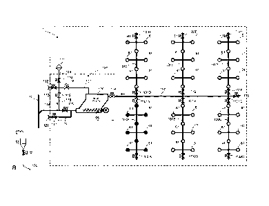
Figs. 1 - 6 present the operation of a subsystem 1 of a material conveying
system
according to the invention, in different operating phases. Fig. 7 presents the
total
system, which comprises five subsystems 1 (l, II, III, IV, V) and also a waste
station 2 and the necessary conveying piping 10, 11, 12, 114 between the
subsystems and the waste station.
Fig. 1 presents a subsystem 1, which comprises a material conveying pipe 100,
along the side of which at least one, typically many, input points 61 are
arranged.
An input point 61 is a feed-in station of material, more particularly of waste
material, intended to be conveyed, from which station the material, more
particularly waste material, such as household waste, intended to be conveyed
is
fed into the conveying system. The feed-in station can also be a refuse chute,
into
which material is fed from input apertures on different floors of a building.
The
system can comprise a number of feed-in stations 61, from which the material
intended to be conveyed is fed into conveying piping 100, 100A, 100B, 100C,
100D, 100E, 100F. A feed-in station 61 is marked in the figure with a dot, in
which
case by opening and closing a shut-off means, such as a valve means 60, in
connection with the feed-in station, material can be conveyed from an input
point
into the conveying pipe. Fig. la presents one input point 61 to be used in a
system
according to the invention and the discharge valve 60 of said input point in
more
detail. The input point is connected on the valve side to a conveying pipe
100.
Typically conveying piping comprises a main conveying pipe 100, to which it
has
been possible to connect a number of branch conveying pipes 100A, 100B, 1000,
100D, 100E, 100F and in turn to which branch conveying pipes it has been
possible to connect a number of feed-in stations 61. The embodiment of Fig. 1
comprises six branch conveying pipes 100A, 100B, 100C, 100D, 100F, 100E,
100F connected to a main conveying pipe 100. The material fed in is conveyed
along the conveying piping 100, 100A, 100B, 100C, 100D, 100E, 100F to the
accumulator tank 105 of the subsystem 1. The accumulator tank 105 can be
CA 02791755 2012-08-31
WO 2011/110740 PCT/F12011/050182
6
arranged in the waste space 120 of the subsystem 1, e.g. in a waste space
specific to a city block.
In the embodiment of the figure a pipe 107 is connected to the accumulator
tank
105, to the upper part of it, which pipe can be connected to a partial-vacuum
source. According to one embodiment the partial-vacuum source is a partial-
vacuum generator 25, 26 disposed at a waste station 2, the suction side of
which
partial-vacuum generator can be connected via piping 107, 118, 114, 10 to an
accumulator tank 105 and via it to conveying piping 100, 100A, 100B, 100C,
100D,
100E, 100F. Correspondingly, the lower part of the accumulator tank 105 can be
connected via piping 114 to the conveying piping 10. The pipe 114 comprises a
valve means 115 between the accumulator tank 105 and the pipe 118.
A subsystem 1 can, in addition, comprise means for arranging an own separate
partial vacuum source in connection with the subsystem. A medium pathway 107
to a first connection 113 is arranged from the accumulator tank 105, from the
upper part of the accumulator tank in Fig. 1. A second medium pathway 116 to a
second connection 121 is arranged from the lower part of the accumulator tank.
The second medium pathway 116 comprises a valve means 117 between the
accumulator tank 105 and the second connection 121. In the embodiment of the
figure the second medium pathway 116 leaves from the pipe 114 between the
accumulator tank 105 and the valve 115.
In a subsystem the action path of suction to the accumulator tank 105 can be
changed either to the upper part of the accumulator tank via the pathway 107
or to
the lower part of the accumulator tank via the pathway 114.
In the following the operation of the system is described by the aid of Figs.
1-6.
Fig. 1 shows a situation in which it is desired to empty one or more material
input
points of the branch conveying pipe 100A.
When the suction side of the partial-vacuum generator 25, 26 is connected
directly
or via a conveying air duct to the accumulator tank, to which the discharge
end of
a conveying pipe 100 is in turn connected, a partial vacuum is produced in the
conveying pipe 100. In this case the suction acts in the conveying pipe 100
via the
medium pathway 107 connecting to the accumulator tank. An area valve 101A is
between the main conveying pipe 100 and the branch conveying pipe 100A, which
CA 02791755 2012-08-31
WO 2011/110740 PCT/F12011/050182
7
valve is open in this operating phase. In this case the suction is able to act
also in
the branch conveying pipe 100A. In the case according to the figure, when the
valve means 60 of the point is opened in an input point 61, the material batch
intended to be conveyed transfers into the branch conveying pipe 100A and
onwards into the main conveying pipe 100. Possible replacement air into the
conveying pipe comes e.g. via the input point 61 when opening the valve 60 to
the
conveying pipe. When the valve 60 of an input point is closed, the line valve
102A
can be opened for receiving replacement air into the conveying pipe or the
line
valve 102A can be kept open when emptying material, in which case the material
of the feed-in container 61 to be emptied is dropped into the air current
moving in
the conveying pipe 100A.
The waste material is conveyed along the conveying piping 100A, 100 to the
accumulator tank 105, where the conveying air separates from the waste
material
and the waste material remains in the accumulator tank 105 (Fig. 2).
When all the input points intended to be emptied have been emptied and the
material is conveyed from the branch conveying pipe 100A into the conveying
pipe
100, the area valve 101A can be closed and the area valve 101B (Fig. 3) of the
branch conveying pipe 100B of the area intended to be emptied next can be
opened. After the input points of this branch conveying pipe have been emptied
into the conveying pipe 100B, 100 and conveyed in the piping onwards to the
accumulator tank 105 in a corresponding manner to that described above in
connection with Figs. 1 and 2, the area valve of the branch conveying pipe
101B is
closed and it is possible to move to the next area to be emptied by opening
e.g.
the area valve 101C (Fig. 4) of the branch conveying pipe 100C.
When the accumulator tank has filled up and it is desired to empty it onwards
(Fig.
5), either into the conveying pipe 10 or into another reservoir, e.g. into a
transport
tanker, the connection from the conveying pipe 100 of the subsystem to the
accumulator tank 105 is closed by closing the valve 104. Also the connection
from
the partial-vacuum generators 25, 26 to the medium pathway 107 to the upper
part
of the accumulator tank is closed with the valve means 119. The suction effect
is
transferred to the pathway 114 arranged in the lower part of the accumulator
tank,
in which case the material of the accumulator tank starts to move from the
accumulator tank via the pathway 114 into the conveying pipe 10. Replacement
air
is received in the accumulator tank 105, in the upper part of it, via the
replacement
CA 02791755 2012-08-31
WO 2011/110740 PCT/F12011/050182
8
air pipe 109 and the medium pathway 107, when the valves 108 and 110 are in
the open position.
The direction of conveyance of material and the direction of travel of air are
marked in the figures with arrows.
Conveyance of the material from the accumulator tank 105 can be assisted with
extractor devices 106, such as with a worm conveyor, which is driven with a
drive
device M.
Alternatively, material can be conveyed from the accumulator tank 105 via the
pipe
116 and the connection 121. In this case suction is achieved via the
connection
121 e.g. with a portable partial-vacuum generator (not shown). In the
operating
phase in question the valve 115 of the pathway 114 is closed, in which case
material is guided out via the connection 121.
It can also be conceived that the removal of material from the accumulator
tank
can be made more efficient by circulating conveying air via the connection 113
and
the pathway 107 into the upper part of the accumulator tank. In this case the
blowing side of the partial-vacuum generator would be connected to the pathway
107. Blowing together with suction could in this case assist and enhance the
conveyance of material from the accumulator tank into the conveying pipe.
A conveying air duct 22, 23, 24 leads from the separating device 20, 21 to the
means 25, 26 for forming a partial vacuum in the conveying pipe. In the
embodiment of Figs. 8a, 8b the means for forming a partial vacuum comprise two
vacuum pump units, both of which comprise a pump device 25; 26 and its drive
device M. By the aid of the means for forming a partial vacuum the partial
vacuum
needed in conveying material is produced in the conveying piping 100, 100A,
100B, 100C, 100D, 100E, 100F and/or in a part of it.
According to Fig. 8a the waste material to be conveyed is conveyed from the
subsystems 1 (I, II, III, IV, V,) of Fig. 7 along the piping 114, 10, 11
leading to the
waste station 2 to the separating device 20, in which the material being
conveyed
separates, e.g. due to the dropping of speed and due to centrifugal force,
from the
conveying air. The separated material is removed, e.g. according to need, from
the
separating device 20 to a material container, such as to a waste container 40,
or to
CA 02791755 2012-08-31
WO 2011/110740 PCT/F12011/050182
9
further treatment. There can be many separating devices 20, 21, as in Figs.
8a, 8b
two, a first separating device 20 and a second separating device 21, e.g. a
particle
separator.
The first separating device 20 is connected with the duct 22 to the second
separating device 21 and onwards with the conveying air duct 23, 24 to the
means
25, 26 for forming a partial vacuum in the conveying pipe. In the embodiment
of
the figure the means for forming a partial vacuum comprise a pump device 25,
26,
such as a vacuum pump unit. By the aid of the means for forming a partial
vacuum
the partial vacuum needed in conveying material is produced in the conveying
piping 10, 100 and/or in a part of it. The vacuum pump unit comprises at least
one
vacuum pump 25, 26, which is/are driven with a drive device M. The system
comprises means for circulating conveying air in a circuit, a part of which is
formed
by at least a part of the conveying piping 10.
The effect of the suction sides of the partial-vacuum generators of a waste
station
2 can be varied in the conveying pipe 10 according to Figs. 8a and 8b. In Fig.
8a
the pipe 11 is an inlet pipe of the conveying pipe 10, the valve 14 of which
pipe 11
is open to the pipe 19, which leads the pathway onwards to the separating
device
20. The blowing sides of the partial-vacuum pump devices can be connected to
blow into the conveying pipe, into the outlet pipe 12 of it. The first end 11
of the
conveying pipe 10, i.e. the inlet pipe in Fig. 8a, is connected via a
separating
means to the suction side of the pump devices, and the second end 12, the
outlet
side in Fig. 8a, is connected to the blowing side of the pump device, in which
case
there is a medium connection from the blowing side of the pump devices to the
second end 12 of the ring-shaped conveying pipe.
In the system presented by Fig. 7 the main conveying pipe 10 is ring-shaped,
in
which case the conveying air circulation in the main conveying pipe 10 can be
varied, depending on whether suction is arranged via the first end 11 or via
the
second end 12 of the main conveying pipe.
It is possible to effectively produce overpressure on the blowing side of a
pump
and/or a partial vacuum and/or a suction effect on the suction side of a pump
device.
CA 02791755 2012-08-31
WO 2011/110740 PCT/F12011/050182
The invention thus relates to a method in a pneumatic material conveying
system,
such as in a waste conveying system, which conveying system comprises at least
one input point 61 of material, more particularly of waste material, a
material
conveying pipe 100, which can be connected to an input point 61, and a
5 separating device, in which the material to be conveyed is separated from
the
conveying air, and also means for achieving a pressure difference in the
conveying pipe 100 at least during the conveyance of material. In the method
material is conveyed from an input point 61 to the accumulator tank 105 of a
subsystem 1, where the material is separated from the conveying air and in a
10 second phase the accumulator tank 105 of the subsystem is emptied.
According to one embodiment in the method in connection with a subsystem its
own partial-vacuum generating apparatus is used to achieve the suction effect
needed in material conveyance.
According to one embodiment in the method the partial-vacuum generating
apparatus of a more extensive waste conveying system is used to achieve the
suction effect needed in material conveyance.
According to one embodiment the material is conveyed from an accumulator tank
of a subsystem 1 onwards along a conveying pipe 10 to the separating device 20
of a waste station 2, where the material to be conveyed is separated from the
conveying air.
According to one embodiment the conveying pipe 10 of a more extensive system
is connected into a circuit such that conveying air can be circulated in the
conveying pipe 10.
According to one preferred embodiment in the method a partial vacuum is
achieved in the circuit with at least one pump device 25, 26, such as with a
partial-
vacuum generator and/or a fan, the suction side of which is connected to a
separating device 20.
According to one preferred embodiment in the method material is fed into the
conveying pipe 100 from the input points 61 of material, which are the input
points
of waste, such as waste receptacles or refuse chutes.
CA 02791755 2012-08-31
WO 2011/110740 PCT/F12011/050182
11
According to one embodiment in the method the subsystems 1 are waste
conveying systems of a certain area, such as of a city block.
According to one embodiment an extensive system, i.e. a total system, is a
waste
conveying system of a certain area, such as of a city district, which
extensive
system comprises a number of subsystems 1.
The invention also relates to an apparatus in a pneumatic material conveying
system, such as in a waste conveying system, which comprises at least one
input
point 61 of material, more particularly of waste material, a material
conveying pipe
100, which can be connected to an input point 61, and a separating device, in
which the material to be conveyed is separated from the conveying air, and
also
means 25, 26 for achieving a pressure difference in the conveying pipe 100 at
least during the conveyance of material. The apparatus comprises means for
conveying material from an input point 61 to the accumulator tank 105 of a
subsystem 1, where the material is separated from the conveying air and which
subsystem is fitted to be connected to a local partial-vacuum generating
apparatus
and to a partial-vacuum generating apparatus of a more extensive waste
conveying system.
According to one embodiment the apparatus comprises means for conveying
material from an accumulator tank of a subsystem 1 onwards along a conveying
pipe 10 to the separating device 20 of a waste station 2, where the material
to be
conveyed is separated from the conveying air.
According to one embodiment the conveying pipe 10 of a more extensive system
is fitted to be connected into a circuit such that conveying air can be
circulated in
the conveying pipe 10.
According to one embodiment at least one pump device 25, 26, such as a partial-
vacuum generator and/or a fan, the suction side of which is connected to a
separating device 20, is fitted into the circuit of a more extensive system.
According to one embodiment the input points 61 of material are the input
points of
waste, such as waste receptacles or refuse chutes.
CA 2791755 2017-05-16
,
12
-
According to one embodiment a subsystem 1 is a waste conveying system of a
certain area, such as of a city block.
According to one embodiment an extensive system, i.e. a total system, is a
waste
conveying system of a certain area, such as of a city district, which
extensive
system comprises a number of subsystems 1.
It is obvious to the person skilled in the art that the invention is not
limited to the
embodiments presented above, but that it can be varied within the scope of the
claims presented below. The characteristic features possibly presented in the
description in conjunction with other characteristic features can, if
necessary, also
be used separately to each other.