Note: Descriptions are shown in the official language in which they were submitted.
CA 02792231 2012-09-06
WO 2011/112595
PCT/US2011/027570
CONTROL ROD DRIVE MECHANISM FOR NUCLEAR REACTOR
BACKGROUND
[0001] In a pressurized water reactor (PWR) or other type of nuclear reactor,
movable control rods are used to control the nuclear reaction. The control
rods include a neutron absorbing material, and are arranged to be inserted
into the reactor core. In general, the further the control rods are inserted
into
the core, the more neutrons are absorbed and the more the nuclear reaction
rate is slowed. Precise control of the amount of insertion, and accurate
measurement of same, is useful in order to precisely control the reactivity.
The control rods drive mechanism (CRDM) provides this control.
[0002] In an emergency, the control rods can be fully inserted in order to
quickly quench the nuclear reaction. In such a "scram", it is useful to have
an
alternative fast mechanism for inserting the control rods. Additionally or
alternatively, it is known to have dedicated control rods that are either
fully
inserted (thus turning the nuclear reaction "off') or fully withdrawn (thus
making the reactor operational). In such systems, the "on/off" rods are
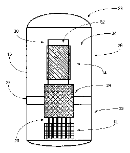
sometimes referred to as "shutdown rods" while the continuously adjustable
control rods are sometimes referred to as "gray rods".
[0003] Given these considerations, it is known to construct a CRDM
employing a lead screw that is engaged by a separable roller-nut assembly.
During normal operation, the roller-nut assembly is clamped onto the lead
screw by an affirmative magnetic force acting against biasing springs. By
turning the roller nut the lead screw, and hence the attached control rods,
are
moved in precisely controllable fashion toward or away from the reactor core.
In a scram, the electrical current is cut thus cutting the magnetic force, the
biasing springs open the separable roller nut, and the gray rod including the
lead screw scrams. An example of such a configuration is disclosed, for
example, in Domingo Ricardo Giorsefti, "Analysis of the Technological
Differences Between Stationary & Maritime Nuclear Power Plants", M.S.N.E.
1
Thesis, Massachusetts Institute of Technology (MIT) Department of Nuclear
Engineering (1977).
[0004] For an integral pressurized water reactor (integral PWR), it is known
to mount the CRDM externally and to couple with the control rods inside the
pressure vessel by suitable feedthroughs. To reduce the extent of
feedthroughs, it has also been proposed to integrate the CRDM within the
pressure vessel. See, for example, Ishizaka et al., "Development of a Built-In
Type Control Rod Drive Mechanism (CRDM) For Advanced Marine Reactor X
(MRX)", Proceedings of the International Conference on Design and Safety of
Advanced Nuclear Power Reactors (ANP '92), October 25-29, 1992 (Tokyo
Japan) published by the Atomic Energy Society of Japan in October 1992.
[0005] Existing CRDM designs have certain disadvantages. These
disadvantages are enhanced when an internal CRDM design is chosen in
which the complex electro-mechanical CDRM is internal to the high pressure
and high temperature environment within the pressure vessel. Placement of
the CRDM internally within the pressure vessel also imposes difficult
structural challenges.
[0006] The separable roller-nut creates a complex linkage with the lead
screw that can adversely impact gray rod insertion precision during normal
operation. Reattachment of the roller-nut to the lead screw can be complex,
and it may not be immediately apparent when contact is reestablished, thus
introducing a positional offset after recovery from the scram event.
Scramming the lead screw also has the potential to cause irrecoverable
damage to the threading or structural integrity of the lead screw. Still
further,
wear over time can be a problem for the complex separable roller-nut.
[0007] Another consideration is reliability. Because rod scramming is a
safety-critical feature, it must operate reliably, even in a loss of coolant
2
CA 2792231 2018-01-31
CA 02792231 2012-09-06
WO 2011/112595
PCT/US2011/027570
accident (LOCA) or other failure mode that may include interruption of
electrical power, large pressure changes, or so forth.
[0008] The control rod position detector is also typically a complex device.
In
some systems, an external position detector is employed, which requires
feedthroughs across the pressure vessel wall. For the internal CRDM of the
MRX reactor, a complex position detector was designed in which a transducer
generates a torsional strain pulse that passes through a magnetoresistive
waveguide, and magnetic field interactions are measured to adduce the rod
position. In general, an internal position detector operating on an electrical
resistance basis is prone to error due to temperature-induced changes in
material resistivity.
BRIEF SUMMARY
[0009] In one aspect of the disclosure, a control rod mechanism for use in a
nuclear reactor comprises: at least one control rod configured for insertion
in a
reactor core to absorb neutrons; a hollow lead screw; a motor operatively
coupled with the hollow lead screw to drive the hollow lead screw linearly
toward or away from the reactor core; a connecting rod connected with the
aforementioned at least one control rod and disposed partially inside the
hollow lead screw; a latch assembly having latches that when closed
operatively connect the connecting rod and the lead screw so that when the
latches are closed the connecting rod and the aforementioned at least one
control rod move together with the lead screw when the lead screw is driven
by the motor; and a release mechanism configured to cause the latches of the
latch assembly to open responsive to a scram condition to detach the
connecting rod from the lead screw such that the connecting rod and the
aforementioned at least one control rod scram but the lead screw remains
operatively coupled with the motor and does not scram.
[0010] In another aspect of the disclosure, a control rod drive mechanism
(CRDM) comprises: a lead screw; a motor threadedly coupled with the lead
3
CA 02792231 2012-09-06
WO 2011/112595
PCT/US2011/027570
screw to linearly drive the lead screw in an insertion direction or an
opposite
withdrawal direction; a latch assembly secured with the lead screw and
configured to (i) latch to a connecting rod and to (ii) unlatch from the
connecting rod, the connecting rod being free to move in the insertion
direction when unlatched; and a release mechanism configured to selectively
unlatch the latch assembly from the connecting rod.
[0011] In another aspect of the disclosure, a control rod drive mechanism
(CRDM) comprises: a plurality of CRDM units each comprising a lead screw
and a motor configured to drive the lead screw; and a support mounting the
plurality of CRDM units in a nuclear reactor vessel with the motors of
adjacent
CRDM units arranged at different heights respective to a reactor core of the
nuclear reactor vessel. Each CRDM unit is connected with one or more
control rods such that the motor driving the lead screw moves the connected
one or more control rods toward, away from, or within the reactor core.
100121 In another aspect of the disclosure, a control rod drive mechanism
(CRDM) comprises: a lead screw; a drive assembly configured to linearly
drive the lead screw in an insertion or opposite withdrawal direction, the
drive
assembly including a motor and at least one non-separable ball nut coupling
with the lead screw; and a latch assembly connected with the lead screw and
having (i) a latched state in which the latch assembly is latched to a
connecting rod and (ii) an unlatch state in which the latch assembly is not
latched to the connecting rod.
[0013] In another aspect of the disclosure, a control rod mechanism for use
in a nuclear reactor comprises: at least one control rod; a connecting rod
connected with the aforementioned at least one control rod at a lower end of
the connecting rod; and a control rod drive mechanism (CRDM) including a
latch assembly having (i) a latched state in which the latch assembly is
latched to an upper end of the connecting rod and (ii) an unlatched state in
which the latch assembly is not latched to the upper end of the connecting
4
CA 02792231 2012-09-06
WO 2011/112595
PCT/US2011/027570
rod, and a linear drive mechanism configured to drive the latch assembly
linearly toward or away from a nuclear reactor core.
[0014] In another aspect of the disclosure, in a control rod mechanism as set
forth in the immediately preceding paragraph the CRDM is configured to allow
the connecting rod to be removed by placing the latch assembly in the
unlatched state and drawing the connecting rod away from the nuclear reactor
core through the CRDIVI.
BRIEF DESCRIPTION OF THE DRAWINGS
[0015] The invention may take form in various components and
arrangements of components, and in various process operations and
arrangements of process operations. The drawings are only for purposes of
illustrating preferred embodiments and are not to be construed as limiting the
invention.
[0016] FIGURE 1 diagrammatically shows an illustrative nuclear reactor
vessel of the pressurized water reactor (PWR) type.
[0017] FIGURE 2 diagrammatically shows the upper internals section of the
illustrative nuclear reactor vessel of FIGURE 1.
[0018] FIGURES 3-5 diagrammatically show aspects of a shutdown control
rod system employing hydraulic lift.
[0019] FIGURES 6-15 diagrammatically show aspects of a control rod
system with electromagnetic gray rod functionality and a magnetic latch
system for scram functionality.
[0020] FIGURES 16-21 diagrammatically show aspects of a control rod
system with electromagnetic gray rod functionality and a latch system driven
by a hydraulic lift for scram functionality.
CA 02792231 2012-09-06
WO 2011/112595
PCT/US2011/027570
[0021] FIGURES 22 and 23 show perspective and perspective partial
sectional views, respectively, of a suitable array o S. f ("DWI empinying
staggered vertical motor arrangement.
[0022] FIGURES 24 and 25 show perspective and exploded perspective
views, respectively, of a "J"-groove coupling between the lower end of a
connecting rod and a rod cluster assembly.
DETAILED DESCRIPTION OF PREFERRED EMBODIMENTS
[0023] With reference to FIGURE 1, an illustrative nuclear reactor vessel of
the pressurized water reactor (PWR) type is diagrammatically depicted. An
illustrated primary vessel 10 contains a reactor core 12, internal helical
steam
generators 14, and internal control rods 20. The illustrative reactor vessel
includes four major components, namely: 1) a lower vessel 22, 2) upper
internals 24, 3) an upper vessel 26 and 4) an upper vessel head 28. A
mid-flange 29 is disposed between the lower and upper vessel sections 22,
26. Other vessel configurations are also contemplated. Note that FIGURE 1 is
diagrammatic and does not include details such as pressure vessel
penetrations for flow of secondary coolant into and out of the steam
generators, electrical penetrations for electrical components, and so forth.
[0024] The lower vessel 22 of the illustrative reactor vessel 10 of FIGURE 1
contains the reactor core 12, which can have substantially any suitable
configuration_ One suitable configuration includes a stainless steel core
former structure that contains the fuel assemblies and is replaceable in order
to refuel the reactor, and which is supported by the lower vessel. The
illustrative upper vessel 26 houses the steam generators 14 for this
illustrative
PWR which has an internal steam generator design (sometimes referred to as
an integral PWR design). In FIGURE 1, the steam generator 14 is
diagrammatically shown. A cylindrical inner shell or upper flow shroud 30
separates a central riser region 32 from an annular downcomer region 34 in
which the helical steam generators 14 are located. The illustrative steam
6
CA 02792231 2012-09-06
WO 2011/112595
PCT/US2011/027570
generator 14 is a helical coil design, although other designs are
contemplated.
Primary reactor coolant flows across the outside of tubes of the steam
generator 14 and secondary coolant flows inside the tubes of the steam
generator 14. In a typical circulation pattern the primary coolant is heated
by
the reactor core 12 and rises through the central riser region 32 to exit the
top
of the shroud 30 whereupon the primary coolant flows back down via the
downcomer region 34 and across the steam generators 14. Such primary
coolant flow may be driven by natural convection, by internal or external
primary coolant pumps (not illustrated), or by a combination of pump-assisted
natural convection. Although an integral PVVR design is illustrated, it is
also
contemplated for the reactor vessel to have an external steam generator (not
illustrated), in which case pressure vessel penetrations allow for transfer of
primary coolant to and from the external steam generator. The illustrative
upper vessel head 28 is a separate component. It is also contemplated for the
vessel head to be integral with the upper vessel 26, in which case the steam
generator 14 and upper shroud 30 are optionally supported by lugs on the
inside of the vessel head.
[0025] The illustrative embodiment is an integral PWR in that it includes the
internal steam generators 14, which in general may have various geometric
configurations such as helical, vertical, slanted, or so forth. For the
purpose of
redundancy, it is generally advantageous to have more than one steam
generator, whose pipes or tubes are typically interleaved within the
downcomer region 34 to facilitate thermal uniformity; however, it is
contemplated to include only a single steam generator. Although the
illustrative steam generators 14 are shown disposed or wrapped proximate to
the shroud 30, in general the steam generators may fill a substantial volume
of the downcomer region 34, and in some embodiments the steam generators
may substantially fill the annular volume between the outer surface of the
shroud 30 and the inside surface of the pressure vessel 10. It is also
contemplated for the internal steam generators or portions thereof to be
disposed in whole or in part in the riser region 32,above the shroud 30, or
7
CA 02792231 2012-09-06
WO 2011/112595
PCT/US2011/027570
elsewhere within the pressure vessel 10. On the other hand, in some
embodiments the PWR may not be an integral PWR, that is, in some
embodiments the illustrated internal steam generators may be omitted in favor
of one or more external steam generators. Still further, the illustrative PWR
is
an example, and in other embodiments a boiling water reactor (BWR) or other
reactor design may be employed, with either internal or external steam
generators.
[0026] With reference to FIGURE 2, the upper internals section 24 in greater
detail. In the illustrative design the upper internals section 24 provides
support
for control rod drives or drive mechanisms 40, 42 and control rod guide
frames 44 and is also the structure through which control rod drive power and
control instrumentation signals pass. This allows the upper vessel 26 and
integral steam generator 14 to be removed independently of the control rod
drives and associated structure. However, a more integrated design is also
contemplated, such as using a common section for both the CRDM support
and the integral steam generator support.
[0027] With particular reference to the illustrative embodiment of FIGURE 2,
the upper internals structure 24 includes an upper internals basket 46, a
CRDM support structure 48, control rod guide frames 44, and the control rod
drive mechanisms 40, 42 themselves. The upper internals basket 46 is
suitably a welded structure that includes the mid-flange 29 and the support
structure for the control rod guide frames 44. In one suitable embodiment, the
control rod guide frames 44 are separate 3041. stainless steel =welded
structures that are bolted in place, the mid-flange 29 is a SA508 Gr 4N CI 2
carbon steel forging, and the balance of the structure is 304L stainless
steel.
The CRDM support structure 48 includes support lattices for the control rod
drives 40, 42 and guide structure for the in-core instruments. All of these
are
suitably 304L stainless steel. The CREW support structure 48 is bolted to the
upper internals basket 46. These are merely illustrative materials and
construction, and other configurations and/or reactor-compatible materials are
also contemplated.
8
CA 02792231 2012-09-06
WO 2011/112595
PCT/US2011/027570
[0028] The illustrative example of FIGURE 2 employs two types of control
rod drives 40, 42: a hiydraulic control rOd drive type 42 thiat operates the
shutdown rods which are either fully withdrawn or fully inserted into the
core;
and an electrical control rod drive type 40 that operates the gray rods which
are inserted various amounts throughout the life of the core to control the
nuclear reaction rate during normal reactor operation. The gray rods are also
configured to scram, that is, to be rapidly inserted into the reactor core 12,
during certain emergency conditions. In other embodiments, it is
contemplated to omit the shutdown rods entirely in which case the gray rods
also provide shutdown operation.
[0029] With continuing reference to FIGURE 2 and with further reference to
FIGURES 3-5, aspects of the shutdown rods are illustrated. The shutdown
rods are suitably arranged in clusters mounted on spiders or the like that are
all operated in single bank and are all moved by a single shutdown rod drive
42. FIGURES 3-5 show only the single shutdown rod drive 42, but not the
spiders and individual shutdown rods. This configuration is cognizant of the
fact that the shutdown rods are used in a binary "on/off" manner, and are
either all wholly inserted into the reactor core 12 in order to shut down the
reaction, or are all wholly withdrawn from the reactor core 12 in order to
allow
normal reactor operation.
[0030] With particular reference to FIGURE 3, the shutdown rod drive 42
includes a cylinder housing 50, a cylinder cap 52, a cylinder base plate 54,
and a connecting rod 56 providing connection to the shutdown rod lattice (not
shown). The illustrative shutdown rod drive 42 of FIGURES 3-5 is a
hydraulically actuated drive using reactor coolant inventory clean-up return
fluid from high pressure injection pumps at approximately 500 F (260 C) and
1600 psi to hold the shutdown rod bank out of the reactor core 12.
[0031] With particular reference to FIGURE 4, a sectional view of the piston
region with the rod in the withdrawn position is shown. In an enlarged portion
of FIGURE 4 a vent port 60 of the cylinder cap 52 is shown, together with a
lift
9
CA 02792231 2012-09-06
WO 2011/112595
PCT/US2011/027570
piston 62, piston rings 64 (which in some embodiments are metallic), a scram
buffer 66, and a buffer cocking spring 68. The withdrawn position shown in
FIGURE 4 corresponds to the shutdown control drive cylinder 42 being
pressurized.
[0032] With particular reference to FIGURE 5, a sectional view of the piston
region with the rod in the inserted position is shown. An enlarged portion of
FIGURE 5 shows the lift piston 62, the piston rings 64, the scram buffer or
scram buffer piston 66, a rod guide bushing 70, and rod sealing rings 72
(which in some embodiments are metallic). The cylinder base plate 64 is seen
in the enlarged portion to include a pressure port or inlet port 74. The
inserted
position shown in FIGURE 5 corresponds to the shutdown control drive
cylinder 42 being unpressurized.
[0033] In some embodiments, the coolant is allowed to bleed past the piston
and shaft seals 64, 72 and becomes part of the inventory returned to the
reactor vessel 10. The shutdown rod drive cylinder 42 is mounted above the
reactor core 12. A hydraulic line (not shown) to actuate the cylinder 42 is
routed through the flange 29 and instrument lines are routed through pressure
tight conduit to common connectors that are also optionally used for the gray
rod drives 40. The extension rods that connect the control rod spiders to the
shutdown rod lattice are optionally designed so that they will slide through
the
lattice so that a single stuck cluster will not prevent the other sets of
control
rods from dropping. Additionally, the extension rods are designed to be
disengaged from the control rod spider so that the shutdown rods remain in
the core when the upper internals 24 are removed. Disengagement and
reengagement is done using remote tooling at during refueling operations.
[0034] During normal reactor operation, the shutdown rods are suspended
completely out of the reactor core (that is, in the withdrawn position) by
pressurization of the shutdown rod hydraulic cylinder 42. For example, in one
suitable embodiment coolant inventory clean-up return fluid from the high
pressure injection pumps is supplied at 500 F (260 C) and 1600 psi to the
CA 02792231 2012-09-06
WO 2011/112595
PCT/US2011/027570
underside of the lift cylinder piston 62, via the inlet port 74 of the
cylinder base
54. In this example, the fluid present in the cylinder 50 above the piston 62
is
supplied from the reactor vessel 10 through the cylinder cap vent port 60, and
is therefore at the reactor vessel conditions of 600 F (315 C) and 1500 psi,
resulting in a net 100 psi pressure differential across the piston 62. Piston
sizing is selected such that the developed pressure differential is sufficient
to
support the specified load of the shutdown rods and supporting spiders and
other associated components and lift the shutdown rod bank through the
cylinder stroke to the top stop of the piston 62.
[0035] In the event of a vessel-pressurized scram, the shutdown rod bank is
abruptly released by ceasing the supply of pressurized coolant to the bottom
side of the lift piston 62 and venting the supply line to atmospheric
pressure.
In the aforementioned example the vessel pressure at the top surface of the
lift piston 62 is expected to create an initial 1500 psig pressure
differential
across the lift piston, which acts along with the influence of gravity to
propel
the translating assembiy (including the lift piston 62, scram buffer piston
66,
cocking spring 68, connecting rod 66, and shutdown rod lattice (not shown)
downward toward the full insertion position illustrated in FIGURE 5. During
the
descent of the translating assembly, the force of the buffer cocking spring 68
holds the buffer piston 66 out of the bore of the lift piston 62, preserving a
fluid-filled buffer cavity between the two pistons 62, 66. When the bottom
surface of the buffer piston 66 impacts the fixed base plate 54 of the
cylinder
assembly, the continued travel of the lift piston 62 expels the trapped fluid
through controlled flow restrictions, thereby dissipating the kinetic energy
of
the translating assembly. Additionally, kinetic energy is dissipated through
elastic deformation of the translating assembly components, especially the
long, relatively slender, connecting rod 56. Other kinetic energy dissipation
mechanisms are also contemplated. When the fluid is expelled from the
cavity, the lift piston 62 impacts the buffer piston 66, bringing the
translating
assembly to rest.
11
CA 02792231 2012-09-06
W02011/112595
PCT/US2011/027570
[0036] With continuing reference to FIGURES 1 and 2 and with further
reference to FIGURES 6-14, an illustrative embodiment of the gray rods and
associated drive mechanisms 40 is described. As seen in FIGURE 6, in the
illustrative embodiment there are two different gray rod configurations (Type
1
and Type 2). The gray rods 80 are arranged as gray rod clusters, which in
turn are yoked together in groups of two or four and supported by connecting
rods 82 as shown in FIGURE 6. The configuration Type 1 also includes a
counterweight 84 in place of one connecting rod/cluster unit. More
particularly,
a yoke 86 connects two connecting rods 82 and the counterweight 84 to form
a configuration of Type 1. A yoke 88 connects three connecting rods 84 to
form a configuration of Type 2. The gray rod drives 40 are mounted above the
reactor core 12. FIGURE 7 shows a plan view of the locations of the gray rod
drives 40 and of the shutdown rods lift cylinder 60, respective to the CREW
support structure 48. The shutdown rods lift cylinder 60 is centrally located.
Four outboard gray rod drives 40, each moving two rod configurations of Type
1 including yokes 86, move simultaneously. Two inboard drives 40, each
moving four rod configurations of Type 2 including yokes 88, move
simultaneously. These different sets of drives 40 optionally move together or
independently. Power and signal connections are suitably routed through a
pressure tight conduit or in-core instrumentation guide 90 to connectors on
the mid-flange 29 (not shown in FIGURE 7).
[00371 As with the shutdown rods, the extension rods that connect the
control rod spiders to the rod lattice are optionally designed so that they
will
slide through the lattice so that a single stuck cluster will not prevent the
other
sets of control rods from dropping. Additionally, the extension rods are
optionally designed to be disengaged from the control rod spider so that the
gray rods can remain in the core when the upper internals are removed or be
removed while the upper internals are on their support stand. Two suitable
design styles for the gray rod control mechanism include the "magnetic jack"
type and the "power screw" type. Of these, the power screw type is expected
to provide more precise position control for the gray rod clusters, and
12
CA 02792231 2012-09-06
WO 2011/112595
PCT/US2011/027570
accordingly the illustrated embodiment employs the power screw type control
mechanism.
[00381 With reference to FIGURE 8, in one illustrated embodiment the gray
rod control mechanism 40 employs a ball nut lifting rod configuration. FIGURE
8 shows both the fully inserted state (left-side drawing) and fully withdrawn
state (right-side drawing). The drawings of FIGURE 8 show the yoke 88 of the
Type 2 configuration; for the Type 1 arrangement the yoke 88 is replaced by
the yoke 86. In the embodiment shown in FIGURE 8, a bottom stop/buffer
assembly 100 is mounted on a reactor support 101, optionally with additional
lateral support provided for the electromagnet coil assembly. Lower and upper
support tubes 102, 104, which mount to the top of the bottom stop 100,
provide the guidance for the lead screw/torque taker assembly. A ball
nut/motor assembly 106 mounts on top of the upper support tube 104 and an
electromagnet coil assembly 108 mounts to the top of the motor. Within the
electromagnet coil assembly 108 resides a lifting rod-to-lead screw latching
assembly 110 that (when latched) supports a lifting/connection rod assembly
112 (seen extended in the inserted state, i.e. left-side drawing).
[0039] A position indicator assembly is mounted to the support tubes 102,
104 between the ball nut/motor assembly 106 and the bottom stop assembly
100. In some embodiments, the position indicator is a string potentiometer
suitably mounted below the latching assembly 110, although other mounting
locations are contemplated. The illustrated string potentiometer includes a
tensioned spool 120 mounted on the support tube 102 and a "string" or cable
or the like 122 having an end attached to the lifting/connection rod assembly
112 such that the string or cable 122 is drawn off the spool 120 against the
tension as the lifting/connection rod assembly 112 (and, hence the attached
gray rod clusters) move toward the reactor core 12 (not shown in FIGURE 8).
When the motion is reversed, the tension in the tensioned spool 120 causes
the string or cable 122 to roll back onto the spool 120. A rotational sensor
124
measures the rotation of the tensioned spool 120 using an encoder that
counts passage of fiducial markers or another rotational metric. The mounting
13
CA 02792231 2012-09-06
WO 2011/112595
PCT/US2011/027570
of the string potentiometer can be otherwise than that illustrated, so long as
the tensioned spool 120 is mounted at a location that does not move with the
gray rods and the string or cable 122 is secured to move with the gray rods.
It
is also contemplated to integrate the rotational sensor 124 with the tensioned
spool 120. The string potentiometer provides an electrical output signal
consistent with the location of the connecting rod or other component 112 that
moves with the gray control rod, thus providing positional information for the
gray control rods within the reactor core 12. The electrical position
indication
signal is conveyed out of the reactor vessel 10 through an electrical
feedthrough (not shown), which can be made small and/or integrated with
other electrical feedthroughs. The position indicator device is configured and
calibrated for operation at reactor vessel temperature and radiation level.
[0040] With continuing reference to FIGURE 8 and with further reference to
FIGURES 9-14, in the illustrated embodiment the translating assembly of the
gray rod CRDM 40 includes three elements: a lead screw/torque taker
assembly; a lifting rod/connecting rod assembly; and a latching system that
operatively connects the lifting rod with the lead screw. FIGURE 9 shows the
lead screw/torque taker assembly in perspective (left side) and sectional
(right
side) views. A motor assembly includes a stator housing 130 housing a stator
132 and a rotor 134. An upper stator end plate 136 and a radial bearing 138
with adjustable spacer 140 complete an upper portion of the motor assembly,
while a lower housing 142 and a thrust bearing 144 complete a lower portion
of the motor assembly. A lower ball-nut assembly 150 disposed within the
lower housing 142 is threaded to the rotor 134, and an upper ball nut
assembly 152 is also threaded to the rotor 134. Both ball-nut assemblies 150,
152 are coupled in threaded fashion with a lead screw 160 (shown in part in
FIGURE 9). FIGURE 9 further shows portions of the lifting rod 112 and the
upper support tube 104.
[0041] With reference to FIGURE 10, the latching system is illustrated,
including the lifting rod-to-lead screw latching assembly 110 and a portion of
the electromagnet coil assembly 108. Also shown in FIGURE 10 are an end
14
CA 02792231 2012-09-06
WO 2011/112595 PCT/US2011/027570
ill of the lifting rod 112 and a proximate end of the lead screw 160
terminating at or in the latching assembly 110. Latches 170 directly connect
the top end 111 of the lifting rod 112 to the lead screw 160 for normal
operation, and disconnect the lifting rod 112 during scram (see FIGURE 11).
The bottom of the lifting rod 112 is threaded to the top of the connecting rod
82 (optionally by the intermediary yoke 86 or intermediary yoke 88) thereby
creating a continuous lifting rod/connecting rod assembly. The bottom of the
connecting rod 82 couples directly to the control rod spiders thereby
attaching
the control rods to the mechanism. Optionally, a magnet 113 is disposed
proximate to the top 111 of the lifting rod 112 to provide a magnetic signal
for
a magnetically-based position indicator (see FIGURE 21). FIGURE 10 also
shows a portion of the motor including portions of the motor housing 130,
stator 132, and rotor 134, which is shown in full in FIGURE 9.
[0042] The latches 170 are housed in a latch housing 172 that includes a
spring guide for a latch spring 174. Additional components of the illustrated
latching system embodiment include an electromagnet housing 176 housing
= = electromagnets 177 forming an electromagnet coil stack, and
permanent
=
magnets 178 on the latches 170. The lead screw 160 is threaded into a
latching system base 179 of the latch housing 172. The latches 170 are
arranged to pivot about pivot locations 180 to provide a failsafe scram due to
downward rod load.
e[0b04e131]n ultnmtheitse re emsbsoedmi embodiment ethset sleeaedn sincrFeiwG
FIGURE
is9)cwonntiicnnuoeul i es lwy ssfueprpvoertreydfi nbey
= control of lead screw position =and consequently very fine control of the
position of the control rod assembly. In the illustrated embodiment, the motor
(e.g., stator 132, rotor 134) is a synchronous motor in which the rotor 134 is
a =
permanent magnet. This design has advantages such as compactness and
simplicity; however, other motor configurations are also contemplated.
[0044] The lead screw 160 does not scram. Instead, during a scram the top
end of the lifting rod 112 of the lifting rod/connection rod assembly is
=
CA 02792231 2012-09-06
WO 2011/112595
PCT/US2011/027570
'disconnected from the lead screw 160 by the magnetically activated latching
system (see FIGURE 11). When power is cut to the electromagnets 177 the
failsafe latching system releases the lifting/connection rod assembly (and
thus
the control rod assembly) from the lead screw 160 thereby initiating a scram.
A bottom stop and buffering system (not illustrated, but suitably similar to
the
bottom stop and buffering system of the illustrative shutdown rods described
herein with reference to FIGURES 4 and 5) is incorporated into the
base/buffer assembly to dissipate the kinetic energy at the end of the scram
stroke and to set the rod bottom elevation. A torque taker (not shown) is
attached to the lead screw 160 to react the motor torque thereby providing
translation of the lead screw/control rod assembly.
[00451 The normal state, that is, the state prior to scram, is shown in
FIGURES 9 and 10. FIGURE 9 illustrates the ball nut motor assembly and
FIGURE 10 shows the latching system engaged for normal operation. As
seen in FIGURE 10, the permanent magnets 178 on the latches 170 are
magnetically attracted toward the powered electromagnets 177 thus pivoting
the latches 170 about the pivot locations 180 and engaging the latches 170
with a mating region of the lifting rod 112. Thus, the latches 170 are secured
with the lifting rod 112 in the normal state shown in FIGURE 10. Further, the
latching system base 179 is threaded to or otherwise secured with the lead
screw 160. Accordingly, in the normal state of FIGURE 10 the lifting rod 112
is
secured with the lead screw 160 via the latching system, and so as the ball
nut motor assembly shown in FIGURE 9 translates the lead screw 160 the
lifting rod 112 is translated with the lead screw 160.
[00461 Scram is described with reference to FIGURE 11, which shows the
lifting rod 112, and consequently the control rod assembly, during a scram. To
initiate scram the power to the electromagnets 177 is cut, that is, turned
off.
This removes the attractive force on the permanent magnets 178 on the
latches 170, and the latch spring 174 extends to pivot the latches 170 about
the pivot locations 180 and away from the mating region of the lifting rod
112.
This disengages the latches 170 from the lifting rod 112, and the
16
CA 02792231 2012-09-06
WO 2011/112595
PCT/US2011/027570
lifting/connection rod assembly (and thus the control rod assembly) falls
toward the reactor 12. The lead screw 160 is seen in FIGURE 11 still at the
previous withdrawal height (that is, the lead screw 160 is not scrammed), but
power to the electromagnet coils 177 has been cut so that the magnetic field
from the coils is removed.
(00471 As further shown in FIGURE 11, the pivoting of the latches 170 about
the pivot locations 180 is stopped by impingement at a location 181 with the
spring guide of the latch housing 172.
10048] With continuing reference to FIGURE 11 and further reference to
FIGURES 12 and 13, to re-engage the mechanism after a scram, the lead
screw 160 is driven to the fully inserted position via the ball nut motor (see
again FIGURE 9). A lead screw on-bottom sensor is used to confirm lead
screw full insertion. With particular reference to FIGURE 12, as the lead
screw
160 nears the fully inserted position an angled camming surface 182 on the
top 111 of the lifting rod 112, which is scrammed to the bottom, will cam the
latches 170 to their near full out position. With particular reference to
FIGURE
13, when power is restored to the electromagnets 177, the latches 170 will
fully re-engage with the mating region of the lifting rod 112 so that the
lifting/connection rod assembly is once again connected to the lead screw
160. Normal operation can then resume as per FIGURE 10. To reiterate,
FIGURE 12 shows the lead screw 160 being driven back down to the fully
inserted position in preparation for re-engagement of the lifting rod 112.
Power to the electromagnet coils 177 is still cut and the latches 160 are
still
disengaged. The angled camming surfaces 182 on the top 111 of the lifting
rod 112 are camming the latches 170 back into partial engagement with the
top 111 of the lifting rod 112. FIGURE 13 shows the lead screw 160 still on
bottom but with the power restored to the electromagnet coils 177. The
restored magnet field has now re-engaged the latches 170 with the mating
region of the lifting rod 112.
17
CA 02792231 2012-09-06
W02011/112595
PCT/US2011/027570
[00491 FIGURE 9 diagrammatically shows a suitable embodiment of the ball
nut/motor assembly 106, including lower and upper ball nut assemblies 150,
152. In general, substantially any type of motor can be used, suitably
configured for operation in the pressure vessel environment.
[00501 With reference to FIGURES 14 and 15, an illustrative embodiment is
shown which employs a brushless DC electronically controlled (BLDG) motor
184 with lower ball nut assembly 185. The assembly 184, 185 is an illustrative
embodiment of the ball nut/motor assembly 106. With particular reference to
FIGURE 14, the illustrative BLOC motor 184 includes a wound stator core
assembly 186 disposed between a stator outer shell 187 and a stator inner
shell 188 and secured by a stator upper housing 189 and stator lower housing
190. A permanent magnet rotor 191 includes permanent magnets 192. The
BLDG motor 184 produces torque from interaction of magnetic flux of the rotor
magnets 192 and the current carrying stator conductors of the stator core
assembly 186. The lower ball nut assembly 185 is analogous to the lower
ball-nut assembly 150 of FIGURE 9; however, in the illustrative assembly of
FIGURE 14 there is no upper ball-nut assembly corresponding to the upper
ball nut assembly 152 of FIGURE 9. The assembly of FIGURE 14 also
includes a radial bearing 193, a thrust bearing 194 secured by a thrust
bearing lock nut 195, =and a motor top cap 196. An insulated and
environmentally robust electrical connection to the motor is provided by a
lead
wire gland 197. For example, some suitable insulated lead wire glands are
available from Conaxl) Technologies (Buffalo, New York, USA). With
particular reference to FIGURE 15, the BLDC motor 184 arid lower ball-nut
assembly 185 are illustrated in the context of the control rod drive mechanism
(CRDM) of FIGURES 10-13. The illustrative CRDM of FIGURE 15 also
includes the previously described electromagnet coil stack assembly 177,
lifting rod-to-lead screw latching assembly 110, lead screw 160, and lifting
rod
112. The ball-nut assembly 185 engages the lead screw 160 so that, as the
motor 184 rotates the permanent magnet rotor 191 and the secured ball-nut
assembly 185, the lead screw 160 is driven linearly.
18
CA 02792231 2012-09-06
WO 2011/112595
PCT/US2011/027570
[0051] With returning reference to FIGURES 1 and 2, an advantage of the
disclosed reactor design is that the middle section includes the internals
support flange or ''mid-flange" 29. This section can be made relatively thin,
and provides support for the control rod drive mechanism and guides for the
in-core instrumentation. This section provides electrical and hydraulic inputs
for the control rod drive mechanisms (CRDMs). A reactor coolant drain
penetration (not illustrated) is optionally also incorporated in this section.
This
drain line, if incorporated, is optionally isolated by an internal valve
whenever
the reactor is pressurized to limit or eliminate its potential as a loss of
coolant
accident (LOCA) site,
[0052] The illustrated upper internals 24 including the CRDM do not include
illustrated thermal insulation. However, it is contemplated to insulate these
components using an insulation system capable of withstanding a design
temperature of at least about 650 F (343 C), By using the insulation system,
external cooling water will not be required although may optionally also be
used. For example, cooling water can be supplied to the electrical devices to
reduce the severity of the heat duty imposed by the operating environment.
The insulation system facilitates locating the electrical CRDM within the
pressure vessel, which reduces the overall height of the reactor vessel 10,
significantly reduces the number of penetrations into the reactor vessel 10,
and enables a complete reactor module to be shipped as a single unit.
Another advantage is reduction of the overall height of the containment
structure (not shown). Although the use of insulation is believed to be
advantageous, other contemplated solutions include the use of water cooling
and/or selecting materials capable of withstanding the high operating
temperature without insulation.
[0053] The illustrative reactor embodiment is an integral pressurized water
reactor (PWR) configuration. However, one or more of the disclosed
techniques, apparatuses, or so forth are also expected to be suitably used in
other types of nuclear reactor vessels, such as boiling water reactors (BVVRs)
19
CA 02792231 2012-09-06
WO 2011/112595
PCT/US2011/027570
that can advantageously incorporate internal CRDM assemblies, efficient
control rod position sensors, and so forth.
[0054] The CORM configuration of FIGURES 2-15 provides two separate
scram mechanisms: a hydraulic scram provided by the shutdown rods
described with reference to FIGURES 3-5; and a magnetic latch scram
mechanism described with reference to FIGURES 6-15 with the magnetic
latch system described with particular reference to FIGURES 10-15. This
advantageously provides redundant hydraulic and magnetic scram
mechanisms thus reducing likelihood of a complete scram failure in the event
of a loss of coolant accident (LOCA) or other safety-related event.
[0055] With reference to FIGURES 16-20, in another control rod system
embodiment is described, which provides electromagnetic gray rod
functionality and a hydraulic latch system providing scram functionality. Like
the control rod system of FIGURES 6-15, the control rod system of FIGURES
16-20 allows for failsafe scram of the control rod cluster without scramming
the lead screw.
[0056] With particular reference to FIGURE 16, the motor/ball nut assembly
of FIGURE 15 is employed, such that a lead screw 200 is permanently
engaged to the ball-nut assembly 185 which provides for axial translation of
the lead screw 200 by driving the motor 184. A control rod cluster (not shown
in FIGURE 16) is connected to the lead screw 200 via a connecting rod or
connecting rod assembly 204 and a latch assembly 206. The lead screw 200
is substantially hollow, and the connecting rod assembly 204 fits coaxially
inside the inner diameter of the lead screw 200 and is free to translate
vertically within the lead screw 200. The latch assembly 206, with two spring
loaded latches, is permanently attached to the top of the lead screw 200.
When the latches are engaged with the connecting rod 204 they couple the
connecting rod 204 to the lead screw 200 and when the latches are
disengaged they release the connecting rod 204 from the lead screw. In the
illustrated embodiment, latch engagements and disengagements are
CA 02792231 2012-09-06
WO 2011/112595 PCT/US2011/027570
achieved by using a four-bar linkage cam system including two cam bars 208
and at least two (and, in the illustrated embodiment four) cam bar links 209
per cam bar 208. The additional cam bar links add support for the cam bar.
When the cam bars 208 move upward the cam bar links 209 of the four-bar
linkage also cams the cam bars 208 inward so as to cause the latches to
rotate into engagement with the connecting rod 204. In the illustrated
embodiment, a hydraulic lift assembly 210 is used to raise the cam bar
assemblies 208. In an alternative embodiment (not illustrated), an electric
solenoid lift system is used to raise the cam bar assemblies. When a lift
force
is applied to the cam system, the upward and inwardly-cammed motion of the
cam bars 208 rotates the latches into engagement thereby coupling the
connecting rod 204 to the lead screw 200. This causes the control rod cluster
to follow lead screw motion. When the lift force is removed, the cam bars 208
swing down and are Gemmed outward by the cam bar links 209 of the four-bar
linkage allowing the latches to rotate out of engagement with the connecting
rod 204. This de-couples the connecting rod 204 from the lead screw 200
which causes the control rod cluster to scram. During a scram, the lead
screw 200 remains at its current hold position. After the scram event, the
lead
screw 200 is driven to the bottom of its stroke via the electric motor 202.
When the lift force is reapplied to the cam system via the hydraulic lift
assembly 210, the latches are re-engaged and the connecting rod is re-
coupled to the lead screw 200, and normal operation can resume. Still further,
other latch drive modalities are contemplated, such as a pneumatic latch drive
in which pneumatic pressure replaces hydraulic pressure in the illustrated
lift
assembly 210.
[0057] With continuing reference to FIGURE 16, the lead screw 200 is
arbitrarily depicted in a partially withdrawn position for illustration
purposes. It
=
can be seen in FIGURE 16 that the latching assembly 206 is attached to the
top of the lead screw 200. In FIGURE 16 the latches are engaged the
= connecting rod 204, which is coupled to the lead screw, is also at the
same
partially withdrawn position as the lead screw 200. The ball nut 186 and motor
21
CA 02792231 2012-09-06
WO 2011/112595 PCT/US2011/027570
184 are at the bottom of the control rod drive mechanism (CDRM), the latch
cam bars 208 extend for the full length of mechanism stroke, and the
hydraulic lift system 210 is located at the top of the mechanism. In some
embodiments, the CREW of FIGURES 16-20 is an integral CDRM in which
the entire mechanism, including the electric motor 184 and ball nut 185, the
latching system 206, and a position indicator (not shown in FIGURE 16), are
located within the reactor pressure vessel 10 at full operating temperature
and
pressure conditions.
1[0058] With reference to FIGURES 17 and 18, the lower end of the control
rod drive mechanism (CRDM) including the latching assembly 206 is
illustrated in additional detail. The latching assembly 206 includes a latch
housing 212 and latches 214. The latch housing 212 provides a frame or
support for pivot positions 216 (e.g.. pivot pins or rods) about which the
latches 214 can pivot. In FIGURE 16, the connecting rod 204 is withdrawn,
that is, latches 214 of the latching assembly 206 are pivoted inwardly into
engagement with mating region at an upper end215 of the connecting rod
204. In the illustrative embodiment, the top of the connecting rod 204
includes
== the optional magnet 113 to provide a magnetic signal for a
magnetically-based position indicator (see FIGURE 21). FIGURE 17 shows
the connecting rod 204 scrammed, that is, latches 214 are pivoted outwardly
so as to be disengaged from the mating region at the upper end 215 of the
connecting rod 204 so that the connecting rod 204 is mechanically decoupled
from the lead screw 200 and is free to move within the inner diameter of the
lead screw 200. Thus decoupled as shown in FIGURE 17, the connecting rod
204 (and hence the control rod bundle or bundles secured to the connecting
rod 204) fall toward the reactor core 12 under the influence of gravity. In
both
FIGURES 16 and 17, the lead screw 200 is again shown slightly withdrawn to
an arbitrarily position ¨as seen in FIGURE 17 the lead screw 200 does not
scram.
[0059] Referring particularly to FIGURE 17, the two cam bars 208 are shown
raised at their maximum inward (that is, engaged) position. The inward
22
CA 02792231 2012-09-06
WO 2011/112595
PCT/US2011/027570
movement of the cam bars 208 caused by the can bar links 209 rotates or
pivots the latches 214 inward into full engagement with the mating region at
the upper end 215 of the connecting rod 204. When moved inward to full
engagement, the cam bars 208 are supported along their full length by a cam
bar housing cover 222 which provides a positive stop for the inward
movement of the cam bars 208. The cam bar housing cover 222 is slotted
down its center for the full mechanism stroke length to allow latch fingers
224
or other outward extensions of the latches 214 to pass through the cam bar
housing cover 222 and contact the cam bars 208 at any withdrawal position of
the lead screw 200.
[0060] In the illustrative embodiment, there are two latches 214 and two cam
bars 208, one per latch. However, other numbers of latches and cam bars are
contemplated ¨ as another example, there can be four latches and four
corresponding cam bars spaced at 900 intervals around the central axis of the
lead screw 200/connecting rod 204. The illustrated two cam bars 208 drive a
corresponding two latches 214 in a two-fold rotationally symmetric
arrangement respective to the central axis of the lead screw 200/connecting
rod 204. Again, more generally, it is contemplated for the number of cam
bars/latches to be greater than two, with the number of cam bars/latches
being selected and arranged to provide balanced latching support for the
connecting rod 204.
[0061] The lower portions of FIGURES 17 and 18 also show an upper
portion of the motor 184, whose details are described with reference to
FIGURE 14 herein. Again, the illustrative motor 184 is merely an illustrative
example, and various types of motors can be employed, such as the
illustrative brushless DC electronically controlled (BLDG) motor 184 with a
wound stator core and a permanent magnet rotor which produces torque from
interaction of magnetic flux and the current carrying stator conductors, or a
variable reluctance stepper motor (VMS) having a wound stator core and a
laminated steel rotor which produces torque from the variation in reluctance
as a function of rotor position, or a hybrid stepper motor (HBS) which is a
23
CA 02792231 2012-09-06
WO 2011/112595
PCT/US2011/027570
combination of the BLDC and URS types and utilizes permanent magnets in
the rotor and a reluctance component to produce torque, or so forth. In some
embodiments it is contemplated to omit the separate the ball nut assemblies
and instead or additionally provide engagement with the lead screw directly
via the rotor by forming thread engagements on an inner diameter surface of
the rotor. Additionally, a torque taker (not shown) is provided to prevent
rotation of the lead screw 200 responsive to operation of the motor 184. In
some suitable embodiments, the cam bar housing cover 222 includes guide
features (not shown) that engage the latch housing 212 to prevent the latch
housing 212 from rotating and thus serve as a torque taker to prevent rotation
of the lead screw 200 responsive to operation of the ball nut motor 202. In
this
arrangement, the lead screw 200 is suitably secured together with a bottom
portion 226 of the latch housing 212 so that preventing rotation of the latch
housing 212 also prevents rotation of the lead screw 200.
[00621 Again with particular reference to FIGURE 17, the cam bars 208,
when rotated inward, provide a positive full stroke track to guide the engaged
latches 214 via cam ming of the latch fingers 224 against the cam bars 220 as
the translating assembly (including the lead screw 200, latch housing 212 and
latches 214, and latched connecting rod 204) is withdrawn (i.e., moved
upward) or inserted (i.e., moved downward). The hydraulic lifting of the cam
bars 208 instigates a four-bar linkage action via cam bar links 209 that
connect the cam bars 208 with a cam bar support housing 232. Each cam bar
link 209 is pivotally pinned to the cam bar support housing 232 via a pivot
location 234 and to the cam bar 208 by a pivot location 235. In this way, two
cam bar links 209 together with the portion of the cam bar support housing
232 between the pivot locations 234 of the cam bar links and the portion of
the cam bar 208 between the pivot locations 235 of the cam bar links together
define a four-bar linkage. Optionally, more than two cam bar links 209 per
cam bar 208 can be provided ¨ in the illustrative example four cam bar links
209 per cam bar 208 are provided (see FIGURE 16). Hydraulic lifting of the
cam bars 208 causes the cam bar links 209 to pivot upward about the pivot
24
CA 02792231 2012-09-06
WO 2011/112595
PCT/US2011/027570
locations 234 and thus force the lifting cam bars 208 inward via the pivot
locations 235_ When the cam bars 208 are moved to their full inward position,
the cam bar links 209 are closest to, but below, horizontal, e.g. at a minimum
angle of 200 from the horizontal in some contemplated embodiments, which
reduces the likelihood that the four-bar linkage may jam in a horizontal null
position.
[0063] With particular reference now to FIGURE 18, the cam bars 208 are
shown lowered at their maximum outward position. Again said briefly,
hydraulic lowering of the cam bars 208 (or, gravitational, spring-biased,
and/or
other lowering of the cam bars 208 responsive to removal of the hydraulic
lifting force) causes the cam bar links 209 to pivot downward about the pivot
locations 234 and thus force the lifting cam bars 208 outward by a four-bar
linkage action. The outward movement of the cam bars 208 allows the latches
214 to freely rotate or pivot outward about the pivot locations 216 and
disengage from the connecting rod 204 to initiate scram of the connecting rod
204 and hence of the control rods connected with the connecting rod 204. The
scram action is failsafe in that the weight of the connecting rod 204, with
the
assist of latch springs 240, disengages the latches 214. More particularly,
the
latch springs 240 are compressively held between the latch housing 212 and
the upper portions of the latches 214 (above the pivot positions 216) so that
they bias the upper portions of the latches 214 inward and consequently bias
outward the lower portions of the latches 214 (below the pivot positions 216,
i.e. including the latch fingers 224).
[0064] When moved outward to full disengagement, the cam bars 208 are
supported along their full length by the cam bar support housing 232 which
provides a positive stop for their outward movement. When the cam bars 208
are moved to their full outward position, the cam bar links 209 are closest
to,
but not exactly, vertical, for example at a minimum angle of 20 from the
vertical in some embodiments, which reduces the likelihood that the four-bar
linkage may jam in a vertical null position.
CA 02792231 2012-09-06
W02011/112595
PCT/US2011/027570
[0066] With reference to FIGURES 19 and 20, the upper end of the control
rod drive mechanism (CRDM) including the hydraulic lift system 210 is
illustrated in additional detail. The hydraulic lift system 210 includes a
hydraulic cylinder 250 and hydraulic piston 252. Cam bar hangers 254 are
coupled with the top of the piston 252, and connection links 256 extend
downward from the cam bar hangers 254 to the upper portions of the cam
bars 208. During normal operation (FIGURE 19) the hydraulic cylinder 250 is
pressurized so as to raise the piston 252 and so raise the cam bars 208 via
the linkages 254, 256. This causes the latches 214 to engage with the upper
end 215 of the connecting rod 204, as described herein with reference to
FIGURE 17. During scram (FIGURE 20), the hydraulic cylinder 250 is
depressurized so that the piston 252, linkages, 254, 256, and cam bars 208
fall under the force of gravity. This causes the latches 214 to disengage from
the connecting rod 204, as described herein with reference to FIGURE 18. In
the hydraulic lift system illustrated in FIGURES 19 and 20, the scram is made
failsafe by inclusion of a scram assist spring 260 that spring-biases the
piston
252 downward by compression of the scram assist spring 260 between the
piston 252 and a hydraulic assembly cap 262.
[0066] In FIGURES 19 and 20, the lead screw 200 is shown fully withdrawn
for illustration purposes, so that the latch system is also visible in the
view of
FIGURES 19 and 20. However, the operation of the hydraulic lift system 210
as described with reference to FIGURES 19 and 20 is applicable for any
position of the lead screw 200.
[0067] With particular reference to FIGURE 19, as was described previously
with reference to FIGURE 17, in the normal (latched) state the cam bars 208
are raised and, due to action of the cam bar links 209, are at their maximum
inward position. The inward movement of the cam bars 208 rotates or pivots
the latches 214 into full engagement with the top end 215 of the connecting
rod 204. Also, when moved inward to full engagement the cam bars 208 are
supported along their full length by the cam bar housing cover 222 which
provides a positive stop for their inward movement.
26
CA 02792231 2012-09-06
WO 2011/112595
PCT/US2011/027570
[0068] With continuing reference to FIGURE 19, in the engaged condition
the hydraulic piston 252 is in the fully raised position due to pressurization
of
the hydraulic cylinder 250. As the piston is raised the cam bar hanger 254 is
lifted by the piston 252 and pulls upward on the pair of connection links 256
which in turn lift the cam bars 208. The piston 252 also lifts against the
downward force produced by the scram assist spring 260. In some
contemplated embodiments, the hydraulic piston lift assembly operates at a
differential pressure of only 5.5 psi. although design for higher differential
pressure operation is also contemplated.
[0069] With particular reference to FIGURE 20, as was described previously
with reference to FIGURE 18, in the scrammed (unlatched) state the cam bars
208 are lowered and, due to the four-bar linkage action of the cam bar links
209, are at their maximum outward position. The outward movement of the
cam bars 208 allows the latches 214 to freely pivot or rotate and disengage
from the connecting rod 204. In illustrative FIGURE 20, the connecting rod
204 has scrammed out of view to the fully inserted position, and hence the
connecting rod 204 is not shown in FIGURE 20. When moved outward to full
disengagement, the cam bars 208 are supported along their full length by the
cam bar support housing 232 which provides a positive stop for their outward
movement.
[0070] With continuing reference to FIGURE 20, in order to scram the
pressure in the hydraulic cylinder 250 at the bottom side of the piston 252 is
evacuated to allow the piston 252 to lower. In a suitable approach, the
depressurization is accomplished by a double-acting valve (not shown) that
simultaneously cuts the supply pressure to the piston 252 while evacuating
the piston cavity to the reactor environment. If the valve fails, it fails in
an
open state to the dump side for scram reliability. A large flow area valve is
optionally employed to provide fast evacuation of the (typically small-volume)
piston cavity. Once the pressure is dumped, the combined weight of the cam
bars 208, the linkages 254, 256, and the piston 252 gravitationally drive
lowering of the cam bars 208 and resultant disengagement of the latches 214.
27
CA 02792231 2012-09-06
WO 2011/112595
PCT/US2011/027570
Optionally, as in the illustrated embodiment the scram assist spring 260 is
provided in or with the hydraulic lift assembly to assist in lowering the
pistion
252 and cam bars 208. The scram action is preferably also failsafe in that the
connecting rod weight, with the assist of the latch springs, disengages the
latches. Camming action by the cam bar links 209 also pushes the cam bars
208 outward toward disengagement.
[0071] Reengagement of the latch assembly 206 with the connecting rod
204 after a scram can be performed similarly to the reengagement process
described with particular reference to FIGURES 12 and 13 for the
embodiment of FIGURES 6-15. The electric motor 184 is driven to move the
latching assembly 206 and lead screw 200 (which, again, are secured
together) downward toward the top 215 of the scrammed connecting rod 204.
The hydraulic cylinder 250 remains depressurized and the latches 214 remain
in the disengaged position due to bias of the latch springs 240, as shown in
FIGURE 18. Thus, the latches 214 can be driven downward by the motor 184
to align with the mating region at the upper end 215 of the connecting rod
204. In the illustrated embodiment, the magnet 113 disposed at or near the
top 215 of the connecting rod 204 is magnetically sensed by a position
indicator (not shown) in the latching assembly 206 in order to detect when the
latches 214 are aligned with the mating region at the upper end 215 of the
connecting rod 204. Once the latches 214 are aligned with the mating region
at the upper end 215 of the connecting rod 204, the hydraulic cylinder 250 is
re-pressurized to lift the hydraulic piston 252 and thus raise the cam bars
208
and reengage the latches 214. Thereafter, the electric motor 184 can be
operated to drive the lead screw 200 and re-latched connecting rod 204
upward to a desired operational position.
[0072] In an alternative embodiment, the hydraulic lift system 210 described
with illustrative reference to FIGURES 19 and 20 can be replaced by an
electric solenoid lift assembly, for example suitably located at the top of
the
control rod drive mechanism (CRDM) in place of the illustrative hydraulic lift
assembly 210. Such an electric solenoid lift assembly can be suitably
28
CA 02792231 2012-09-06
WO 2011/112595
PCT/US2011/027570
connected with the illustrative four-bar linkage latch cam system, and the
latch
assembly 206 functions as described herein. in this alternative embodiment,
instead of applying pressure to the hydraulic piston 252 to provide the
lifting
force for engaging the cam bar assemblies, the lifting force is provided by
applying electrical power to the solenoid. When electric power is cut the
lifting
force is immediately lost, the cam bars disengage the latches and the control
rod cluster scrams as described herein.
[0073] With reference back to FIGURE 17 and with further reference to
FIGURE 21, a section S indicated in FIGURE 17 is shown in FIGURE 21. The
section S passes through a coupling between each cam bar 208 and one of
its coupling cam bar links 209, and through the finger 224 of each latch 214,
and through the position sensor magnet 113. The sectional view S shown in
FIGURE 21 includes the cam bar support housing 232 and an supporting cam
housing assembly 232a, and the latch housing 212, and the top 215 of the
connecting rod 204 with sectioning through the position sensor magnet 113.
The sectional view S further includes sectioning through the two cam bars 208
and their latch fingers 224, and shows cam links 209 and their pivot locations
234 connecting with the cam bar support housing 232, with sectioning through
their pivot locations 235 connecting with the latch housing 212. As seen in
FIGURE 21, the pivot locations 234, 235 are suitably embodied by pins. The
sectional view S of FIGURE 21 also shows an illustrative magnetic position
indicator assembly 270 that senses the magnet 113 in the top end 215 of the
connecting rod 204 based on magnetic coupling between the indicator
assembly 270 and the magnet 113.
[0074] As already mentioned, the connecting rod 204 is connected at its
lower end with a control rod bundle. Optionally, this connection is via one or
more intermediate linkages, for example the illustrative yokes 86, 88 shown in
FIGURE 6.
[0075] With reference to FIGURES 22 and 23, the nuclear reactor typically
includes an array or other plurality of control rod clusters operated by
29
CA 02792231 2012-09-06
WO 2011/112595
PCT/US2011/027570
corresponding control rod drive mechanisms supported by a suitable support
frame 274 (for example, as shown in greater detail in FIGURE 2). In some
embodiments, the electric motor 184 is the bulkiest component of the CDRM.
In the illustrative array shown in FIGURES 22 and 23, the bulky motors 184
are accommodated in a compact array by vertically staggering the positions of
the motors 184 so that the motors 184 of any two adjacent CRDM are not at
the same vertical level or height. This enables a more compact array as
compared with conventional arrangements in which all the motors are at the
same vertical level or height.
[00761 The CRDM embodiments described with reference to FIGURES 6-21
advantageously provide both "grey rod" incremental control capability and
also provide an efficient scram capability and hence can perform the task
normally allocated to dedicated shutdown rods (e.g., as described herein with
reference to FIGURES 3-5). Accordingly, it is contemplated to omit dedicated
shutdown rods and instead rely wholly on control rods of embodiments such
as those of FIGURES 6-21, for example arranged as shown in FIGURES 22
and 23. In a variant embodiment, to provide further redundancy in a LOCA or
other emergency event, it is contemplated to employ a configuration including:
(i) no dedicated shutdown rods; (ii) a first set of control rods with
hydraulic lift
as described herein with reference to FIGURES 16-21 so that in an
emergency the rods perform the shutdown function via a hydraulic
mechanism; and (iii) a second set of control rods with configured to perform
the shutdown function via an electromagnetic mechanism. The latter set (iii)
can be embodied, for example, by control rods conforming with the
embodiment described herein with reference to FIGURES 6-15, or
alternatively by control rods conforming with the embodiment described herein
with reference to FIGURES 16-21 but with the hydraulic lift system 210
replaced by a solenoidal lift system. Such an arrangement advantageously
uses (or can use) all available control rods for reactivity control while also
providing a two-fold redundant (hydraulic and electromagnetic) safety system.
CA 02792231 2012-09-06
WO 2011/112595
PCT/US2011/027570
[0077] With reference back to the CRDM embodiments of FIGURES 6-20,
an advantage of employing a latch to decouple the connecting rod 204 from
the lead screw 200 (and, hence, to decouple the connecting rod 204 from the
CRDM) is that the CRDM can be configured for removal of the connecting rod
204 through the CRDM without first removing the CRDM. To provide this
capability, the CRDM is constructed with a hollow central region providing a
pass-through by which the connecting rod 204, once unlatched from the lead
screw 200, may pass. A cylindrical opening 280 (see FIGURES 18 and 20)
through the latch assembly is made large enough for the connecting rod 204
to pass through when the latches 214 are open. In the embodiment of
FIGURES 6-15, such an opening can be provided by replacing the centrally
positioned latch spring 174 with a side-positioned biasing mechanism similar
to the latch springs 240 of the embodiment of FIGURES 16-21. For the
embodiment of FIGURES 16-21, a cylindrical opening 282 is also provided
through the hydraulic lift system 210 (see FIGURES 19 and 20). Both
openings 280, 282 are made large enough for the connecting rod 204 to pass
through when the latches 214 are open. Regarding the latter opening 282, the
scram assist spring 260 is suitably an annular spring providing for the
opening
282, and the piston 252 is also suitably made hollow with the requisite inner
diameter. In the case of an alternative lifting mechanism, such as a
solenoidal
lift, the solenoid is suitably hollow.
[0078] With reference to FIGURES 24 and 25, for the connecting rod 204 to
be removable through the CRDM it should be detachably connected with the
spider or other mechanical control rod structure in such a way that (i) it can
be
detached from the spider from above the CRDM and (ii) so that the outer
diameter of the connecting rod 204 at the detachable connection is not so
large so as to prevent withdrawal of the lower end of the connecting rod 204
through the openings 280, 282. FIGURES 24 and 25 show one suitable
detachable connection, in which a low-profile "J-groove" couples the
connecting rod 204 with the control rod bundle. In this illustrative
detachable
connection, one or more inverted "J" shaped grooves 300 are formed in the
31
CA 02792231 2012-09-06
WO 2011/112595
PCT/US2011/027570
lower end of the connecting rod 204. Since these grooves are recessed into
the connecting rod 204, the J-grooves 300 do not increase the outer diameter
of the connecting rod 204 at the lower end. A biasing spring 302 is terminated
at the end proximate to the connecting rod 204 by a spring guide/capture
element 304, and the elements 302: 304 are disposed inside a generally
cylindrical rod cluster threaded cap 306 that secures to the top of a rod
cluster
310. The cluster cap 306 includes mating tabs 312 that are sized and
positioned to slide into the inverted J-shaped grooves 300 of the connecting
rod 204. To establish the coupling, the long vertical portions of the inverted
J-shaped grooves 300 are aligned with the mating tabs 312 of the cluster cap
306: and the connecting rod 204 is then pushed downward against the
compressive force of the spring 302 such that the tabs 312 enter the long
vertical portions of the grooves 300. When the connecting rod 204 is pushed
down far enough for the tabs 312 to reach the horizontal portions of the
inverted J-shaped grooves 300, the connecting rod is rotated by a rotation
314 (which is clockwise in FIGURES 24 and 25) until the tabs 312 align with
the short vertical portions of the inverted J-shaped grooves 300. At that
point,
removal of the downward force allows the upward spring force generated by
the spring 302 to push the connecting rod 204 upward in order to lock the tabs
312 into the short vertical portions of the inverted J-shaped grooves 300. The
process is reversed to decouple the connecting rod 204 from the rod cluster
310. After removal, the spring 302 and guide/capture element 304 are
retained at the rod cluster 310 by the cluster cap 306.
[00791 Thus, the coupling/decoupling of the connecting rod 204 with the rod
Cluster 310 advantageously can be performed with the latches 214
disengaged, so that the connecting rod 204 can be installed or removed with
the CDRM in place. This is made possible because the lead screw 200 and
the connecting rod 204 are not directly connected together, but rather are
coupled by the latch assembly 206. When the latches 214 are disengaged,
the connecting rod 204 can move freely inside the substantially hollow lead
screw 200. and if the hydraulic piston 252 (or hollow solenoid, in the case of
32
CA 02792231 2012-09-06
WO 2011/112595
PCT/US2011/027570
an electromagnetic lifting mechanism) is also made substantially hollow and
the hydraulic cylinder 250 is annular with a sufficiently large inner
diameter,
then the connecting rod 204 can also pass through the hydraulic lift assembly
210. Thus, installation of the connecting rod 204 amounts to inserting the
connecting rod 204 into the opening of the CORM and pushing it down until it
presses against the spring 302 (see FIGURES 24 and 25) and then rotating
the connecting rod 204 as per the illustrated rotation 314 and releasing the
connecting rod 204 so that the force of the spring 302 completes locking of
the coupling. To remove the connecting rod 204, the process is reversed.
pow] The preferred embodiments have been illustrated and described.
Obviously, modifications and alterations will occur to others upon reading and
understanding the preceding detailed description. It is intended that the
invention be construed as including all such modifications and alterations
insofar as they come within the scope of the appended claims or the
equivalents thereof.
33
, .