Note: Descriptions are shown in the official language in which they were submitted.
CA 02792379 2012-10-10
HYBRID OVERRUNNING CLUTCH ASSEMBLY AND METHOD OF MAKING
SAME
BACKGROUND
Technical Field:
The present application relates to a hybrid overrunning clutch assembly, as
well as a
method of making the hybrid overrunning clutch assembly.
Description of Related Art:
It is common for an aircraft, such as rotorcraft, to have an overrunning
clutch so that
torque from the engine can be transmitted to the rotor mast when rotating in
one
direction, but ceases to transmit torque when torque is applied in the reverse
direction. Such a configuration allows the rotor system to continue to rotate
even
when an engine malfunctions and does not allow the rotor system to drive the
engine.
Typically, sprag and roller ramp type clutches are commonly used as
overrunning
clutches in aircraft applications. Both sprag and roller ramp clutches are
well known
in the art. However, sprag and roller ramp type clutches generate relatively
large
radial forces on the outer race of the housing. Typically, a large amount of
steel or
other high strength material has been required to withstand the radial forces
with
limited deformation. The weight of the steel is especially undesirable in
aircraft
applications where weight negatively affects aircraft performance.
Hence, there is a need for an improved overrunning clutch assembly, as well as
a
method of making an improved overrunning clutch assembly.
SUMMARY
In one aspect, there is provided a hybrid overrunning clutch, the hybrid
overrunning
clutch comprising: an input member configured for receiving a torque from an
engine; an output member configured for transmitting the torque; a clutch
mechanism configured to unidirectionally transmit the torque between the input
member and the output member; a metal outer race located adjacent to the
clutch
Page 1
CA 02792379 2012-10-10
mechanism, the metal outer race having an outer surface; a composite outer
ring in
contact with the outer surface of the metal outer race.
In another aspect, there is provided a method of manufacturing a hybrid
overrunning
clutch, the method comprising: manufacturing a metal outer race having an
outer
surface at a first diameter; manufacturing a composite outer race have an
inner
surface at a second diameter; cooling the metal outer race so that the first
diameter
thermally decreases; locating the composite outer race around the metal outer
race;
and increasing a temperature of the metal outer race so that the metal outer
race
thermally expands, thereby creating an interference fit between the metal
outer race
and the composite outer race.
In a further aspect, there is provided a method of designing a hybrid
overrunning
clutch, the method comprising: analyzing a mismatch in a first thermal
expansion
coefficient of a composite outer ring and a second thermal expansion
coefficient of a
metal outer race; configuring a geometry of both the composite outer ring and
the
metal outer race with consideration of the mismatch of the first thermal
expansion
coefficient and the second thermal expansion coefficient throughout an
operation
temperature range.
DESCRIPTION OF THE DRAWINGS
The novel features believed characteristic of the embodiments of the present
application are set forth in the appended claims. However, the embodiments
themselves, as well as a preferred mode of use, and further objectives and
advantages thereof, will best be understood by reference to the following
detailed
description when read in conjunction with the accompanying drawings, wherein:
Figure 1 is a side view of a rotorcraft having a hybrid overrunning clutch,
according
to an illustrative embodiment;
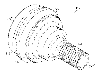
Figure 2 is an isometric view of the hybrid overrunning clutch, according to
an
illustrative embodiment;
Figure 3 is a partially exploded view of the hybrid overrunning clutch,
according to an
illustrative embodiment;
Page 2
CA 02792379 2012-10-10
Figure 4 is a cross-sectional view of the hybrid overrunning clutch, taken
from
section lines 4-4 in Figure 2, according to the illustrative embodiment;
Figure 5 is a schematic view of a method of manufacturing a hybrid overrunning
clutch, according to the illustrative embodiment;
Figure 6 is a detail view taken from the cross-sectional view in Figure 4,
according to
the illustrative embodiment;
Figure 7 is a schematic view of a method of designing a hybrid overrunning
clutch,
according to the illustrative embodiment; and
Figure 8 is a schematic block diagram of a computer system, according to an
illustrative embodiment of the present application.
DESCRIPTION OF THE PREFERRED EMBODIMENT
Illustrative embodiments of the apparatus are described below. In the interest
of
clarity, all features of an actual implementation may not be described in this
specification. It will of course be appreciated that in the development of any
such
actual embodiment, numerous implementation-specific decisions must be made to
achieve the developer's specific goals, such as compliance with system-related
and
business-related constraints, which will vary from one implementation to
another.
Moreover, it will be appreciated that such a development effort might be
complex
and time-consuming but would nevertheless be a routine undertaking for those
of
ordinary skill in the art having the benefit of this disclosure.
In the specification, reference may be made to the spatial relationships
between
various components and to the spatial orientation of various aspects of
components
as the devices are depicted in the attached drawings. However, as will be
recognized by those skilled in the art after a complete reading of the present
application, the devices, members, apparatuses, etc. described herein may be
positioned in any desired orientation. Thus, the use of terms such as "above,"
"below," "upper," "lower," or other like terms to describe a spatial
relationship
between various components or to describe the spatial orientation of aspects
of such
components should be understood to describe a relative relationship between
the
Page 3
CA 02792379 2012-10-10
components or a spatial orientation of aspects of such components,
respectively, as
the device described herein may be oriented in any desired direction.
The embodiments of the present application include a hybrid overrunning
clutch, a
method of making a hybrid overrunning clutch, and a method of designing a
hybrid
overrunning clutch.
Referring to Figure 1, a rotorcraft 101 is illustrated. Rotorcraft 101
includes a
fuselage 103, a landing gear 105, a tail member 107, and a rotor system 109.
An
engine 111 provides torque to rotor system 109 via a driveshaft 113. An
overrunning
clutch 115 is operably associated with driveshaft 113 and engine 111. It
should be
appreciated that rotorcraft 101 is merely illustrative of a variety of
aircraft that can
implement hybrid overrunning clutch 115. Other aircraft implementations can
include
hybrid aircraft, tilt rotor aircraft, unmanned aircraft, gyrocopters, and a
variety of
helicopter configurations, to name a few examples. Further, the methods
disclosed
herein can be implemented to design and manufacture a hybrid overrunning
clutch
for a variety of aircraft implementations.
Referring to Figures 2-4, an example hybrid overrunning clutch 115 is
illustrated.
Clutch 115 includes a metal outer race 119 and a composite outer ring 117. An
engine output provides torque to an input 123 of clutch 115. A clutch
mechanism
127 unidirectionally allows torque to be transferred from input 123 to an
output 121,
the output 121 being configured for coupling to drive shaft 113. During
operation,
clutch mechanism 127 engages an inner race 125 so that torque is
unidirectionally
transferred from input 123 to output 121. Clutch mechanism 127 can be any
mechanical system that is configured to unidirectionally transmit torque
within an
overrunning clutch. Clutch mechanism 127 can include sprag elements, roller
ramp
elements, or ratchet elements, to name a few illustrative examples of clutch
mechanisms.
During operation, torque engagement produces an outward radial force against
metal outer race 119 and a composite outer ring 117. Composite outer ring 117
is
preferably a carbon/resin composite ring that is optimally sized for assembly
with
metal outer race 119. One exemplary composite system is M55J/RS-3C Cyanate
resin system; however, it should be appreciated that composite outer ring 117
may
Page 4
CA 02792379 2012-10-10
be formed from other composite fiber/resin systems. Metal outer race 119 is
preferably formed from a steel alloy, such as steel alloy AISI 9310; however,
other
metals alloys and compositions may be used. Composite outer ring 117 is
configured to provide the tensile strength and stiffness to withstand and
react the
outward radial forces exhibited thereon by engagement of clutch mechanism 127.
The composite outer ring 117 provides significant weight reduction over
conventional
clutch devices that rely solely upon a metal outer race to react all of the
outward
radial forces.
As discussed further in regard to method 501, composite outer ring 117 is
preloaded
in tension as a result of the unique assembly of metal outer race 119 and
composite
outer ring 117. Further, the material ratio between composite outer ring 117
and
metal outer race 119 is specifically tuned to provide optimal stiffness and
deformation during operation, so as to provide proper engagement of clutch
mechanism 127 throughout the operation temperature range. In one illustrative
embodiment, the operational temperature range is approximately -40 F to 280 F.
It
should be appreciated that the temperature range is meant for illustrative
purposes
and not meant to be limiting. For example, in another embodiment, the
operation
temperature range can be -65 F to 305 F. In the preferred embodiment, an
adhesive is not required between metal outer race 119 and composite outer ring
117; however, an alternative embodiment can include adhesive layer for bonding
metal outer race 119 and composite outer ring 117. In the preferred
embodiment,
thermal expansion of metal outer race 119 is relied upon to keep composite
outer
ring 117 in tension, even at the lower end of the operational temperature
range.
A retaining ring 129 can be used to ensure retention of composite outer ring
117 at
temperatures near the lower operation temperature range and below. In the
illustrated embodiment, retaining ring 129 is formed with a shape memory
alloy, such
as a nickel/titanium alloy. As discussed further herein with regard to method
501,
retaining ring 129 is configured so that an application of heat causes it to
shrink and
fit into a recessed groove in metal outer race 119.
Hybrid overrunning clutch 115 is uniquely configured so that composite outer
ring
117 is easily replaceable if damaged. Replacing composite outer ring 117 can
be
accomplished by cutting and removing the damaged composite outer ring 117 and
Page 5
CA 02792379 2012-10-10
the retaining ring 129. Subsequently, a new composite outer ring 117 and
retaining
ring can be installed as outlined in step 307 and step 309, discussed further
herein.
In an alternative embodiment of hybrid overrunning clutch 115, a ceramic ring,
or
other material having a high stiffness to weight ratio, is located within an
inner
portion of inner race 125 so as to replace a portion of steel in inner race
125. Such
an embodiment can also include composite outer ring 117 located around metal
outer race 119.
Referring now to Figure 5, a method 501 of manufacturing hybrid overrunning
clutch
115 is schematically illustrated. A step 503 includes manufacturing metal
outer race
119 with a standard manufacturing process, such as machining or casting, for
example. A step 505 includes manufacturing composite outer ring 117. Step 505
can include using any variety of composite manufacturing processes. For
example,
step 505 can include laying up pre-impregnated composite fiber strips onto a
mandrel, the mandrel having an outside tooled surface that represents the
desired
diameter of the inner surface of composite outer ring 117. Preferably, step
505
includes completely curing composite outer ring 117 prior to assembling
composite
outer ring 117 with metal outer race 119 in a step 507. Furthermore, as
discussed
further in regard to step 507, the inner diameter of composite outer ring 117
is
preferably smaller than the outer diameter of metal outer race 119, throughout
the
operational temperature range. This insures that metal outer race 119
generates a
tension preload on composite outer ring 117 during operation of clutch 115.
Still referring to Figure 5, step 507 includes assembling metal outer race 119
and
composite outer ring 117. In the preferred embodiment, the metal outer race
119 is
cold soaked at a temperature below the lowest operational temperature of
clutch
115. For example, if the lowest operational temperature of clutch 115 is -40
F, then
metal outer race 119 is preferably soaked below -40 F. In one embodiment, step
507 includes cold soaking metal outer race 119 at approximately -200 F. The
cold
soaking of metal outer race 119 creates sufficient thermal shrinkage so that
composite outer ring 117 can be slipped over metal outer race 119. Step 507
further
includes allowing the mated metal outer race 119 and composite outer ring 117
to
gradually warm to an ambient temperature. As the mated metal outer race 119
and
composite outer ring 117 warm, the metal outer race 119 expands at a greater
rate
Page 6
CA 02792379 2012-10-10
than the composite outer ring. At an ambient temperature, metal outer race 119
exerts an outward radial force upon composite outer ring 117 so as to create a
preload in composite outer ring 117. As further stated above, the outer
diameter of
metal outer race 119 and the inner diameter composite outer ring 117 are
configured
so that metal outer race 119 keeps composite outer ring 117 in a tension
preload
through the operating temperature range of clutch 115.
Still referring to Figure 5, method 501 can include a step 509 of installing
retaining
ring 129 to ensure retention of composite outer ring 117 at temperatures near
the
lower operation temperature range and below. Retaining ring 129 is configured
so
that an application of heat causes it to shrink and fit into a recessed groove
in metal
outer race 119, thus step 509 includes locating retaining ring 129 approximate
to the
recessed groove and subjecting the retaining ring 129 to an elevated
temperature so
as to cause retaining ring 129 to shrink and tightly fit into the recessed
groove.
Referring now also to Figure 7, a method 701 of designing a hybrid overrunning
clutch is schematically illustrated. Hybrid overrunning clutch 115 is required
to be
dependable and operate effectively in a broad temperature range. Because
hybrid
overrunning clutch 115 is an essential drive train component on an aircraft, a
failure
can be catastrophic. As such, it is essential that the clutch mechanism 127
effectively transmit torque throughout the broad temperature range. Therefore,
method 701 enables a hybrid overrunning clutch 115 to be designed taking into
account unique considerations of a hybrid overrunning clutch operational in an
aircraft.
Method 701 can include a step 703 that involves analyzing the mismatch in the
coefficients of thermal expansion of both composite outer ring 117 and metal
outer
race 119. Step 701 is important because metal outer race 119 has a much higher
coefficient of thermal expansion than composite outer ring 117. This means
that the
outer race (composite outer ring 117 and metal outer race 119) and inner race
125
grow at different rates, so the sizes need to be designed so that the annular
space
between them is optimal at the temperature at which the hybrid overrunning
clutch
115 normally operates so that clutch mechanism 127 operates most effectively
at the
normal operating temperature. Further, metal outer ring 119 needs to be
configured
without a substantially thicker area in one location that could cause "bell-
mouthing"
Page 7
CA 02792379 2012-10-10
or a bending due to the thick portion of steel wanting to thermally expand
more than
the adjacent areas.
Method 701 also includes a step 705 for analyzing differences in stiffness of
the
composite outer ring 117 and metal outer race 119. Though the stiffness of
composite outer ring 117 in the hoop direction is similar to the stiffness of
the metal
outer race 119, the stiffness of composite outer ring 117 is lower in the
axial
direction. This means that a flat composite outer ring 117 would tend to bend
more
in the middle when operationally loaded, as compared to the forward and aft
portions
of the composite outer ring 117. Such a bending deformation could negatively
affect
the torque transfer engagement of clutch mechanism 127.
Method 701 also includes a step 707 for configuring the geometry of composite
outer
ring 117 and metal outer race 119. Referring now also to Figure 6, step 707
can be
described in regard to the geometry of composite outer ring 117 and metal
outer
race 119 of hybrid overrunning clutch 115. The geometry of metal outer race
119 is
designed with consideration of the analysis in step 703 by having a steel
portion A to
balance a steel portion B, thereby preventing "bell-mouthing" that could
otherwise
occur with changing temperature if steel portion A were to be removed and
replace
by composite outer ring 117. Further, the geometry of composite outer ring 117
is
designed with consideration of the analysis in step 705 by having a thicker
portion T1
near the middle as compared to the end portions. The thicker portion T1 acts
to
compensate for the material stiffness differential between composite outer
ring 117
and metal outer race 119 that could otherwise cause excessive bending in the
middle of composite outer ring 117.
Referring now to Figure 8, a computer system 801 is schematically illustrated.
System 801 is configured for performing one or more functions with regard to
method 701, as well as other methods or processes described herein.
The system 801 can include an input/output (I/0) interface 803, an analysis
engine
805, and a database 807. Alternative embodiments can combine or distribute the
input/output (I/0) interface 803, analysis engine 805, and database 807, as
desired.
Embodiments of the system 801 can include one or more computers that include
one
or more processors and memories configured for performing tasks described
herein.
Page 8
CA 02792379 2012-10-10
This can include, for example, a computer having a central processing unit
(CPU)
and non-volatile memory that stores software instructions for instructing the
CPU to
perform at least some of the tasks described herein. This can also include,
for
example, two or more computers that are in communication via a computer
network,
where one or more of the computers include a CPU and non-volatile memory, and
one or more of the computer's non-volatile memory stores software instructions
for
instructing any of the CPU(s) to perform any of the tasks described herein.
Thus,
while the exemplary embodiment is described in terms of a discrete machine, it
should be appreciated that this description is non-limiting, and that the
present
description applies equally to numerous other arrangements involving one or
more
machines performing tasks distributed in any way among the one or more
machines.
It should also be appreciated that such machines need not be dedicated to
performing tasks described herein, but instead can be multi-purpose machines,
for
example computer workstations, that are suitable for also performing other
tasks.
The I/0 interface 803 can provide a communication link between external users,
systems, and data sources and components of the system 801. The I/0 interface
803 can be configured for allowing one or more users to input information to
the
system 801 via any known input device. Examples can include a keyboard, mouse,
touch screen, and/or any other desired input device. The I/0 interface 803 can
be
configured for allowing one or more users to receive information output from
the
system 801 via any known output device. Examples can include a display
monitor, a
printer, and/or any other desired output device. The I/0 interface 803 can be
configured for allowing other systems to communicate with the system 801. For
example, the I/0 interface 803 can allow one or more remote computer(s) to
access
information, input information, and/or remotely instruct the system 801 to
perform
one or more of the tasks described herein. The I/0 interface 803 can be
configured
for allowing communication with one or more remote data sources. For example,
the
I/0 interface 803 can allow one or more remote data source(s) to access
information,
input information, and/or remotely instruct the system 801 to perform one or
more of
the tasks described herein.
The database 807 provides persistent data storage for system 801. While the
term
"database" is primarily used, a memory or other suitable data storage
arrangement
Page 9
CA 02792379 2014-05-15
may provide the functionality of the database 807. In alternative embodiments,
the
database 807 can be integral to or separate from the system 801 and can
operate on
one or more computers. The database 807 preferably provides non-volatile data
storage for any information suitable to support the operation of the system
801,
including various types of data discussed further herein.
The analysis engine 805 can be configured for analyzing the mismatch in the
coefficients of thermal expansion of both composite outer ring 117 and metal
outer
race 119, analyzing differences in stiffness of the composite outer ring 117
and metal
outer race 119, and configuring the geometry of composite outer ring 117 and
metal
outer race 119. The analysis engine 805 can include various combinations of
one or
more processors, memories, and software components.
The hybrid clutch of the present application provides significant advantages,
including: 1) providing an outer race member having composite material to
lighten
the total weight of the clutch; 2) providing a method of manufacturing the
hybrid
clutch so that a outer metal race creates a preload on the composite outer
ring
throughout the operational temperature range of the clutch; 3) providing a
composite
outer ring and steel outer race assembly configured to provide adequate
annular
space for operation of the clutch mechanism within the operational temperature
range; 4) providing an easily repairable composite outer ring and method of
repair;
and 5) providing a method of designing a hybrid overrunning clutch.
The particular embodiments disclosed above are illustrative only, as the
apparatus
may be modified and practiced in different but equivalent manners apparent to
those
skilled in the art having the benefit of the teachings herein. Modifications,
additions,
or omissions may be made to the apparatuses described herein without departing
from the scope of the invention. The components of the apparatus may be
integrated or separated. Moreover, the operations of the apparatus may be
performed by more, fewer, or other components.
It is evident that the particular embodiments disclosed above may be altered
or
modified within the scope of the invention disclosed. Modifications which fall
within
the scope of the present invention will be apparent to those skilled in the
art, in light
Page 10
CA 02792379 2014-05-15
of a review of this disclosure, and such modifications are intended to fall
within the
appended claims.
Page 11