Language selection

Search

Patent 2792393 Summary

Third-party information liability

Some of the information on this Web page has been provided by external sources. The Government of Canada is not responsible for the accuracy, reliability or currency of the information supplied by external sources. Users wishing to rely upon this information should consult directly with the source of the information. Content provided by external sources is not subject to official languages, privacy and accessibility requirements.

Claims and Abstract availability

Any discrepancies in the text and image of the Claims and Abstract are due to differing posting times. Text of the Claims and Abstract are posted:

  • At the time the application is open to public inspection;
  • At the time of issue of the patent (grant).
(12) Patent: (11) CA 2792393
(54) English Title: LIFTING UNIT FOR LIFTING A ROTOR OF A WIND ENERGY INSTALLATION
(54) French Title: UNITE DE LEVAGE POUR LEVER UN ROTOR D'UNE EOLIENNE
Status: Expired and beyond the Period of Reversal
Bibliographic Data
(51) International Patent Classification (IPC):
  • B66C 01/12 (2006.01)
(72) Inventors :
  • LUELKER, FRANK (Germany)
(73) Owners :
  • WOBBEN PROPERTIES GMBH
(71) Applicants :
  • WOBBEN PROPERTIES GMBH (Germany)
(74) Agent: OYEN WIGGS GREEN & MUTALA LLP
(74) Associate agent:
(45) Issued: 2015-01-06
(86) PCT Filing Date: 2011-03-23
(87) Open to Public Inspection: 2011-09-29
Examination requested: 2012-09-06
Availability of licence: N/A
Dedicated to the Public: N/A
(25) Language of filing: English

Patent Cooperation Treaty (PCT): Yes
(86) PCT Filing Number: PCT/EP2011/054432
(87) International Publication Number: EP2011054432
(85) National Entry: 2012-09-06

(30) Application Priority Data:
Application No. Country/Territory Date
20 2010 004 093.0 (Germany) 2010-03-23

Abstracts

English Abstract


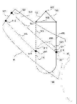
There is provided a lifting unit for lifting a rotor of a wind power
installation. The lifting unit has at least one first sling (100) for looping
around a region of a rotor blade on a rotor of the wind power installation,
which region is near the rotor blade root, at least one transverse strut
(900), at least one first and second strut or sling portion (300, 400), and at
least one first and second hinge unit (200, 210). The at least one first and
second struts or sling portions (300, 400) extend between the at least one
first and second hinge units (200, 210) and the transverse strut (900). The
lifting unit further has at least one second sling (500) having first and
second sling portions (510, 520) and a strut (530). The first ends of the
first and second sling portions (510, 520) are fixed to the first and second
hinge units (200, 210) The second sling (500) is adapted to be arranged
around a rotor blade stub.


French Abstract

L'invention concerne une unité de levage pour lever un rotor d'une éolienne. L'unité de levage présente au moins une première élingue (100) à enrouler autour d'une région proche de la racine d'une pale de rotor sur un rotor de ladite éolienne, au moins une traverse (900), au moins une première et une deuxième entretoise ou élingue partielle (300, 400) et au moins une première et une deuxième unité d'articulation (200, 210). Ces au moins une première et une deuxième entretoises ou élingues partielles (300, 400) s'étendent entre la première et la deuxième unité d'articulation (200, 210) et la traverse (900). L'unité de levage présente en outre au moins une deuxième élingue (500) qui présente une première et une deuxième élingue partielle (510, 520) et une entretoise (530). Les premières extrémités des première et deuxième élingues partielles (510, 520) sont fixées à la première et la deuxième unité d'articulation (200, 210). La deuxième élingue (500) est conçue pour être disposée autour d'une extrémité de pale de rotor.

Claims

Note: Claims are shown in the official language in which they were submitted.


6
CLAIMS
1. A lifting unit for lifting a rotor of a wind power installation with at
least one rotor blade, comprising
at least one first sling (100) for looping around a region of a rotor
blade on the rotor of the wind power installation, which region is near a
root of the rotor blade,
at least one transverse strut (900),
at least one first and second strut or sling portion (300, 400), and
at least one first and second hinge unit (200, 210), wherein the first
and second struts or sling portions (300, 400) extend between the first and
second hinge units (200, 210) and the transverse strut (900), and
at least one second sling (500) having first and second sling portions
(510, 520) and a strut (530), wherein the first ends of the first and second
sling portions (510, 520) are fixed to the first and second hinge units (200,
210), wherein the second sling (500) is adapted to be arranged around a
rotor blade stub.
2. The lifting unit according to claim 1 wherein the transverse strut
(900) is of such a length that the first and second hinge units (200, 210) do
not come into contact with the rotor blades or the rotor of the wind power
installation.
3. The lifting unit according to claim 1 or claim 2 wherein the first
and second hinge units (200, 210) have a first, a second and a third end
(210, 220, 230), wherein the second sling (500) is coupled to the third end
(230), the first sling (100) is coupled to the second end and the first and
second sling portions (300, 400) are coupled to the first end,
wherein the third end (230) is rotatably or pivotably coupled to the
second end (220).

Description

Note: Descriptions are shown in the official language in which they were submitted.


CA 02792393 2014-05-16
1
Lifting unit for lifting a rotor of a wind energy installation
The present invention concerns a lifting unit for lifting a rotor of a
wind power installation.
A lifting unit can be used for mounting a rotor to a pod with rotor
blades carried thereon.
Thus an object of the present invention is to provide a lifting unit
which can be used in mounting a rotor including the rotor blades to the pod
on a pylon of a wind power installation.
That object is attained by a lifting unit as described below.
Thus there is provided a lifting unit for lifting a rotor of a wind power
installation. The lifting unit has at least one first sling for looping around
a
region of a rotor blade, that is near to the rotor blade root, on a rotor of
the
wind power installation, at least one transverse strut, at least one first and
second struts or sling portions and at least one first and second hinge units.
The at least one first and second struts or sling portions extend between
the at least one first and second hinge units and the transverse strut. The
lifting unit further has at least one second sling having first and second
sling portions and a strut. The first ends of the first and second sling
portions are fixed to the first and second hinge units. The second sling is
adapted to be arranged around a rotor blade stub.
In an aspect of the present invention the length of the transverse
strut is such that the first and second hinge units do not come into contact
with the rotor blades or the rotor of the wind power installation.
In a further aspect of the invention the first and second hinge units
have first, second and third ends. The second sling is coupled to the third
end. The first sling is coupled to the second end and the first and second
sling portions are coupled to the third end of the hinge unit. The third end
is rotatably or pivotably coupled to the second end.

CA 02792393 2014-05-16
-
2
By means of the lifting unit according to the invention it is possible
for example to fit a spinner or a rotor of a wind power installation inclusive
of the rotor blades.
The lifting unit preferably has two slings which can extend around
the rotor blade in the region of the root of the rotor blade. Those slings can
then be connected to a crane hook by way of intermediate members or
intermediate elements or hinge units so that the rotor or the spinner
inclusive of for example three rotor blades mounted to the rotor can be
raised. The two slings which are provided around the rotor blade in the
region of the rotor blade root serve to carry the load when lifting the entire
structure. The lifting unit is intended to serve to pick up the rotor plus the
three at least partially mounted rotor blades from the ground and convey
them to the pod on to the pylon of the wind power installation.
Advantages and embodiments by way of example of the invention
are described in greater detail hereinafter with reference to the drawing.
Figure 1 shows a diagrammatic view of a lifting unit according to a
first embodiment,
Figures 2A to 2C show various views of a hinge unit of the lifting unit
of Figure 1, and
Figure 3 shows a diagrammatic view of a lifting unit according to a
first embodiment with a rotor blade and a rotor of a wind power
installation.
Figure 1 shows a diagrammatic view of a lifting unit according to a
first embodiment. The lifting unit has a first sling or loop 100 having a
first
and second end 110, 120, first and second struts or sling portions 300, 400
each having a first and a second end 310, 320; 410, 420, first and second
hinge units 200 and a connecting bar or transverse strut 900 between the
second ends of the first and second struts 300, 400. The first end 110 of
the first sling 100 is connected to the first hinge 200 and the second end
120 of the first sling 100 is connected to the second hinge 210. In addition
the first ends 310, 410 of the first and second struts 300, 400 are

CA 02792393 2012-09-06
3
respectively connected to the first and second hinges 200, 210. The lifting
unit further has a second sling 500 having first and second loops or sling
portions 510, 520. The first and second sling portions 510, 520 respectively
have a first and a second end 511, 521 and a second end 512, 522. The
second ends 512, 522 of the first and second slings 510, 520 are connected
together by way of a third strut 530.
The first and second hinges 200, 210 have a first end for receiving
an end of the first sling 100, a second end for receiving the first ends of
the
first and second struts 300, 400 and a third end for receiving the first ends
511, 521 of the first and second sling portions 510, 520. In this case the
third end is rotatable or pivotable relative to the first or second end
(preferably the second end).
The first and second struts 300, 400 can also be in the form of sling
portions.
The first sling 100 serves to be arranged at the side or end of the
rotor blade of a wind power installation, that is towards the rotor blade
root. The first sling 100 is therefore of such a configuration that it can fit
snugly around the region of the root of the rotor blade.
The transverse strut 900 is preferably of such a length that the first
and second hinge units 200, 210 cannot contact the rotor blade or the
spinner and thus damage them. In addition the third strut 530 is of such a
length that the first and second sling portions 510, 520 cannot at any time
come into contact with the rotor blade or a first portion of the rotor blade.
The third strut 530 is preferably arranged at an end, opposite to the
rotor blade root, of a rotor blade stub of a rotor blade of a wind power
installation (that is to say the rotor blade can be of a multi-part structure
and the rotor blade stub is mounted together with the rotor of the rotor
blade installation to the pod by means of the lifting unit) so that the sling
portions 510, 520 extend between the first and second hinge units 200,
210 and the third strut 530 without in that case touching the rotor blade.
Figures 2A to 2C show various views of the hinge units according to
the first embodiment.

CA 02792393 2012-09-06
4
Figure 2A shows a diagrammatic side view of the hinge unit 200
according to the first embodiment. The hinge unit has a first, a second and
a third end 210, 220 and 230. In this case the first end 210 is connected to
the second end 220 and the third end 230 is connected to the second end
220. In this arrangement the third end 230 is connected to the second end
220 in such a way that it is rotatable or pivotable about the second end
220. Provided at the first end 210 is a first bar 211, provided at the second
end 220 is a second bar 221 and provided at the third end 230 is a third
bar 231.
Figure 2B shows a cross-section along line A-A in Figure 2A. Figure
2A shows the bar 221 and the bar 231.
Figure 2C shows a perspective view of the hinge unit according to
the first embodiment. The hinge unit has a first end 210, a second end 220
and a third end 230. In this case the third end 230 is rotatably or pivotably
connected to the second end 220. The third end 230 with the bar 231
serves to receive the first ends of the first and second bars 300, 400.
The first end 210 serves to receive the first or second end 110, 120
of the first sling 100 and the second end 220 with the bar 221 serves to
receive the first or second sling 510, 520.
Figure 3 shows a diagrammatic view of the lifting unit according to a
first embodiment together with a rotor blade and a pod housing of a wind
power installation. The wind power installation has a rotor blade or a rotor
blade stub as well as a pod or a pod housing 200. At its one side the rotor
blade is connected to the pod 200. The first sling 100 is passed around the
rotor blade tip. A second sling 500 is passed around the rotor blade stub.
Thus the third strut 530 bears against an end of the rotor blade (stub end).
The first strut or sling portion 300 is passed behind the rotor blade and the
second strut or sling portion 400 is passed in front of the rotor blade (in
Figure 3). In that way the lifting unit according to the first embodiment can
pick up a rotor blade of a wind power installation.
Preferably two lifting units according to the first embodiment are
used, to lift a pod and rotor blades fixed thereto, for mounting to the wind

CA 02792393 2012-09-06
power installation. For example a crane hook can engage a portion 800 to
lift the two lifting units of the rotor of the wind power installation.
The lifting unit according to the invention is advantageous because it
makes it possible to lift a rotor of a wind power installation from a lying
5 condition (the rotor is lying on the ground). The design
configuration of the
hinge units 200, 210 make it possible that the lifting unit or the first sling
100 does not slip or scrape along the rotor blade. That can also be achieved
by the rotor blades 10 being fixed rotatably to the pod housing or the
spinner.

Representative Drawing
A single figure which represents the drawing illustrating the invention.
Administrative Status

2024-08-01:As part of the Next Generation Patents (NGP) transition, the Canadian Patents Database (CPD) now contains a more detailed Event History, which replicates the Event Log of our new back-office solution.

Please note that "Inactive:" events refers to events no longer in use in our new back-office solution.

For a clearer understanding of the status of the application/patent presented on this page, the site Disclaimer , as well as the definitions for Patent , Event History , Maintenance Fee  and Payment History  should be consulted.

Event History

Description Date
Time Limit for Reversal Expired 2022-09-23
Letter Sent 2022-03-23
Letter Sent 2021-09-23
Letter Sent 2021-03-23
Common Representative Appointed 2019-10-30
Grant by Issuance 2015-01-06
Inactive: Cover page published 2015-01-05
Pre-grant 2014-10-16
Inactive: Final fee received 2014-10-16
Notice of Allowance is Issued 2014-08-04
Letter Sent 2014-08-04
Notice of Allowance is Issued 2014-08-04
Inactive: Q2 passed 2014-07-10
Inactive: Approved for allowance (AFA) 2014-07-10
Letter Sent 2014-06-27
Inactive: Single transfer 2014-06-16
Amendment Received - Voluntary Amendment 2014-05-16
Inactive: S.30(2) Rules - Examiner requisition 2013-11-21
Inactive: Report - No QC 2013-11-07
Inactive: Cover page published 2012-11-05
Inactive: First IPC assigned 2012-10-29
Letter Sent 2012-10-29
Inactive: Acknowledgment of national entry - RFE 2012-10-29
Inactive: IPC assigned 2012-10-29
Application Received - PCT 2012-10-29
National Entry Requirements Determined Compliant 2012-09-06
Request for Examination Requirements Determined Compliant 2012-09-06
All Requirements for Examination Determined Compliant 2012-09-06
Application Published (Open to Public Inspection) 2011-09-29

Abandonment History

There is no abandonment history.

Maintenance Fee

The last payment was received on 2014-02-07

Note : If the full payment has not been received on or before the date indicated, a further fee may be required which may be one of the following

  • the reinstatement fee;
  • the late payment fee; or
  • additional fee to reverse deemed expiry.

Patent fees are adjusted on the 1st of January every year. The amounts above are the current amounts if received by December 31 of the current year.
Please refer to the CIPO Patent Fees web page to see all current fee amounts.

Owners on Record

Note: Records showing the ownership history in alphabetical order.

Current Owners on Record
WOBBEN PROPERTIES GMBH
Past Owners on Record
FRANK LUELKER
Past Owners that do not appear in the "Owners on Record" listing will appear in other documentation within the application.
Documents

To view selected files, please enter reCAPTCHA code :


To view images, click a link in the Document Description column. To download the documents, select one or more checkboxes in the first column and then click the "Download Selected in PDF format (Zip Archive)" or the "Download Selected as Single PDF" button.

List of published and non-published patent-specific documents on the CPD .

If you have any difficulty accessing content, you can call the Client Service Centre at 1-866-997-1936 or send them an e-mail at CIPO Client Service Centre.


Document
Description 
Date
(yyyy-mm-dd) 
Number of pages   Size of Image (KB) 
Drawings 2012-09-05 3 37
Abstract 2012-09-05 1 21
Claims 2012-09-05 1 35
Description 2012-09-05 5 195
Representative drawing 2012-11-04 1 7
Description 2014-05-15 5 193
Claims 2014-05-15 1 35
Abstract 2014-12-16 1 21
Representative drawing 2014-12-23 1 6
Acknowledgement of Request for Examination 2012-10-28 1 175
Notice of National Entry 2012-10-28 1 202
Courtesy - Certificate of registration (related document(s)) 2014-06-26 1 102
Commissioner's Notice - Application Found Allowable 2014-08-03 1 162
Commissioner's Notice - Maintenance Fee for a Patent Not Paid 2021-05-03 1 536
Courtesy - Patent Term Deemed Expired 2021-10-13 1 539
Commissioner's Notice - Maintenance Fee for a Patent Not Paid 2022-05-03 1 541
PCT 2012-09-05 14 487
Correspondence 2014-10-15 2 59