Note: Descriptions are shown in the official language in which they were submitted.
CA 02793120 2012-09-12
WO 2011/113055 PCT/US2011/028382
PORTABLE UNIVERSAL SERIAL BUS (USB) CABLE ASSEMBLY
BACKGROUND
Field
[0001] The present disclosure relates to a portable Universal Serial Bus (USB)
cable, and more particularly, to a compact and portable USB cable that can be
configured as a keychain accessory.
Description of Related Art
[0002] USB cables are well-known in the art. However, there is a need for a
more
compact portable USB cable assembly that can be transported easily by a user,
eliminates the tangle and hassle of loose wires, and is ergonomically and
aesthetically
pleasing to the user.
SUMMARY
[0003] In one aspect of the disclosure, a Universal Serial Bus (USB) cable
assembly for connecting a portable electronic device to a host device includes
a USB
cable, an upstream connector, a downstream connector connected to the upstream
connector by the USB cable, and a main body section having an upstream
connector
port configured to slidably receive the upstream connector and a downstream
connector port configured to slidably receive the downstream connector,
wherein the
USB cable is slidably secured to the main body section.
-1-
CA 02793120 2012-09-12
WO 2011/113055 PCT/US2011/028382
[0004] In another aspect of the disclosure, the USB cable assembly comprises
an
attachment mechanism. The attachment mechanism may be a through-hole formed in
the main body section.
[0005] In yet another aspect of the disclosure, a USB cable assembly includes
an
upstream connector section having a housing and an upstream connector secured
to
the housing, a downstream connector section having a first downstream housing,
a
first downstream connector secured to the first downstream housing, a second
downstream housing, and a second downstream connector secured to the second
housing, a main body section having an upstream connector port configured to
slidably
receive the upstream connector and a downstream connector port configured to
slidably receive the first and second downstream housings, and a USB cable
that joins
the upstream connector section, the main body section, and the downstream
connector
section.
[0006] In yet another aspect of the disclosure, a cable assembly for
connecting a
portable electronic device to a host device includes a cable an upstream
connector a
downstream connector connected to the upstream connector by the cable, and a
main
body section having an attachment mechanism comprising a through hole formed
in
the main body, the through hole including on a side a carabiner clip
comprising a
spring-loaded hinged inwardly movable portion completing the through hole.
[0007] It is understood that other aspects of a USB cable assembly will become
readily apparent to those skilled in the art from the following detailed
description,
wherein it is shown and described only exemplary configurations of a cable
assembly.
As will be realized, the invention includes other and different aspects of a
cable
-2-
CA 02793120 2012-09-12
WO 2011/113055 PCT/US2011/028382
assembly and the various details presented throughout this disclosure are
capable of
modification in various other respects, all without departing from the spirit
and scope of
the invention. Accordingly, the drawings and the detailed description are to
be
regarded as illustrative in nature and not as restrictive.
BRIEF DESCRIPTION OF THE DRAWINGS
[0008] Fig. 1 is a perspective view of a USB cable assembly in a first
configuration,
in accordance with aspects of the present invention;
[0009] Fig. 2 is a top, cutaway view of the USB cable assembly shown in Fig. 1
in a
second configuration, in accordance with aspects of the present invention;
[0010] Fig. 3 is a perspective of the USB cable assembly shown in Fig. 2;
[0011] Fig. 4 is top view of the USB cable assembly shown in Fig. 2;
[0012] Fig. 5 is a left side view of the USB cable assembly shown in Fig. 2;
[0013] Fig. 6 is a right side view of the USB cable assembly shown in Fig. 2;
[0014] Fig. 7 is a top view of the USB cable assembly shown in Fig. 2;
[0015] Fig. 8 is a bottom view of the USB cable assembly shown in Fig. 2;
[0016] Fig. 9 is a perspective view of a USB cable assembly in a first
configuration,
in accordance with aspects of the present invention;
[0017] Fig. 10 is a top, cutaway view of the USB cable assembly shown in Fig.
9 in
a second configuration, in accordance with aspects of the present invention;
[0018] Fig. 11 is a perspective of the USB cable assembly shown in Fig. 10;
[0019] Fig. 12 is top view of the USB cable assembly shown in Fig. 10;
[0020] Fig. 13 is a left side view of the USB cable assembly shown in Fig. 10;
and
-3-
CA 02793120 2012-09-12
WO 2011/113055 PCT/US2011/028382
[0021] Fig. 14 is a right side view of the USB cable assembly shown in Fig.
10.
[0022] Figs. 15-16 are two perspective views of an embodiment of a cable
assembly with a carabiner clip, in accordance with aspects of the present
disclosure.
DETAILED DESCRIPTION
[0023] The present invention is described more fully hereinafter with
reference to
the accompanying drawings, in which various aspects of a compact and portable
USB
cable assembly are shown. This invention, however, may be embodied in many
different forms and should not be construed as limited by the various aspects
of the
USB cable assembly presented herein. The detailed description of the USB cable
assembly is provided below so that this disclosure will be thorough and
complete, and
will fully convey the scope of the present invention to those skilled in the
art.
[0024] The detailed description may include specific details for illustrating
various
aspects of a USB cable assembly. However, it will be apparent to those skilled
in the
art that the invention may be practiced without these specific details. In
some
instances, well known elements may be shown in block diagram form, or omitted,
to
avoid obscuring the inventive concepts presented throughout this disclosure.
[0025] Various aspects of a USB cable assembly may be illustrated by
describing
components that are coupled, attached or connected together. As used herein,
the
terms "coupled", "attached", and "connected" may be used to indicate either a
direct
connection between two components or, where appropriate, an indirect
connection to
one another through intervening or intermediate components. In contrast, when
a
-4-
CA 02793120 2012-09-12
WO 2011/113055 PCT/US2011/028382
component is referred to as being "directly coupled", "directly attached" or
"directly
connected" to another component, there are no intervening elements present.
[0026] Relative terms such as "lower" or "bottom" and "upper" or "top" may be
used
herein to describe one element's relationship to another element illustrated
in the
drawings. It will be understood that relative terms are intended to encompass
different
orientations of a USB cable assembly in addition to the orientation depicted
in the
drawings. By way of example, if a USB cable assembly in the drawings is turned
over,
elements described as being on the "bottom" side of the other elements would
then be
oriented on the "top" side of the other elements. The term "bottom" can
therefore
encompass both an orientation of "bottom" and "top" depending on the
particular
orientation of the apparatus.
[0027] Various aspects of a USB cable assembly may be illustrated with
reference
to one or more exemplary embodiments. As used herein, the term "exemplary"
means
"serving as an example, instance, or illustration," and should not necessarily
be
construed as preferred or advantageous over other embodiments of a USB cable
assembly disclosed herein.
[0028] The USB cable assembly is compact and portable so that it can easily be
stowed for transport, greatly enhancing a consumer's ability to use the USB
cable
assembly to recharge, power, and/or perform data transfer/synchronization for
one or
more portable electronic devices (PEDs) that rely on a USB port for power,
recharging
and/or data transfer. The USB cable assembly may be configured to provide one
or
more USB 5V connectors for connecting to one or more PEDs when plugged into a
host device, which may be a personal computer, for example.
-5-
CA 02793120 2012-09-12
WO 2011/113055 PCT/US2011/028382
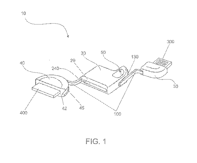
[0029] Fig. 1 provides a perspective view of a USB cable assembly 10 in
accordance with aspects of the present invention. The USB cable assembly 10 is
configured to connect a PED to a host device, such as a computer, for example.
A
USB cable 100 connects an upstream connector 300, which is preferably a male 4
pin
Type A USB connector, to a downstream connector 400, which may be a 30 pin
connector, for example, of the type typically used as a dock connector for an
iPOD or
iPhone . The USB cable 100 may be a shielded cable having two wires, a power
and
a ground wire, for delivering power at 5 volts from the host to the PED, and a
braided
pair of wires for carrying data between the host and the PED. In accordance
with
another aspect of the present invention, the USB cable assembly 10 may be
provided
with a suitable attachment mechanism, such as a screw eye or, as shown in
Figs. 1-4,
a through-hole 50 formed in a main body section 20. The through-hole 50 may be
used to attach the cable assembly 10 to a keychain, such as a wrist coil
keychain, for
example. In this manner, and due to its compact, lightweight and ergonomic
design,
the USB cable assembly 10 may be easily stored and/or transported for
convenient
access and efficient use.
[0030] As depicted in Fig. 1, the USB cable assembly 10 is in an operational
configuration and includes a main body section 20, a detachable upstream
connector
body section 30, and a detachable downstream connector body section 40. The
main
body section 20 includes an upstream connector port 230 (see also Fig. 2) and
a
downstream connector port 240 for slidably receiving the upstream and
downstream
connectors, 300 and 400, respectively. In the operational configuration, the
upstream
and downstream connectors, 300 and 400, are disengaged from the respective
-6-
CA 02793120 2012-09-12
WO 2011/113055 PCT/US2011/028382
upstream and downstream connector ports, 230 and 240, so that the upstream
connector body section 30 and the downstream connector body section 40 may be
separated from the main body section 20. The upstream connector body section
30
and the downstream connector body section 40 remain connected to the main body
section 20 by way of the USB cable 100. Thus, in the operational
configuration, the
upstream connector 300 is available for attachment to a Type A USB connector
port,
for example, on the host device, and the downstream connector 400 is available
for
attachment to the PED.
[0031] As shown in Figs. 2-8, when the USB cable assembly 10 is in a storage
configuration, the upstream and downstream connectors, 300 and 400, are
secured in
the upstream and downstream connector ports, 230 and 240, respectively. The
upstream connector body section 30 and the downstream connector body section
40
mate with the main body section 20 to form a unified body with generally flat,
smooth
front and rear surfaces, and rounded corners and edges. The smooth, rounded
contours of the USB cable assembly 10 allow a user to store the assembly 10 in
garment pockets, for example, without snagging and tearing.
[0032] As shown in the cutaway view of Fig. 2, the main body section 20 may be
formed with an outer casing made of nonconductive material. The outer casing
may
be formed from a combination of two molded shells, for example, or any other
method
of forming a protected enclosure for securing and protecting the upstream
connector
300, the downstream connector 400, and the USB cable 100 connecting the
upstream
connector 300 to the downstream connector 400. The main body section 20 may be
generally hollow, for example, and formed with various features for providing
structural
-7-
CA 02793120 2012-09-12
WO 2011/113055 PCT/US2011/028382
support and positional guidance. For example, as shown in Figure 2, a
structural rib
21 surrounds a periphery of the through-hole 50 and provides structural
support to an
area of the assembly 10 that may be subjected to comparatively high levels of
applied
stress. In addition, along with an outer wall 22, the structural rib 21 may
form an inner
surface of a main body channel 130 that cradles an upstream portion of the USB
cable
100 leading to the upstream connector 300 (see also Figs. 3 and 5).
Longitudinal rib
23 may be configured to form both a longitudinal and a lateral seat for
positional
mating of the upstream connector body section 30 in abutment with the main
body
section 20. A lower portion 24 of the longitudinal rib 23 may, in tandem with
a securing
wall 26, form the side walls of the connector port 230. In this manner, the
lateral
clearance between the lower portion of the longitudinal rib 23 and the
securing wall 26
may be configured to ensure a secure fit of the upstream connector 300 when
the
upstream connector 300 is slidably received into the upstream connector port
230. A
distal end 25 of the longitudinal rib 23 may be used as a positioning means
along a
transverse path of the USB cable 100 as the USB cable 100 passes through the
main
body section 20. A lower end wall 27 and a lower positional rib 28 form the
side walls
of the downstream connector port 240. As shown in Fig. 2, the lower positional
rib 28
may be provided to exert a lateral pressure against the downstream connector
400 for
securing the downstream connector 400 when inserted into the downstream
connector
port 240.
[0033] As shown in Figs. 2-4, the upstream connector body section 30 may be
formed as a parallelepiped with an outer casing made of nonconductive material
formed from a combination of two molded shells, for example. The upstream
-8-
CA 02793120 2012-09-12
WO 2011/113055 PCT/US2011/028382
connector body section 30 may be formed with rounded peripheral edges that
align
with the rounded peripheral edges of the main body section 20 when the
upstream
connector 300 is placed in a stored position, i.e., when fully inserted into
the upstream
connector port 230.
[0034] When in the stored position, the upstream connector body section 30
mates
with the main body section 20 in a position offset to one side of the
longitudinal
centerline of the USB cable assembly 10. As shown in Figs. 2 and 7, an
upstream
cable passage 32 formed in a corner peripheral surface of the upstream
connector
body section 30 aligns with the main body channel 130 to cradle the upstream
portion
of the USB cable 100 along a periphery of the main body section 20. The
upstream
portion of the USB cable 100 enters the outer casing of the upstream connector
body
section 30 through the upstream cable passage 32 and is connected to the
upstream
connector 300. The upstream connector 300 is fixedly attached to the upstream
connector body section 30 so that the upstream connector body section 30
houses and
protects the USB cable 100 connection to the upstream connector 300.
[0035] As shown in Figs. 1-4, the downstream connector body section 40 may be
formed as a half-disc, for example, with an outer casing having a rounded
semicircular
edge 41 and a mating surface 42. The downstream portion of the USB cable 100
enters the outer casing of the downstream connector body section 40 through a
downstream passage 43 and is connected to the downstream connector 400. A
downstream body channel 45 may be formed in the semicircular edge 41 along a
peripheral arc from where the USB cable 100 enters the downstream connector
body
section 40, at the downstream passage 43, to a lateral edge of the mating
surface 42.
-9-
CA 02793120 2012-09-12
WO 2011/113055 PCT/US2011/028382
[0036] When the downstream connector 400 is placed in the stored position,
i.e.,
when fully inserted into the downstream connector port 240, the mating surface
42 of
the main body section 20 abuts an end surface 29 of the downstream connector
body
section 40. As shown in Figs. 1, 5 and 8, a cable passage 142 may be formed in
a
peripheral surface of the main body section 20. The cable passage 142 aligns
with the
downstream body channel 45 to cradle the downstream portion of the USB cable
100
along a periphery of the downstream connector body section 40. The downstream
connector 400 is fixedly attached to the downstream connector body section 40
so that
the downstream connector body section 40 houses and protects the USB cable 100
connection to the downstream connector 400.
[0037] In use, the USB cable assembly 10, which may be secured to a keychain,
for
example, is placed into the operational configuration by slidably removing the
upstream
and downstream connectors, 300 and 400, from the upstream and downstream
connection ports 230 and 240. The unitary design of the cable assembly 10
ensures
that the USB cable 100 remains slidably secured to the main body section 20
when the
upstream and downstream connector body sections 30 and 40 are respectively
disengaged. In this manner, all components of the cable assembly 10 remain
continuously attached at all times, whether or not the cable assembly 10 is
being used
in an operational or storage configuration. Thus, a user will not misplace or
lose a
protective cap, for example, and can be assured that the critical components
of the
cable assembly 10 may always be stored in an efficient, protective manner,
preventing
damage and extending the effective life of the cable assembly 10 indefinitely.
-10-
CA 02793120 2012-09-12
WO 2011/113055 PCT/US2011/028382
[0038] In accordance with another aspect of the present invention, with the
cable
assembly 10 in an operational configuration, a distance that the upstream and
downstream connectors, 300 and 400, can respectively extend away from the main
body section 20 may be adjusted. For example, when initially disengaged from
the
main body section 20, the upstream connector body section 30 and the
downstream
connector body section 40 extend a predetermined distance from the main body
section 20. Because the USB cable 100 is not fixed to the main body section
20, but
slidably passes through the main body section 20, pulling on either of the
upstream
connector body section 30 or the downstream connector body section 40 will
extend
the respective body section 30 or 40 a distance from the main body section 20.
The
other of the upstream connector body section 30 or the downstream connector
body
section 40 will simultaneously retract the same distance toward the main body
section
as the USB cable 100 is pulled through the main body section 20. The length
that
either of the upstream connector body section 30 or the downstream connector
body
section 40 can extend is limited only by the predetermined distance that the
other of
20 the upstream connector body section 30 or the downstream connector body
section 40
initially extends from the main body section 20 upon disengagement from a
stored
configuration.
[0039] Once the cable assemble 10 is opened and configured as desired by the
user, the upstream connector 300 may be connected to an appropriate port on
the host
device, and the downstream connector 400 connected to an appropriate port on
the
PED. The host may thus supply a predetermined current of power to the PED at
5V
-11-
CA 02793120 2012-09-12
WO 2011/113055 PCT/US2011/028382
while simultaneously exchanging data with the PED in accordance with a
specified
USB standard, which may be USB 2.0 or USB 3.0, for example.
[0040] The USB cable assembly 10 may be placed in a storage configuration by
inserting the upstream connector 300 into the upstream connector port 230 so
that the
upstream connector body section 30 seats flush with the main body section 20.
The
downstream connector 400 is inserted into the downstream connector port 240 so
that
the downstream connector body section 40 seats flush with the main body
section 20.
As shown in Fig. 2, when in the storage position, the upstream and downstream
connectors, 300 and 400, occupy an upper and a lower space inside the main
body
section 20 and are separated substantially by a thickness of the USB cable
100. The
upstream portion of the USB cable 100 may be pulled taut and secured into the
main
body channel 130, and the downstream portion of the USB cable 100 may be
pulled
taut and secured into the downstream body channel 45. The channels 130 and 45
effectively shield and protect the USB cable 100 from damage by preventing
exposure
to direct impacts and snags, for example. Due to the compact and efficient
configuration of the USB cable assembly 10, as described above, the assembly
is able
to be lightweight, ergonomic and cost-efficient to manufacture while providing
substantial protection to the critical components of the assembly.
[0041] Figs. 9-14 show another variation of a USB cable assembly 500, in
accordance with aspects of the present invention, in which the USB cable
assembly
500 may be provided with multiple downstream connectors, such as dual mini and
micro USB connectors. As shown in Fig. 9, the USB cable assembly 500 shares
similar aspects with respect to the upstream side of the USB cable assembly
10,
-12-
CA 02793120 2012-09-12
WO 2011/113055 PCT/US2011/028382
including a Type-A upstream connector 800, and a main body section 520
provided
with an upstream connector port 730 for receiving the upstream connector 800
and a
keychain loop 550. The downstream side of the USB cable assembly 500, as
depicted
in Fig. 9, has a first downstream connector 900, which may be a mini-A or mini-
B type
USB connector, and a second downstream connector 950, which may be a micro-A
or
micro-B type USB connector. The first and second downstream connectors, 900
and
950, may secure to and extend from first and second housings 910 and 960,
respectively. The first housing 910 may be formed with a first main body
insertion step
912 and a second connector housing port 914, and the second housing 960 may be
formed with a second main body insertion step 962 and a first connector
housing port
964. To place the USB cable assembly 500 into a storage configuration, the
first
downstream connector 900 is slidably received into the first connector housing
port
964 in the second housing 960, and, simultaneously, the second downstream
connector 900 is slidably received into the second connector housing port 914
in the
first housing 910. Accordingly, the first housing 910 serves as a mechanism
for
protecting the second downstream connector 950 mounted to the second housing
910,
and the second housing 960 serves as a mechanism for protecting the first
downstream connector 900 mounted to the second housing 960. With the housings
910 and 960 effectively joined into a combined housing unit, the first and
second main
body insertion steps, 912 and 962, present a unified, lateral insertion step
that is
contoured in order to be press fit, for example, into a main body downstream
port 525.
[0042] As shown in Fig. 10, the USB cable 600 may be split into first and
second
downstream cables, 602 and 604, respectively, to provide a connection from the
-13-
CA 02793120 2012-09-12
WO 2011/113055 PCT/US2011/028382
upstream connector 800 to the first and second downstream connectors, 900 and
950.
The main body section 520 has an interior chamber 528 for storing and
protecting the
cables, 602 and 604, when the USB cable assembly 500 is placed into a storage
configuration. As shown in Figs. 9 and 10, the USB cables 602 and 604 extend
from
the respective first and second main body insertion steps 912 and 962. In this
manner,
when the first and second housings 910 and 960 are joined, with the first and
second
downstream connectors 900 and 950 inserted into each of the first and second
downstream connector housing ports 914 and 916, the cables 602 and 604 extend
from the housings 910 and 960 toward the main body downstream port 525. Thus,
as
shown in Fig. 10, when the USB cable assembly 500 is placed into the storage
configuration, the cables 602 and 604 are forced into the interior chamber
528. Figs.
11-14 provide further illustrations of the USB cable assembly 500 in which the
cables
602 and 604 are entirely contained internal to the assembly in a storage
configuration.
[0043] The unitary design of the cable assembly 500 ensures that the USB cable
600 remains secured to the main body section 520 when the upstream connector
800
and both downstream connectors 900 and 950 are respectively disengaged. In
this
manner, all components of the cable assembly 500 remain continuously attached
at all
times, whether or not the cable assembly 500 is being used in an operational
or
storage configuration. Thus, a user will not misplace or lose a protective
cap, for
example, and can be assured that the critical components of the cable assembly
500
may always be stored in an efficient, protective manner, preventing damage and
extending the effective life of the cable assembly 500 indefinitely.
-14-
CA 02793120 2012-09-12
WO 2011/113055 PCT/US2011/028382
[0044] Figs. 15-16 provide a perspective view of a USB cable assembly 11 in
accordance with aspects of the present disclosure. The USB cable assembly 11
is
configured to connect a PED to a host device, such as a computer, for example.
A
USB cable 100 connects an upstream connector 300, which is preferably a male 4
pin
Type A USB connector, to a downstream connector 400, which may be a 30 pin
connector, for example, of the type typically used as a dock connector for an
iPOD or
iPhone , via a main body 200. The USB cable 100 may be a shielded cable having
two wires, a power and a ground wire, for delivering power at 5 volts from the
host to
the PED, and a braided pair of wires for carrying data between the host and
the PED.
[0045] In accordance with another aspect of the present disclosure, the USB
cable
assembly 11 may be provided with a suitable attachment mechanism, such as
carabiner clip, as shown in Figs. 15-16, that completes a through-hole 510
formed in a
main body section 20. The carabiner clip includes a hinged spring-loaded arm
501 that
swings inwardly into the through-hole 510 to enable easy (e.g., one-handed)
attachment, for example, to a belt loop, or a ring, such as on a backpack. In
this
manner, and due to its compact, lightweight and ergonomic design, the USB
cable
assembly 10 may be easily stored and/or transported for convenient access and
efficient use.
[0046] As depicted in Figs. 15-16, the USB cable assembly 11 is in an
operational
configuration and includes a main body section 200, a detachable upstream
connector
body section 310 coupled to the upstream connector 300, and a detachable
downstream connector body section 410 coupled to the downstream connector 400.
The main body section 200 includes an upstream connector port 230 and a
-15-
CA 02793120 2012-09-12
WO 2011/113055 PCT/US2011/028382
downstream connector port 240 for slidably receiving the upstream and
downstream
connectors, 300 and 400, respectively. In the operational configuration, the
upstream
and downstream connectors, 300 and 400, are disengaged from the respective
upstream and downstream connector ports 230 and 240, so that the upstream
connector body section 30 and the downstream connector body section 40 may be
separated from the main body section 20. The upstream connector body section
310
and the downstream connector body section 410 remain connected to the main
body
section 200 by way of the USB cable 100. Thus, in the operational
configuration, the
upstream connector 300 is available for attachment to a Type A USB connector
port,
for example, on the host device, and the downstream connector 400 is available
for
attachment to the PED.
[0047] As shown in Figs. 15-16, the downstream connector body section 410 may
be formed as a half-disc, for example, with an outer casing having a rounded
semicircular edge 41 and a mating surface 42. The downstream portion of the
USB
cable 100 enters the outer casing of the downstream connector body section 410
through a downstream passage 43 and is connected to the downstream connector
400. A downstream body channel 45 may be formed in the semicircular edge 41
along
a peripheral arc from where the USB cable 100 enters the downstream connector
body
section 410, at the downstream passage 43, to a lateral edge of the mating
surface 42.
[0048] When the downstream connector 400 is placed in the stored position,
i.e.,
when fully inserted into the downstream connector port 240, the mating surface
42 of
the main body section 200 abuts an end surface 29 of the downstream connector
body
section 410.
-16-
CA 02793120 2012-09-12
WO 2011/113055 PCT/US2011/028382
[0049] In use, the USB cable assembly 11, which may be secured to a keychain,
belt loop or backpack ring, via the hinged spring-loaded arm 501 of the
carabiner clip
and through-hole 510, for example, is placed into the operational
configuration by
slidably removing the upstream and downstream connectors, 300 and 400, from
the
upstream and downstream connection ports 230 and 240. The unitary design of
the
cable assembly 11 ensures that the USB cable 100 remains slidably secured to
the
main body section 200 when the upstream and downstream connector body sections
310 and 410 are respectively disengaged. In this manner, all components of the
cable
assembly 11 remain continuously attached at all times, whether or not the
cable
assembly 11 is being used in an operational or storage configuration. Thus, a
user will
not misplace or lose a protective cap, for example, and can be assured that
the critical
components of the cable assembly 11 may always be stored in an efficient,
protective
manner, preventing damage and extending the effective life of the cable
assembly 11
indefinitely. Furthermore, the user is able to securely store the cable
assembly 11 in
an accessible storage location and have the ability to remove the cable
assembly 11
from its stored location for use.
[0050] The previous description is provided to enable any person skilled in
the art to
practice the various embodiments described herein. Various modifications to
these
embodiments will be readily apparent to those skilled in the art, and the
generic
principles defined herein may be applied to other embodiments. Thus, the
claims are
not intended to be limited to the embodiments shown herein, but is to be
accorded the
full scope consistent with the language claims, wherein reference to an
element in the
singular is not intended to mean "one and only one" unless specifically so
stated, but
-17-
CA 02793120 2012-09-12
WO 2011/113055 PCT/US2011/028382
rather "one or more." All structural and functional equivalents to the
elements of the
various embodiments described throughout this disclosure that are known or
later
come to be known to those of ordinary skill in the art are expressly
incorporated herein
by reference and are intended to be encompassed by the claims. Moreover,
nothing
disclosed herein is intended to be dedicated to the public regardless of
whether such
disclosure is explicitly recited in the claims. No claim element is to be
construed under
the provisions of 35 U.S.C. 112, sixth paragraph, unless the element is
expressly
recited using the phrase "means for" or, in the case of a method claim, the
element is
recited using the phrase "step for."
20
-18-