Language selection

Search

Patent 2793260 Summary

Third-party information liability

Some of the information on this Web page has been provided by external sources. The Government of Canada is not responsible for the accuracy, reliability or currency of the information supplied by external sources. Users wishing to rely upon this information should consult directly with the source of the information. Content provided by external sources is not subject to official languages, privacy and accessibility requirements.

Claims and Abstract availability

Any discrepancies in the text and image of the Claims and Abstract are due to differing posting times. Text of the Claims and Abstract are posted:

  • At the time the application is open to public inspection;
  • At the time of issue of the patent (grant).
(12) Patent: (11) CA 2793260
(54) English Title: LOAD-OPTIMIZED BEVEL-GEAR TEETH
(54) French Title: DENTURE A ROUE CONIQUE OPTIMISEE AU NIVEAU DE LA CAPACITE DE CHARGE
Status: Expired and beyond the Period of Reversal
Bibliographic Data
(51) International Patent Classification (IPC):
  • F16H 55/17 (2006.01)
  • B23F 05/00 (2006.01)
  • F16H 55/08 (2006.01)
(72) Inventors :
  • POTTS, MICHAEL (Germany)
  • SCHLECHT, BERTHOLD (Germany)
  • SENF, MICHAEL (Germany)
  • SCHAEFER, STEFFEN (Germany)
  • HUTSCHENREITER, BIRGIT (Germany)
(73) Owners :
  • TECHNISCHE UNIVERSITAET DRESDEN
  • SCHOTTEL GMBH
(71) Applicants :
  • TECHNISCHE UNIVERSITAET DRESDEN (Germany)
  • SCHOTTEL GMBH (Germany)
(74) Agent: MARKS & CLERK
(74) Associate agent:
(45) Issued: 2017-04-18
(86) PCT Filing Date: 2011-05-27
(87) Open to Public Inspection: 2011-12-01
Examination requested: 2015-05-21
Availability of licence: N/A
Dedicated to the Public: N/A
(25) Language of filing: English

Patent Cooperation Treaty (PCT): Yes
(86) PCT Filing Number: PCT/EP2011/002626
(87) International Publication Number: EP2011002626
(85) National Entry: 2012-09-14

(30) Application Priority Data:
Application No. Country/Territory Date
10 2010 021 771.9 (Germany) 2010-05-27

Abstracts

English Abstract


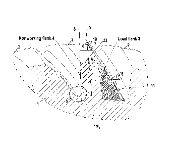
The invention relates to a bevel gear wheel (1) of a bevel gear unit, each
tooth (2) of which comprises a load flank (3)
and a non-working flank (4), wherein the teeth (2) have a helical or spiral
tooth trace, in particular a curved tooth longitudinal line,
and the teeth (2), in particular the upper meshing region of the teeth, have
an octoid tooth shape or a spherical involute tooth shape,
and the teeth have an excess material quantity (11) on the load flanks (4) in
order to reinforce the load flanks (4), in particular such
that the axis (9) that runs through the tooth tip-bisecting point A1 of the
tooth tip transverse line (23) and through the midpoint of the
gear wheel exhibits asymmetry of the teeth (2). The invention further relates
to a method for producing a bevel gear wheel (1)
according to one of the preceding claims, in which the tooth geometry is
produced by a four-axis or multi-axis method, in particular
a five-axis method.


French Abstract

L'invention concerne une roue dentée conique (1) d'un engrenage conique, dont les dents (2) présentent chacune un flanc de charge (3) et un flanc arrière (4), les dents (2) présentant une ligne de flanc à denture inclinée ou à denture courbée, en particulier une ligne longitudinale de dent incurvée et les dents (2), en particulier la zone supérieure venant en prise des dents, présentant une forme de dent octoïde ou une forme de dent à développante sphérique et les dents présentant une quantité supplémentaire de matériau (11) sur les flancs de charge (4) pour le renforcement des flancs de charge (4), en particulier de façon que l'axe (9), qui passe par le point A1, divisant en deux le sommet de la dent, de la ligne transversale du sommet de la dent (23) et par le centre de la roue dentée, présente une asymétrie des dents (2). L'invention concerne également un procédé pour fabriquer une roue dentée conique (1) selon l'une des revendications précédentes, dans lequel la géométrie de dent est fabriquée par un procédé à quatre axes ou à plus de quatre axes, en particulier un procédé à cinq axes.

Claims

Note: Claims are shown in the official language in which they were submitted.


The embodiments of the invention in which an exclusive
property or privilege is claimed are defined as follows:
1. A bevel gear of a bevel gear unit whose teeth each
have a load flank and a nonworking flank, wherein
the teeth have a helical or spiral toothed trace, or a
curved tooth longitudinal line;
the teeth have an octoid tooth shape or a spherical
involute tooth shape;
the teeth include added material on the load flanks in
order to reinforce the load flanks; and
pressure angles of the tooth flanks along the teeth
are variable such that the pressure angles decrease by a
value in the range of 0° to 8°, from a tooth heel toward a
tooth toe.
2. The bevel gear according to claim 1, wherein the teeth
have a curved tooth longitudinal line.
3. The bevel gear according to claim 1 or 2, wherein the
teeth have an octoid tooth shape or a spherical involute
tooth shape in an upper meshing region of the teeth.
4. The bevel gear according to any one of claims 1 to 3,
wherein the teeth include added material on the load flanks
in order to reinforce the load flanks, so that an axis
running through a tooth-tip-bisecting point of a tooth-tip
transverse line and through a center of the toothed gear
reveals an asymmetry of the teeth.
5. The bevel gear according to any one of claims 1 to 4,
wherein the pressure angles of the tooth flanks along the
teeth are variable such that the pressure angles decrease
-10-

by a value in the range of 0° to 8°, from the tooth heel
toward the tooth toe.
6. The bevel gear according to any one of claims 1 to 5,
wherein the pressure angles of the tooth flanks along the
teeth are variable such that the pressure angles decrease
by a value of 5°, from the tooth heel toward the tooth toe.
7. The bevel gear according to any one of claims 1 to 6,
wherein the pressure angles of the load flank are 25° to
45°.
8. The bevel gear according to any one of claims 1 to 7,
wherein the pressure angles of the load flank are 30° to
40°.
9. The bevel gear according to any one of claims 1 to 8,
wherein the added material is in a lower or inner region of
the load flank.
10. The bevel gear according to any one of claims 1 to 9,
wherein the added material is within the lower two-thirds
or the lower three-fourths of the load flank.
11. The bevel gear according to any one of claims 1 to 10,
wherein a tangent at any given point of the load flank is
flatter than a corresponding tangent of the nonworking
flank, and the tangent therefore encloses a greater angle
with the radial tooth axis than on the nonworking flank.
12. The bevel gear according to any one of claims 1 to 10,
wherein a tangent at any given point of a pitch and rolling
circle of the load flank is flatter than a corresponding
tangent of the nonworking flank, and the tangent therefore
-11-

encloses a greater angle with the radial tooth axis than on
the nonworking flank.
13. The bevel gear according to any one of claims 1 to 12,
wherein the toothed gear has a modulus in the range of 3 mm
to 30 mm.
14. The bevel gear according to any one of claims 1 to 13,
wherein a tooth tip has a boundary modification at a tooth
toe so as to ensure a tooth tip thickness greater than 0.3
times module.
15. The bevel gear according to any one of claims 1 to 13,
wherein a tooth tip has a boundary modification being a
variable tip rounding along a tooth-tip longitudinal line
or a tip shortening at a tooth toe so as to ensure a tooth
tip thickness greater than 0.3 times module.
-12-

Description

Note: Descriptions are shown in the official language in which they were submitted.


CA 02793260 2012-09-14
Transl. of W02011/147582
LOAD-OPTIMIZED BEVEL-GEAR TEETH
The invention relates to a toothed gear of a bevel gear
unit whose teeth each have a load flank and a nonworking flank, and
to a method of making it.
The design of the tooth geometry of bevel gears is
generally effected symmetrically relative to an axis of symmetry
that runs through the gear center and radially through the tooth.
This is justified on the basis that toothed gears are generally
designed and produced to operate equally in both directions
(forward and backward).
Depending on the direction of operation, an individual
tooth during the transmission of torque has a load flank that is
engaged and transmits the torque to the load flank of the opposing
tooth, and a nonworking flank. When the toothed gear rotates, the
nonworking flank of a tooth comes into contact either partially or
not at all with the following opposing tooth of the meshing toothed
gear so long as there is no reversal in the direction of rotation.
In practice, bevel gear units often do not require any
reversal of the direction of rotation. Nevertheless, the flanks of
the individual teeth of a toothed gear are produced identically and
further machined for both rotational directions.
There are a variety of approaches for increasing the
maximum possible transmission of force for a gear. One approach is
to have the surface undergo heat treatment in order to prevent
damage to the tooth flanks. Damage to tooth flanks occurs, for
example, in response to excessively high contact pressures. To
- 1 -

CA 02793260 2016-09-22
avoid this, manufacture of the tooth geometry is, among other
approaches, followed by finishing the surface, i.e. subjecting
it to surface treatment or hardening it. In other approaches,
the tooth shape is optimized and its basic rack profile is
standardized by DIN 867.
An object of this invention is to optimize a bevel gear
of the type referenced above so as to improve its load rating
and to enable increased torque to be transmitted by the bevel
gear.
The present invention provides an approach wherein the
teeth first of all include a helical or spiral tooth trace, in
particular a curved tooth longitudinal line, and wherein
second the teeth, in particular the top region of the engaging
teeth have an octoid tooth shape or a spherical involute tooth
shape, and wherein third the teeth include added material on
the load flanks in order to reinforce the load flanks.
According to an aspect of the present invention, there is
provided a bevel gear of a bevel gear unit whose teeth each
have a load flank and a nonworking flank, wherein
the teeth have a helical or spiral toothed trace, or a
curved tooth longitudinal line;
the teeth have an octoid tooth shape or a spherical
involute tooth shape;
the teeth include added material on the load flanks in
order to reinforce the load flanks; and
pressure angles of the tooth flanks along the teeth are
variable, such that the pressure angles decrease by a value in
the range of 0 to 8 , from a tooth heel toward a tooth toe.
According to another aspect of the present invention,
there is provided a method of making a bevel gear as described
herein, wherein the tooth geometry is fabricated by a four-
axis or multiaxis method.
In a preferred embodiment of the invention, the teeth include
added material on the load flanks in order to reinforce the load
flanks so that the axis running through the tooth-tip-bisecting
- 2 -

CA 02793260 2016-09-22
point of the tooth-tip transverse line and through the center
of the toothed gear reveals an asymmetry of the teeth.
The tooth-tip transverse line is formed by the section of
the cutting plane that is perpendicular to the rotational axis
of the toothed gear and of the tooth surface (tooth tip
surface) of the toothed gear that is radially the most outward.
According to the invention, the teeth include added
material on the load flanks to reinforce the load flanks. Added
material refers here to the presence of tooth material that is
present only on one side of the axis of symmetry when the tooth
is viewed symmetrically. The radial tooth axis runs first of all
- 2a -

CA 02793260 2012-09-14
Transl. of W02011/147582
through a point that is located on the tooth-tip transverse line
and that divides the tooth-tip transverse line into two equal
parts, and secondly through the center of the toothed gear.
This added material is disposed in the lower or inner
region of the load flank, in particular inside the lower two thirds
or the lower three quarters of the load flank.
It is in particular advantageous if the tangent on any
given point of the load flank, in particular on the pitch circle
and rolling circle, is flatter than the corresponding tangent in
the nonworking flank. The tangent on the load side thus encloses
an angle (8) with the radial tooth axis that is greater than that
of the nonworking flank.
The advantageous of this type of asymmetrical tooth
profile is an increase in torque transmission that by enlarging the
radii of curvature of the load flank results in a reduction in
flank contract pressure. As a result, the risk of damaging the
tooth, in particular the flank region, is reduced.
The invention furthermore makes it possible to implement
variability in the pressure angle on the load side along the tooth-
tip longitudinal line. Selecting a larger pressure angle at the
tooth heel relative to the tooth toe enables the angular range to
be enlarged. As a result, the risk of teeth becoming sharper is
counteracted, especially in the toe region. The pressure angles
along the tooth flanks can be implemented so as to be variable such
that the pressure angles from the tooth heel toward the tooth toe
decrease by an amount in the range of 00 to 8 , in particular to 5 .
- 3 -

CA 02793260 2012-09-14
Transl. of W02011/147582
It is preferably recommended that the pressure angles be
implemented as large as possible so that the pressure angle (a) of
the load flank measures 25 to 45 , preferably 300 to 400
.
Publications DE 10 2005 016746 and JP 09032908 also show
asymmetrical tooth shapes. These include added material on the
nonworking flank, unlike the present invention. This finds
application primarily in hypoid gear teeth where different tooth
shapes result from an axial offset. Added material on the
nonworking flank does not result in any increase in the flank load
rating, and in some cases can even lead to a decrease. For
practical reasons this is implemented in hypoid gears so as to
compensate for different sliding and engagement relationships
between load flank and nonworking flank.
Whereas current traditional production methods limit the
degree of freedom for production and are optimized with the aim of
producing multiple teeth of a toothed gear simultaneously, a high-
precision production of a toothed gear using a milling or grinding
machine, the die of which is guided on four or more axes, can
enable a more individualized shaping of the teeth to be
implemented.
This also has freedom in fabricating the tooth profile
shape. Aside from an octoid shape in which the line of action
corresponds to an approximate straight line, a spherical involute
tooth shape can be produced that contributes to an improved
insensitivity to displacement.
- 4 -

ak 02793260 2012-09-14
Transl. of W02011/147582
These bevel gears can be employed especially
advantageously in large-scale gear units, such as for example used
in rudder/propeller propulsion units.
Embodiments of the invention are shown in the drawing and
described below in more detail.
FIG. 1 is a view of the tooth with axis of symmetry and
added material;
FIG. 2 is a view of the tooth along the tooth flank
including different pressure angles;
FIG. 3 is a sectional view through the tooth profile with
small modifications relative to the basic rack profile in the
pressure angles at the tooth heel and tooth toe;
FIG. 4 is sectional view through the tooth profile with
large modifications relative to the basic rack profile in the
pressure angles at the tooth heel and tooth toe;
FIG. 1 shows a bevel gear 1 that has multiple teeth 2
distributed around its circumference, each of which has a load
flank 3 and a nonworking flank 4. The load flank 3 and the
nonworking flank 4 of two adjacent teeth 2 are connected by a tooth
root region 5, also called the "bottom land."
Since a preferred direction of rotation is intended for
the transmission of torque, the load flanks 3 and the nonworking
flanks 4 have different functions that are determined by a
differing geometry.
The load flank 3 serves for torque transmission during
normal operation and is designed with a large pressure angle a 6.
Pressure angles a of the load flank 3 here measure 25 to 45 ,
- 5 -

CA 02793260 2012-09-14
Transl. of W02011/147582
preferably 300 to 40 . The nonworking flank 4 is designed with
smaller pressure angles. Due to a flatter tangent 7 at any given
point along the load flank 3, illustrated here on the pitch circle
or rolling circle, relative to a corresponding tangent 8 of the
nonworking flank 4, the tooth has an asymmetrical shape.
Due to the asymmetrical geometry, this new tooth shape
lacks the typical tooth center line, such as found in conventional
symmetrical teeth. This is replaced by a "radial tooth axis" 9
that runs through a gear center M1 and tooth-tip-bisecting point Al.
Tooth-tip-bisecting point Al divides tooth-tip transverse line 23
into two parts of equal size. The respective tangents at the load
flank and nonworking flank each enclose angles 8 10 of different
size with this radial tooth axis. The tangent 8 of the nonworking
flank 4 is steeper than the tangent 7 of the load flank 3. As a
result, the tangent 7 of the load flank 3 encloses a greater angle
8 10 with the radial tooth axis 9 than does the tangent 8 of the
nonworking flank 4 with the radial tooth axis 9.
If this radial tooth axis 9 is used to compare the load
flank 3 and the nonworking flank 4, additional added material 11
becomes evident on the side of the load flank 3. Here the added
material 11 increases significantly in the lower or inner region of
the tooth, that is, toward the tooth root region 5. The added
material 11 of the load flank 3 varies as a function of the tooth
geometry and the pressure angle a 6, and can be indicated by a
factor f within a numerical range greater than 1.0 to 1.5.
FIG. 2 shows one shape, by way of example, of a tooth 2
along a tooth width 12 from a tooth heel 13 toward a tooth toe 14.
- 6 -

CA 02793260 2012-09-14
Transl. of W02011/147582
Due to the designed shape of the toothing with its curved tooth
longitudinal line, a tooth length 15 here is greater than the tooth
width 12. The drawing shows that the pressure angles a 6 at one
tooth flank of the tooth heel 13 (pressure angle oche., 16) can be
different than at the tooth toe 14 (pressure angle athe 17). The
region of the tooth flank between the tooth heel 13 and the tooth
toe 14 thus has a variable pressure angles a 6 along the tooth
length 15 that become smaller along the tooth flank from the tooth
heel 13 toward the tooth toe 14. The values of the difference here
for pressure angles 6 from the tooth heel 16 to the tooth toe 17
range from 00 to 8 , preferably around 50. The tangent at the tooth
heel 13 is thus flatter relative to the tangent at the tooth toe 14
and thus encloses a greater angle 8
heel 18 than pto. 19 at the tooth
toe.
FIG. 3 shows an optimized tooth shape 20 with added
material 11. The added material 11 is in the lower or inner region
of the load flank 3. The amount of added material 11 on the load
side 3 is relatively low compared with the amount of material for
the entire tooth. This is due to the difference between the
pressure angles of a standard basic rack profile 21 and the
optimized tooth shape 20. The pressure angle a 6 in the standard
basic rack profile 21 on the load flank 3 at a. = 20 is identical
on the nonworking flank 4 at a. = 20 . The pressure angle a 6 of
the optimized tooth shape 20 on the load flank 3 at a. = 25 is
different on the nonworking flank 4 at a. = 25 .
FIG. 3 essentially shows the optimized tooth shape 20 of
the teeth 2 in an embodiment with a spherical involute shape. This
- 7 -

CA 02793260 2016-09-22
embodiment cannot be produced with the proposed tooth geometry
using traditional fabrication processes such as hobbing and
shaving. The optimized tooth shape can, however, be fabricated by
a four-axis, in particular by a multiaxis method, in particular a
five-axis method. Only in this way can the tool perform with high
precision the three-dimensional removal of material that is
required for the optimized tooth shape 20 of the teeth 2. The
fabrication methods, in particular here are grinding and/or
milling.
FIG. 4 shows another development of the tooth flank that
has a significantly greater amount of added material 11 than shown
in FIG. 3. This is due to the greater difference between the
pressure angles of the standard basic rack profile 21 and the
optimized tooth shape 20. The pressure angle a 6 in the standard
basic rack profile 21 on the load flank 3 at a. = 20 is identical
on the nonworking flank 4 at a. = 20 . The pressure angle a 6 of
the optimized tooth shape 20 on the load flank 3 at a. = 35 is
different on the nonworking flank 4 at a. = 18.5 . FIG. 4 shows
here that the tip thickness of a tooth tip 22 can become smaller as
pressure angle a 6 increases. The FIG. here compares optimized
tooth shape 20 with the tooth tip of standard basic rack profile
21. FIG. 4 also shows optimized tooth shape 20 of teeth 2 with a
spherical involute shape on the load side 3 of the tooth 2.
An unillustrated variant has large pressure angles that are
so large that it is necessary to perform boundary modification
in the region of the tooth tip. This is intended to prevent a
full hardening that can generally occur below a tooth
- 8 -

CA 02793260 2012-09-14
Transl. of W02011/147582
thickness of 3.0 x m. This is critical in order to prevent damage
to the tooth tip. This type of boundary modification can be
performed as variable tip rounding along the tooth-tip longitudinal
line or as a conical tip shortening at the tooth toe.
Another unillustrated embodiment comprises placing added
material 11 inside the lower two-thirds or the lower three-fourths
of the load flank 3.
- 9 -

Representative Drawing
A single figure which represents the drawing illustrating the invention.
Administrative Status

2024-08-01:As part of the Next Generation Patents (NGP) transition, the Canadian Patents Database (CPD) now contains a more detailed Event History, which replicates the Event Log of our new back-office solution.

Please note that "Inactive:" events refers to events no longer in use in our new back-office solution.

For a clearer understanding of the status of the application/patent presented on this page, the site Disclaimer , as well as the definitions for Patent , Event History , Maintenance Fee  and Payment History  should be consulted.

Event History

Description Date
Time Limit for Reversal Expired 2020-08-31
Inactive: COVID 19 - Deadline extended 2020-08-19
Inactive: COVID 19 - Deadline extended 2020-08-06
Inactive: COVID 19 - Deadline extended 2020-07-16
Inactive: COVID 19 - Deadline extended 2020-07-02
Inactive: COVID 19 - Deadline extended 2020-06-10
Inactive: COVID 19 - Deadline extended 2020-05-28
Inactive: COVID 19 - Deadline extended 2020-05-14
Common Representative Appointed 2019-10-30
Letter Sent 2019-05-27
Grant by Issuance 2017-04-18
Inactive: Cover page published 2017-04-17
Inactive: Final fee received 2017-03-06
Pre-grant 2017-03-06
Notice of Allowance is Issued 2017-01-23
Letter Sent 2017-01-23
Notice of Allowance is Issued 2017-01-23
Inactive: Approved for allowance (AFA) 2017-01-16
Inactive: Q2 passed 2017-01-16
Amendment Received - Voluntary Amendment 2017-01-10
Amendment Received - Voluntary Amendment 2016-09-22
Inactive: S.30(2) Rules - Examiner requisition 2016-06-07
Inactive: Report - No QC 2016-06-07
Amendment Received - Voluntary Amendment 2015-11-20
Letter Sent 2015-06-19
Inactive: Adhoc Request Documented 2015-06-19
Amendment Received - Voluntary Amendment 2015-05-21
Request for Examination Received 2015-05-21
Request for Examination Requirements Determined Compliant 2015-05-21
All Requirements for Examination Determined Compliant 2015-05-21
Amendment Received - Voluntary Amendment 2015-01-09
Amendment Received - Voluntary Amendment 2014-11-07
Amendment Received - Voluntary Amendment 2014-09-17
Amendment Received - Voluntary Amendment 2014-04-14
Inactive: IPC assigned 2013-06-14
Inactive: Notice - National entry - No RFE 2013-05-28
Amendment Received - Voluntary Amendment 2013-03-20
Letter Sent 2013-01-28
Inactive: Single transfer 2013-01-10
Inactive: Cover page published 2012-12-28
Inactive: Acknowledgment of national entry correction 2012-12-13
Inactive: IPC assigned 2012-12-10
Inactive: First IPC assigned 2012-12-10
Inactive: IPC assigned 2012-12-10
Application Received - PCT 2012-11-07
Inactive: Notice - National entry - No RFE 2012-11-07
Inactive: Inventor deleted 2012-11-07
Correct Applicant Request Received 2012-09-17
National Entry Requirements Determined Compliant 2012-09-14
Application Published (Open to Public Inspection) 2011-12-01

Abandonment History

There is no abandonment history.

Maintenance Fee

The last payment was received on 2016-04-27

Note : If the full payment has not been received on or before the date indicated, a further fee may be required which may be one of the following

  • the reinstatement fee;
  • the late payment fee; or
  • additional fee to reverse deemed expiry.

Patent fees are adjusted on the 1st of January every year. The amounts above are the current amounts if received by December 31 of the current year.
Please refer to the CIPO Patent Fees web page to see all current fee amounts.

Fee History

Fee Type Anniversary Year Due Date Paid Date
Basic national fee - standard 2012-09-14
Registration of a document 2013-01-10
MF (application, 2nd anniv.) - standard 02 2013-05-27 2013-05-14
MF (application, 3rd anniv.) - standard 03 2014-05-27 2014-05-12
MF (application, 4th anniv.) - standard 04 2015-05-27 2015-05-07
Request for examination - standard 2015-05-21
MF (application, 5th anniv.) - standard 05 2016-05-27 2016-04-27
Final fee - standard 2017-03-06
MF (patent, 6th anniv.) - standard 2017-05-29 2017-04-25
MF (patent, 7th anniv.) - standard 2018-05-28 2018-05-02
Owners on Record

Note: Records showing the ownership history in alphabetical order.

Current Owners on Record
TECHNISCHE UNIVERSITAET DRESDEN
SCHOTTEL GMBH
Past Owners on Record
BERTHOLD SCHLECHT
BIRGIT HUTSCHENREITER
MICHAEL POTTS
MICHAEL SENF
STEFFEN SCHAEFER
Past Owners that do not appear in the "Owners on Record" listing will appear in other documentation within the application.
Documents

To view selected files, please enter reCAPTCHA code :


To view images, click a link in the Document Description column. To download the documents, select one or more checkboxes in the first column and then click the "Download Selected in PDF format (Zip Archive)" or the "Download Selected as Single PDF" button.

List of published and non-published patent-specific documents on the CPD .

If you have any difficulty accessing content, you can call the Client Service Centre at 1-866-997-1936 or send them an e-mail at CIPO Client Service Centre.


Document
Description 
Date
(yyyy-mm-dd) 
Number of pages   Size of Image (KB) 
Description 2012-09-13 9 308
Abstract 2012-09-13 2 111
Claims 2012-09-13 4 91
Drawings 2012-09-13 2 41
Representative drawing 2012-11-12 1 17
Description 2013-03-19 10 327
Claims 2013-03-19 4 126
Description 2016-09-21 10 331
Claims 2016-09-21 3 86
Representative drawing 2017-03-16 1 13
Abstract 2017-03-19 2 111
Notice of National Entry 2012-11-06 1 193
Reminder of maintenance fee due 2013-01-28 1 111
Courtesy - Certificate of registration (related document(s)) 2013-01-27 1 102
Notice of National Entry 2013-05-27 1 207
Acknowledgement of Request for Examination 2015-06-18 1 176
Commissioner's Notice - Application Found Allowable 2017-01-22 1 164
Maintenance Fee Notice 2019-07-07 1 183
Correspondence 2012-09-16 2 84
PCT 2012-09-13 1 36
Correspondence 2012-12-12 1 41
Amendment / response to report 2015-11-19 1 32
Examiner Requisition 2016-06-06 5 297
Amendment / response to report 2016-09-21 14 478
Amendment / response to report 2017-01-09 1 33
Final fee 2017-03-05 1 38