Note: Descriptions are shown in the official language in which they were submitted.
81625303
PIPETTE TIP TRAYS
Related Patent Applications
This patent application claims the benefit of U.S..provisional application No.
61/315,377, filed
March 18, 2010, entitled PIPETTE TIP TRAYS, naming Arta Motadel and Peter Paul
Blaszcak as
Inventors, and designated by Attorney Docket No. PEL-1014-PV. This patent
application also is
related to U.S. design patent application no. 29/357,908, filed March 18, 2010
(now U.S. design
patent no. D632,803, issued on February 15, 2011), entitled PIPETTE TIP TRAY
ASSEMBLY,
naming Arta Motadel and Peter Paul Blaszcak as inventors, and designated by
Attorney Docket
No. PEL-1014-DUS. This patent application also Is related to U.S. design
patent application no.
29/335,452, filed February 14, 2011, entitled PIPETTE TIP TRAY ASSEMBLY,
naming Ma
Motadel and Peter Paul Blaszcak as inventors, and designated by Attorney
Docket No. PEL-1014-
DUS2. This patent application also claims the benefit of U.S. provisional
patent application No
61/442,682, filed February 14, 2011, entitled PIPETTE TIP TRAYS, naming Arta
Motadel and
Peter Paul Blaszcak as inventors, and designated by Attorney Docket No. PEL-
1014-PV2.
Field
The technology relates In part to pipette tip trays for use in biotechnology
applications.
Background
Pipette tips are utilized In a variety of industries that have a requirement
for handling fluids, and are
used In facilities including medical laboratories and research laboratories,
for example. In many
instances pipette tips are used In large numbers, and often are utilized for
processing many
samples and/or adding many reagents to samples, for example.
Pipette tips often are substantially cone-shaped with an aperture at one end
that can engage a
dispensing device, and another relatively Smaller aperture at the other
end.that can receive and
emit fluid. Pipette tips generally are manufactured from a moldable Optic,
such as polypropylene,
for example. Pipette tips are made in a number of sizes to allow for accurate
and reproducible
liquid handling for volumes ranging from nanoliters to milliliters.
1
CA 2793396 2018-02-15
CA 02793396 2012-09-14
WO 2011/116230 PCT/US2011/028881
Pipette tips can be utilized in conjunction with a variety of dispensing
devices, including manual
dispensers (e.g., pipettors) and automated dispensers. A dispenser is a device
that, when
attached to the upper end of a pipette tip (the larger opening end), applies
negative pressure to
acquire fluids, and applies positive pressure to dispense fluids. The lower or
distal portion of a
dispenser (typically referred to as the barrel or nozzle) is placed in contact
with the upper end of
the pipette tip and held in place by pressing the barrel or nozzle of the
dispenser into the upper end
of the pipette tip. The combination then can be used to manipulate liquid
samples.
Pipette tips often are shipped, stored and presented to a user or dispenser in
trays. A tray often
includes a rack and a lid, where the rack includes a base and a plate. The
plate, or top, generally
includes bores through which pipette tips are inserted partially. A lid
sometimes is attached to a
rack by a hinge, and a user generally swings the lid open to access pipette
tips in the rack for use.
Summary
In some embodiments, provided are pipette tip trays that include: a lid
containing an edge and a
fastener component in association with the edge of the lid, and a rack in
effective connection with
the lid, which rack comprises a base that includes sides, a fastener component
in association with
the rack, and a top that contains an array of bores configured to receive
partially inserted pipette
tips; where: the fastener component in association with the edge of the lid is
releasably secured to
the fastener component in association with the rack, the fastener component in
association with
the edge of the lid is concealed within the rack, and the lid can pivot with
respect to the rack
around the fastener component in association with the edge of the lid. A
fastener component in
association with the rack is in association with a side of the base in some
embodiments. In certain
embodiments, one or more fastener components in association with the rack
(e.g., one or more
slots) is located on a short side of the rack, and in some embodiments, one or
more fastener
components in association with the rack (e.g., one or more slots) is located
on a long side of the
rack. In some embodiments, the fastener component in association with the rack
is in association
with a step in the rack base, and sometimes the step forms a lip around the
base perimeter. In
certain embodiments, the fastener component in association with the edge of
the lid is a projection
fastener component and the fastener component in association with the rack is
an orifice fastener
component. A projection fastener component sometimes is a tab, and an orifice
fastener at times
is a slot. In some embodiments, the fastener component in association with the
edge of the lid
2
CA 02793396 2012-09-14
WO 2011/116230 PCT/US2011/028881
associates with the fastener component in association with the rack in a
slidable fit, reversible fit,
snap fit, interference fit or combination thereof. In some embodiments,
provided are methods that
include: providing a pipette tip tray described herein and disengaging the lid
from the rack.
In certain embodiments, provided are pipette tip trays that include: a top
containing an array of
bores, each bore configured to receive a partially-inserted pipette tip; a
base having sides, one or
more of the sides including a step and a first fastener in association with
the step; and a lid that
includes a second fastener, where: the first fastener and the second fastener
independently are
selected from a fastener including a slot and a fastener comprising a tab, the
tab is in flexible
association with the lid or side, and the first fastener and the second
fastener are reversibly
engaged. The side in association with the fastener sometimes comprises at
least one slot. In
some embodiments, the lid comprises at least one tab, and sometimes the tab is
in flexible
association with the edge of the lid. The lid at times comprises a top and
sides, and an edge of
one of the sides is in association with the tab. The side in association with
the fastener sometimes
comprises two slots and the lid comprises two tabs. In some embodiments, the
lid comprises a slot
and a tab and the side in association with the fastener includes a slot and a
tab. In certain
embodiments, the step defines a lip, and sometimes the lip comprises the first
fastener. The first
fastener sometimes is a slot, and at times the lip comprises two or more
slots. In some
embodiments, engagement of the first fastener with the second fastener
conceals the tab. In some
embodiments, provided are methods that include: providing a pipette tip tray
of any one of the
embodiments described herein; and disengaging the first fastener from the
second fastener,
thereby disengaging the lid from the side that includes the first fastener. In
some embodiments a
side including the step and a first fastener in association with the step is
located on a long side of
the tray. In certain embodiments a side including the step and a first
fastener in association with
the step is located on a short side of the tray.
In some embodiments, provided are pipette tip trays that include: a top
containing an array of
bores, each bore configured to receive a partially-inserted pipette tip; and a
base having sides,
each side including an edge in association with a surface of the top, where:
the edge of each of
two or more of the sides of a base includes a plurality of first fasteners,
the surface of the top
includes a plurality of second fasteners, and the first fasteners are
releasably secured to the
second fasteners. In some embodiments, the first fasteners and the second
fasteners
independently are selected from orifices and projections. The projections at
times snap-fit with the
orifices. In some embodiments, the orifices comprise a slot, and sometimes,
the orifices comprise
3
CA 02793396 2012-09-14
WO 2011/116230 PCT/US2011/028881
walls and wall termini. The projections sometimes comprise a barb configured
to engage a contact
point of a wall, wall terminus or wall and wall terminus of an orifice. In
some embodiments, the wall
or wall terminus is an external wall or wall terminus and in certain
embodiments, the wall or wall
terminus is an internal wall or wall terminus. Each projection can comprise
two or more barbs. In
some embodiments, a projection comprises two, three, four, five, six or more
barbs. In certain
embodiments, the top is in reversible association with the sides, and
sometimes, the top is not
irreversibly fixed to one or more of the sides. The top is not welded to one
or more of the sides in
some embodiments, and the surface of the top at times comprises the
projections. An edge of
each of the two or more sides comprises the orifices in some embodiments. In
certain
embodiments, two or more internal walls or wall termini comprise the orifices.
The surface of the
top sometimes comprises projections and orifices and at times the edge of each
of the two or more
sides comprise orifices and projections. The surface of the top sometimes
comprises projections
and at times the orifices comprise two or more internal wall or wall termini.
In certain
embodiments, provided also are methods that include: providing a pipette tip
tray of any one of the
embodiments described herein, and disengaging the first fasteners from the
second fasteners,
thereby disengaging the top from the side(s) of the base.
In certain embodiments, provided are pipette tip trays that include: a top
containing an array of
bores, each bore configured to receive a partially-inserted pipette tip; a
base having sides, one or
more sides including a step and a first fastener in association with the step;
and a lid that includes
a second fastener, where: the first fastener and the second fastener
independently are selected
from a fastener that includes a slot and a fastener including a tab, the tab
is in flexible association
with the lid or side, the first fastener and the second fastener are
reversibly engaged, the edge of
each of two or more of the sides includes a plurality of third fasteners, the
surface of the top
includes a plurality of fourth fasteners, and the third fasteners are
releasably secured to the fourth
fasteners. In some embodiments, the third fasteners and the fourth fasteners
independently are
selected from orifices and projections. The projections sometimes snap-fit
with the orifices, and at
times the orifices comprise a slot. In some embodiments, the orifices comprise
walls and wall
termini, and the projections comprise barbs configured to engage contact
points in the walls, wall
termini or walls and wall termini of the orifices. Each projection comprises
two barbs in some
embodiments, and in certain embodiments, each projection comprises more than 2
barbs. In some
embodiments each projection comprises 4 barbs. The top sometimes is in
reversible association
with the sides, and in certain embodiments, the top is not irreversibly fixed
to one or more of the
sides. The top is not welded to one or more of the sides in some embodiments,
and the surface of
4
CA 02793396 2012-09-14
WO 2011/116230 PCT/US2011/028881
the top sometimes comprises the projections. In certain embodiments, the edge
of each of the two
or more sides comprises the orifices. In some embodiments, two or more
internal walls or wall
termini comprise the orifice. The surface of the top sometimes comprises
projections and orifices
and at times the edge of each of the two or more sides comprise orifices and
projections. The
surface of the top sometimes comprises projections and at times the orifices
comprise two or more
internal wall or wall termini. The side sometimes includes at least one slot,
and in some
embodiments, the lid comprises at least one tab. A tab sometimes is in
flexible association with
the edge of the lid, and in certain embodiments, the lid comprises a top and
sides, and an edge of
one of the sides is in association with the tab. The side comprises two slots
and the lid comprises
two tabs in some embodiments, and in certain embodiments, the lid comprises a
slot and a tab and
the side includes a slot and a tab. The step at times defines a lip, and
sometimes the lip extends
around the perimeter of the sides. In some embodiments, the lip comprises the
first fastener, and
sometimes the first fastener is a slot. The lip can include two or more slots
in some embodiments,
and sometimes engagement of the first fastener with the second fastener
conceals the tab. In
certain embodiments, provided also are methods that include: providing a
pipette tip tray of any
one of the embodiments described herein, and disengaging the first fasteners
from the second
fasteners, thereby disengaging the top from the side(s). Also, in certain
embodiments, provided
are methods that include: providing a pipette tip tray of any one of the
embodiments described
herein, and disengaging the third fasteners from the fourth fasteners, thereby
disengaging the top
from the side(s). In some embodiments a side including the step and a first
fastener in association
with the step is located on a long side of the tray. In certain embodiments a
side including the step
and a first fastener in association with the step is located on a short side
of the tray.
In certain embodiments, a pipette tip tray or rack includes pipette tips
partially inserted in the bores,
or subset of the bores, and sometimes a pipette tip tray or rack contains no
pipette tips. A surface
of the top sometimes comprises a tube coaxially and concentrically disposed
with each bore. In
certain embodiments, each tube includes an interior surface that comprises a
step configured to
provide a seating surface for a seating feature of a pipette tip partially
inserted in the bore.
Certain embodiments are described further in the following description,
examples, claims and
drawings.
5
81625303
According to an embodiment, there is provided a pipette tip tray, comprising:
a top
that includes an array of bores, each bore configured to receive a partially-
inserted
pipette tip; and sides, each side comprising an edge in association with a
surface of
the top, wherein: the edge of each of the sides includes one or more of a
plurality of
first fasteners, the surface of the top includes a plurality of second
fasteners, wherein
the first fasteners and the second fasteners independently are selected from
orifices
and projections which snap-fit together, and the first fasteners are
releasably secured
to the second fasteners, wherein each first fastener is secured to one second
fastener.
According to another embodiment, there is provided a method, comprising:
providing
a pipette tip tray as described herein, and disengaging the first fasteners
from the
second fasteners, thereby disengaging the top from the sides.
5a
CA 2793396 2018-02-15
81625303
Brief Description of the Drawinos
The drawings illustrate embodinients of the technology and are not limiting.
For clarity and ease of
illustration, the drawings are not made to scale and, in some instanced,
various aspects May be
shown exaggerated or enlarged to facilitate an understanding of particular
embodiments.
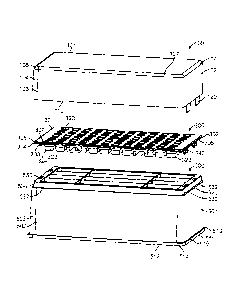
FIG 1 shows an exploded view of a pipette tip tray, and FIG 2 shows a
perspective view of a tray
base, FIG 3A shows a top view of a tray base, FIG 3B shows first side view of
a tray base, FIG 3C
shows a second side view of a tray base, and FIG 30 shows an expanded detail
view of a portion
of the tray base highlighted In FIG 3A.
FIG 4A shows a top view of a rack. FIG 48 shows a cross sectional view orthe
rack through section A-A
shown in FIG 4A, and FIG 4C shows an expanded detail view of a portion of the
rack shown in FIG 4B. FIG 5A Shows a top view of a tray with the lid In an
open position with
respect to the rack, FIG 5B shows a cross sectional view of the tray through
section A-A
shown in FIG 5A, and FIG 5C shows an expanded detail view of a portion of the
tray shown in FIG
5B. FIG 6A shows a cross section view of a pipette tip tray with a lid In a
closed position, FIG 63
shows an expanded detail view of a portion of the tray shown In FIG 6A, and
FIG 6C shows a
perspective view of an internal lid hinge embodiment FIG 7A shows a cross
section view of a
pipette tip tray with a lid in a closed position, and FIG 7B shows an expanded
detail view of
fasteners that i'eleasably secure a snap plate to a base.
FIG 8A shows a first cross sectional view of a rack through section B-B shown
in FIG 8B, FIG 8B
shows a top view of the rack, FIG 8C shows a second cross sectional view of a
rack through
section A-A shown in FIG 8B, and FIG 8D shows an expanded detail view of
fasteners that
release* secure a snap plate to a base.
F19 9 shows a perspective view of a lid, FIG 10A shows atop view of a lid, FIG
10B shows a first
side view of a lid and FIG 10C shows a second side view of a lid.
FIG 11A shows a top view of a snap plate, FIG 11B shows a first side view of a
snap plate, FIG
11C shows a second side view of a snap plate and FIG 11D shows an expanded
detail view of a
snap plate fastener. FIG 12 shows a perspective view of the bottom of a plate.
6
CA 2793396 2018-02-15
CA 02793396 2012-09-14
WO 2011/116230 PCT/US2011/028881
FIG 13 shows an exploded view of a pipette tip tray, and FIG 14 shows a
perspective view of a tray
base. FIG 15 shows a bottom view of a tray base. FIG 16 shows a side
perspective view of a
pipette tip tray with the lid in a closed position.
.. FIG 17A shows a cross section view of the tray taken along the line D-D
shown in FIG 16, and FIG
17B shows an enlarged view of detail region B shown in FIG 17A. FIG 18A shows
a top view of a
pipette tip tray with the lid in an open position, FIG 18B shows a cross
section view of the tray
taken along the line E-E shown in FIG 18A, and FIG 18C shows an enlarged view
of detail region
C shown in FIG 18B. FIG 19 shows a perspective view of a lid.
FIG 20A shows a top view of a tray base configured to receive a 4 barb
projection fastener, and
FIG 20B shows an enlarged perspective view of a 4 slot (e.g., X-slot, cross-
slot) fastener that forms
a releasable interference fit with a 4 barb (e.g., 4 prong) projection
fastener.
.. FIG 21A shows a side cross-section view of a tray base configured to
receive a 4 barb projection
fastener, and FIG 21B shows an enlarged perspective cross-section view of a 4
barb projection
fastener engaged in a 4 slot fastener receiver. The cross section in 21A is
taken along the midline
of a wall configured as a projection fastener receiver.
.. FIG 22A shows a front/rear view of a snap plate configured with 4 prong
projection fasteners, FIG
22B shows a side view of a snap plate configured with 4 prong projection
fasteners, and FIG 22C
shows an enlarged perspective view of a 4 prong projection fastener depending
from the bottom
surface of a snap plate embodiment.
.. Detailed Description
In certain embodiments, provided are pipette tip trays having one or more of
the following features:
(i) having an internal, concealed member between the lid and the rack about
which the lid can
pivot, and (ii) having snap plate fasteners configured to releasably secure a
snap plate to a base.
Such pipette tip trays confer multiple advantages. For example, trays that
include feature (i) can
require less plastic for manufacture and often are more compact than trays
having an external
hinge. These features can impart advantages in packing and shipping, for
example. Also, tray
embodiments that include fasteners that releasably secure the lid to the rack
in connection with
feature (i) can be utilized with or without a lid. Further, trays that include
feature (ii) can be
7
CA 02793396 2012-09-14
WO 2011/116230 PCT/US2011/028881
manufactured efficiently as the plate can be releasably secured to the rack
without energy and time
required for welding the two components together, for example. Fasteners
between the snap plate
and the base can be configured for disengagement of a snap plate from a base
for trays having
feature (ii), and separation can facilitate recycling materials. Other
advantageous features of the
.. technology are described hereafter.
Lid and Rack Engagement
A pipette tip tray generally includes a lid and a rack, and a rack includes a
top affixed to a base.
The top is referred to herein as a "plate" or "snap plate" from time to time,
as in some
embodiments, a top snaps into the base by engaging certain types of fasteners.
A lid and rack are in flexible association in certain embodiments. A lid can
pivot away from the
rack around fasteners that releasably secure the lid and rack in some
embodiments. In certain
embodiments, the lid pivots away from the rack around an edge of the lid and
an edge of the rack.
The rack and lid generally are in effective connection with one another.
Sometimes surfaces of the
lid and rack are in direct contact with one another when the lid is in an open
or partially open
position, and in some embodiments, surfaces of the lid and rack are in
proximity to one another
when the lid is in an open or partially open position (e.g., surfaces of the
lid and rack and in indirect
contact and are connected via fastener components in the lid and rack). One
side of the lid and
one side of the rack often are in effective connection with one another when
the lid is in an open or
partially open position, and the two elements sometimes are associated by one
or more fasteners.
A fastener often is an assembly that includes two or more fastener components.
A fastener
component individually is referred to herein also as a "fastener."
Fasteners in the lid and rack can interact in any convenient arrangement,
including without
limitation, a slip fit, interference fit, snap fit, locked engagement,
removable engagement, reversible
engagement, releasable engagement and combinations thereof (e.g., locked
engagement and
reversible engagement). Any suitable fasteners in the lid and rack can be
selected, such as
projection-orifice fasteners (e.g., male-female fasteners), for example. Non-
limiting examples of
projection fasteners include tabs, pins, pegs, barbs, hooks, prongs and the
like. A fastener can
have any suitable profile, including without limitation, S-shape, J-shape, l-
shape, W-shape, cross
or X-shape and Y-shape profiles and the like. A projection fastener sometimes
can include one or
more terminal projections configured to effect an interference fit or snap-fit
(e.g., barb, node, boss
8
CA 02793396 2012-09-14
WO 2011/116230 PCT/US2011/028881
and the like), in some embodiments. A projection fastener can include a region
of decreased
thickness, and/or a region of increased thickness, and sometimes flexes in an
area of decreased
thickness. Non-limiting examples of orifice fasteners include apertures,
slots, holes, bores,
indentations, cross or X-shapes and the like, and projection fastener
components generally are
configured to mate with a counterpart orifice fastener.
A fastener can be in connection with any suitable portion of the lid (e.g.,
lid edge 110) and base
(e.g., lip). A fastener can be in association with an edge of a lid when the
fastener is directly
connected to the lid edge or is connected near the lid edge and in proximity
to the edge. A
fastener can be in association with a rack, and/or in association with a base
side. A fastener in
association with the rack can be located on or in a structure of the base
(e.g., edge, step, lip), and
can be located on or in a plate or top in certain embodiments. In some
embodiments, a lid can be
in effective connection with a short side of a rack having a rectangular top.
In certain
embodiments, a lid can be in effective connection with a long side of a rack
having a rectangular
top.
A fastener can be constructed from any suitable material for flexible
arrangement between the lid
and rack. A fastener sometimes is constructed from a moldable material and
sometimes a polymer
(e.g., plastic, thermoplastic). Non-limiting examples of moldable materials
include polypropylene
(PP), polyethylene (PE), high-density polyethylene (HDPE), low-density
polyethylene (LDPE),
polyethylene teraphthalate (PET), polyvinyl chloride (PVC),
polytetrafluoroethylene (PTFE),
polystyrene (PS), high-density polystyrene, acrylnitrile butadiene styrene
copolymers, crossl inked
polysiloxanes, polyurethanes, (meth)acrylate-based polymers, cellulose and
cellulose derivatives,
polycarbonates, ABS, tetrafluoroethylene polymers, corresponding copolymers,
plastics with higher
flow and lower viscosity or a combination of two or more of the foregoing, and
the like. A fastener
can be constructed from the same material, or different material, as the tray
element to which the
fastener is connected. In some embodiments, a fastener component is
constructed from a material
different than the material from which its fastener component counterpart is
manufactured. A
fastener sometimes is manufactured from two or more materials in some
embodiments. A lid and
a rack are connected by fasteners not configured as an external hinge, in
certain tray
embodiments. A lid and rack sometimes are connected by fasteners configured as
an internal
hinge in some embodiments (e.g., FIG 4C for closed position and FIG 50 for
open position).
9
CA 02793396 2012-09-14
WO 2011/116230 PCT/US2011/028881
When projection-orifice fasteners are connected, a portion of, or all of, the
projection fastener often
is concealed (e.g., substantially concealed, partially concealed, partially
inserted). In some
embodiments, a tab in association with the lid can be concealed within a slot
in association with the
base. A projection fastener can include a flexible feature in some
embodiments. A flexible feature
sometimes is a seam, indentation, region of thinner thickness, junction and
the like. In certain
embodiments, a junction between the lid and a tab serves as a flexible joint
feature (e.g., hinge
feature).
Any suitable number of projection fasteners and orifice fasteners may be
utilized. In certain
embodiments about Ito about 100 fasteners can be utilized (e.g., about 2, 3,
4, 5, 6, 7, 8, 9, 10,
20, 30, 40, 50, 60, 70, 80, 90). The number of projection fasteners is equal
to or fewer than the
number of orifice fasteners in certain embodiments. In some embodiments, a
tray has fewer tabs
than slots, and sometimes there are slots on each short side of a rack and a
lid having tabs can be
mounted to either side of the rack. In certain embodiments, the slots are on
each long side of a
rack and a lid having tabs can be mounted to either long side of the rack. In
some embodiments,
the slots are on each short side of a rack and a lid having tabs can be
mounted to either short side
of the rack.
Top and Base Engagement
A top (or plate) generally includes an array of bores, where each bore in the
array generally is
configured to receive a pipette tip. An array can have any useful number of
bores, which
sometimes is a multiple of 96 bores (e.g., 192, 288, 384, 576, 672, 768 or
1536). An array can be
any suitable two-dimensional array, such as an X by Y array of bores, where X
independently is
about 2 to about 1,000 bores and Y independently is about 2 to about 1,000
bores (e.g., an 8 by 12
array; 16 by 24 array). An array of bores often includes a regularly spaced
set of bores, where the
longitudinal axis extending through each bore is spaced equally from other
longitudinal axes (e.g.,
center-to-center distance of about 9 millimeters for 96 bore plates). In
embodiments where a rack
includes one or more pipette tips, the pipette tips often are inserted
partially into bores of the array.
In the latter embodiments, portions of a pipette tip typically reside above
the plate, are co-extensive
with the thickness of the plate, and reside below the plate within the body of
the rack. A pipette tip
often includes a step that determines the amount of the pipette tip above the
plate in embodiments
where a pipette tip is inserted partially, and rests, in a bore within the
plate.
CA 02793396 2012-09-14
WO 2011/116230 PCT/US2011/028881
Any suitable fasteners can be utilized, and any convenient number of
fasteners, can be utilized to
connect a top and base. A top and base can be releasably secured (e.g.,
permanent, semi-
permanent engagement), where a significant amount of force is required to
separate the elements
after connection. The elements sometimes are reversibly connected, and can be
separated by a
separation force greater than a threshold force. In some embodiments, the
releasably secured
connection is sufficient for retaining the top to the base during shipping and
normal use, thereby
obviating one or more welds between the two elements (e.g., no sonic weld,
adhesive weld). In
some embodiments, a tray includes one or more welds (e.g., spot welds,
continuous welds)
between the top and base.
Fasteners utilized to connect the top and base sometimes form an interference
fit. In some
embodiments, projection fasteners include one or more barbs that form an
interference fit with
flexible features in orifice fasteners (e.g., 1 or more, 2 or more, 3 or more,
4 or more, 5 or more, 6
or more, 8 or more, or 10 or more). An example of an interference fit fastener
combination is
illustrated in FIGS 7B, 8C, 8D, 11C, 11D, and 12. The fasteners illustrated in
FIGS 7B, 8C, 8D,
11C, 11D, and 12 can have any suitable number of barbs and can be used to
attach a tray top to a
tray base for any suitable application (e.g., pipette tip tray rack, test tube
rack, microcentrifuge tube
rack, the like or combinations thereof). An example of a 4 barb fastener
embodiment is shown in
FIGS 20A ¨ 22C.
Examples of Pipette Tip Tray Features
Certain non-limiting pipette tip tray features for particular tray embodiments
are shown in the
drawings. The figures show tray embodiments that include 96 bores configured
to receive pipette
tips, and it is understood that the number of bores can be readily altered
(e.g., trays having 192,
288, 384, 576, 672, 768 or 1536 bores). It is also understood that certain
fastener features
described herein can engage a snap-plate with a base in pipette tray and tube
rack embodiments.
FIGS 1 and 13 show an exploded view of a pipette tip tray embodiment, having a
lid 100, atop
(plate) 300 and a base 500. The top 300 and base 500 in combination form a
rack 70, and the
rack 70 and lid 100 in combination form a tray 50.
Also shown in lid 100 of FIGS 1 and 13 are top 101, shorter side 102, longer
side 103, rounded
corner 104 between sides 102 and 103, and rounded edge 105 between shorter,
rounded edge
11
81625303
106 and longer rounded, edge 107. Also shown is bottom edge 110 and tabs 120
in association
with the bottom edge.
As shown In plate 300 In FIGS 1 and 13 are top surface 301, shorter edge 302,
longer edge 303,
and shorter edge to longer edge junction 304. Also shown is shorter top
surface to edge transition
306, longer top surface to edge transition 307 and rounded transition 305
between these elements.
Plate 300 in FIGS 1 and 13 also illustrate bores 320, and tubes 323 having
tube members 322 and
324. Plate 300 shown in FIGS 1 and 13 also Includes fasteners 340 that can
releasably secure
plate 300 to base 500 in a rack assembly 70.
Base embodiment 500 shown in FIGS 1 and 13 includes shorter side 501, longer
side 502, and
rounded comer503 between sides 501 and 502. Shown also is foot 510 that
Includes surface 516
that forms a rim around the base, shorter edge 511, longer edge 512 and
rounded corner 514 between
edges 511 and 512. Also shown are step 520, which forms a lip around the base
perimeter, and
slot fasteners 522, configured to receive the tab fasteners 120 of the lid.
Base embodiment 500
shown In FIGS 1 and 13 also Includes relieved shorter surface 530 (e.g.,
offset from side 501),
relieved longer surface 532 (e.g., offset from side 602) and rounded corner
534 between surfaces
530 and 532. Also included in base 500 are slot fasteners 550 configured to
receive projection
fasteners 340 of plate 300.
FIG 2 shows a perspective view of a tray base. Shown are top surface 536,
rounded edge
transitions 531, 535 and 533 between the top surface 536 and relieved surfaces
530, 532 and 534,
respectively. Also shown are Inner wall surface 538 and Inner surface 539 of
rounded corner 503.
FIG 2 also Illustrate rib members 540, perpendicular rib members 542 and rib
junctions 544, whloh
are cylindrical in certain embodiments.
FIG 3A shows a top view of a tray base 500 with dimples 561 on bottom surface
560, FIG 3B
shows first side view of a tray base, FIG 3C shows a second side view of a
tray base, and FIG 3D
shows an expanded detail view of a portion of the tray base highlighted in FIG
3A. FIG 30 shows
.. angled, Inner surfaces (e.g., beveled surfaces) 524, 526 and 528 of slot
fasteners 522, and angled
Inner surfaces (e.g., beveled surfaces) 552 of slot fastener 650.
FIG 4A shows a top view of a tray, FIG 4B shows a cross sectional view of tray
500 through
section A-A shown in FIG 4A, and FIG 4C shows an expanded detail view of a
portion of the tray
12
CA 2793396 2018-02-15
81625303
shown in FIG 4B. FIG 4C shows engagement of tab fastener 120 of the lid with
slot fastener 622
of the base where the lid Is In a closed position with respect to the rack,
and Illustrates edge
surface 125 of edge 110 of the lid, tab connector 126,. tab outer surface 121,
tab inner surface 123
and tab body 122.
FIGS 5A and 18A show a top view of a tray 50 with a lid In an open position
with respect to the
rack, FIGS 58 and 188 show a gross sectional view of the tray through section
A-A
shown in FIG 5A and through section E-E shown In FIG 18A. FIGS 5C and 18C show
an expanded
detail view of a portion of the tray shown in FIGS 5B and 18B. Shown In FIGS
5C and 18C are tab
connector 126 in a flexed position, surface 530 of the base, angled inner
surface 528 withirrsiot
522 (e.g., angled with respect to side 501) terminating at point 528A In
contact with tab body 122,
angled inner surface 524 (e.g., angled with respectto side 501) terminating at
point 524A in
contact with tab body 122, and step 529 of the base that terminates at point
529A, which also Is In
contact with the tab body. Contact points 524A, 528A and 529A secure the
position of tab body
122 and allow lid 100 to pivot around tab connector 126 when the lid is opened
into an open
position with respect to the rack. A rack fastener can provide any suitable
number of contact
points for securing a lid fastener, and sometimes a lid fastener is sectked by
1, 2, 3, 4, 5, 6, 7, or 9
contact points or contact surfaces within a rack fastener. A rack fastener
configured to engage a
lid fastener can include one or more angled surfaces (e.g., 1, 2, 3, 4, 5, 6,
7 or 8 angled surfaces),
and the angle of each surface independently is selected from an angle of about
5 degrees to about
85 degrees with respect to a wall surface (e.g., 530, 501).
FIGS 6A and 17A show across Section view of a pipette tip tray with a lid in a
closed position,
FIGS 6B and 17B show an expanded detail view of a portion of the tray shown In
FIGS 6A and
17A. FIG 6C shows a perspective view o'f an internal lid hinge embodiment
Shown in FIG 6A,
FIG 17A or FIGS 6A and FIG 17A are pipette tip containment section walls 566,
containment
section wall interior surfaces 567, containment section wall to Containment
section bottom rounded
corner 560, interior containment section bottom surface 562:dimple 569 and
containment section
Interior void 568. FIGS 68 and 173 show tab body surface 121 and opposite tab
body surface
123, and tab body terminal bevels 128 and 129. Such bevels can facilitate
connection of tabs 120
with slots 522. Also shown Is containment section connector rib 570.
13
CA 2793396 2018-02-15
=
81625303
FIG 7A shows a cross section view of a pipettelip tray with a lid in a closed
position, and FIG 7B
shows an expanded detail view of fasteners that releasably secure a snap plate
to a base. FIG 7A
shows containment section to rack wall connector rib 571 having cross section
thickness 566. FIG
7B shows plate fastener 340 engaged with base fastener 550, and angled inner
surface 555, plate'
fastener contact surface 554, and thickness 553 within base fastener 560. A
rack fastener
configured lo engage a plate fastener can include one or more angled surfaces
(e.g., 1, 2, 3, 4, 5,
6, 7 or 8 angled surfaces), and the angle of each surface independently is
selected from an angle
of about 5 degrees to about 85 degrees with respect to a wall surface (e.g.,
530, .601). Also shown
in FIG 78 are fastener body 341, barb 344 and spacer, 342 of plate fastener
340. In certain
16 embodiments, barb 344 deflects surface 554 of slot 550 away from Its
resting p98it1on as the plate
fastener is engaged with the base fastener, and surface 554 relaxes back to
Its resting position on
edge 346 of fastener 340 when the fastener 340 is fully engaged with slot 550
and barb 344 is
positioned past the terminus 555A of slot 550.
16 FIG EA shows a first cross sectional view of rack 70 through section B-B
shown in FIG 8B, FIG 8B
shows a top view of a rack, FIG 8C shows a second cross sectional view of a
rack through section
A-A shown in FIG 8B, and FIG 8D shows an expanded detail view of fasteners
configured to
releasably secure a snap plate with a base. A description above regarding
engagement of base
fastener 550 and plate fastene 340 with respect to FIG 7B is applicable to FIG
8C.
FIGS 9 and 19 show a perspective view of the interior of a lid, with interior
counterparts 101A,
102A, 103A, 105A and 107A of exterior surface features 101, 102, 103, 105 and
107, respectively,
are shown. Certain features of tab 120 also areshown, including terminal edge
127, angled side
128, non-angled side 129 and tab body 128A.
FIG 10A shows a top view of a lid, FIG 10B shows a first side view of a lid
and FIG 10C shows a
second side view of a lid. FIG 10C illustrates by hatches in tab 120 a beveled
surface 129A that
demarks an increase of thickness from the tab connection region 120A to tab
body 128A. In
certain embodiments, tabs 120 can be located on the long edge of the lid, as
Illustrated In FIG 19,
or the short edge of the lid.
FIG. 11A st)ows a top view of a snap plate, which illustrates an internal,
annular step 320A and.
dimple 329. FIG 11B shows a first side view of a snap plate, FIG 11C shows a
second side view of
a snap plate,and FIG 110 shows an expanded detail view of a snap plate
fastener. In certain
14
CA 2793396 2018-02-15
CA 02793396 2012-09-14
WO 2011/116230 PCT/US2011/028881
embodiments, the surface of one or more tube members 324 includes an annular
region of
increased thickness.
FIG 12 shows a perspective view of a bottom of a plate. Shown in FIG 12 is
bottom surface 301A
opposite top surface 301. Also shown are tubes 323 that project from bottom
surface 301. Tubes
323 are stepped, and have tube member 324 in connection with bottom surface
301A and
concentric, co-axially arranged tube member 322 extending from tube member
324. At the
junction of tube members 322 and 324 is step 324A, and the thickness 322A at
the terminus of
tube member 322 is shown, defining the perimeter and of bore 320. In some
embodiments, tube
member 322 can include an annular boss, which has an increased thickness, of
any suitable profile
(e.g., rounded, flat). Such a boss can be present on any suitable number of
tubes (e.g., alternating
tubes in the array) and can be located at about position 323A on a tube. A
tube can be defined by
any bore length to bore diameter ratio useful for retaining pipette tips,
where bore length is the
longitudinal axis distance from the top surface of the plate to the terminus
of a tube and bore
diameter is measured at the top surface of the plate. In some embodiments, the
ratio is about 0.5
to about 3.0 (e.g., about 0.75, 1.0, 1.5, 2.0, 2.5). The position of step
324A, which defines the
position of step 323, along the longitudinal axis distance from the bottom
surface of the plate to the
tube terminus, is suitable for retaining pipette tips. In certain embodiments,
step 324A is located
about one-fifth to about four-fifths of the distance from the bottom surface
of the plate to the tube
terminus. In certain embodiments, a outer surface of a tube is not stepped,
and sometimes the
outer surface of a tube is substantially smooth. A tube often includes a
feature in the tube interior
for retaining a pipette tip, including a step, bevel and the like.
Base embodiment 500' shown in FIG 20A illustrates an alternative 4 slot
fastener 550' configured
to receive alternative 4 prong or barb projection fasteners 340' (see FIGS 21
and 22) of plate 300'.
Plate 300' can be configured to hold larger pipette tips (e.g., 1000
microliter or larger) and/or tubes
of various sizes (e.g., microcentrifuge tubes, 5 ml tubes, 15 ml tubes, the
like or combinations
thereof). Slot fastener 550' is formed at the junction 544' of two internal
walls or ribs 540' of base
500'. Slot fastener 550' substantially resembles two of slot fastener 550
joined together in an X or
cross formation, as shown in FIG 20B. Base fastener 550', also includes angled
inner surface
555', and plate fastener contact surface 554'. Base embodiment 500' also is
configured to
engage a plate projection fastener and can include one or more angled surfaces
(e.g., 1, 2, 3, 4, 5,
6, 7 or 8 angled surfaces), and the angle of each surface independently is
selected from an angle
of about 5 degrees to about 85 degrees with respect to a wall surface. In some
embodiments, slot
81625303
fastener positions are chosen to correspond to the internal wall junctions
closest to the corners of
base 500' external walls. The prime designation, "''', indicates the
designated structure is
substantially similar to a structure shown in another drawing bearing the same
numerical identifier.
Illustrated in FIG 21A is a cross section side view of rack base 500' with an
attached 4 prong
fastener snap plate 300'. FIG 218 is an enlarged perspective, detail view of
the engagement of
snap plate 300' and rack base 500'. Shown in FIG 21B are fastener body 341',
barb 344' and
spacer 342' of plate fastener 340'. In certain embodiments, barb 344' deflects
surface 554' of slot
550' away from its resting position as the plate fastener is engaged with the
base fastener, and
surface 554' relaxes back to its resting position on edge 346' of fastener
340' when the fastener
340' is fully engaged with slot 550' and barb 344' is positioned past the
terminus 555A' of slot
550'.
Front/rear and side views of 4 barb fastener 340' snap plate 300 are
illustrated in FIGS 22A and
22B. Also illustrated in FIGS 22A and 22B are snap plate upper surface 301'
and lower 301A', from
which fastener 340' depends. FIG 22A also shows a detail area that is enlarged
in FIG 22C. FIG.
22C shows an enlarged view of the various surfaces of 4 prong fastener 340'
Moldable Materials
Each tray component can be manufactured from a commercially suitable material.
Tray
components often are manufactured from one or more moldable materials,
independently selected
from those that include, without limitation, polypropylene (PP), polyethylene
(PE), high-density
polyethylene (HDPE), low-density polyethylene (LDPE), polyethylene
teraphthalate (PET),
polyvinyl chloride (PVC), polytetrafluoroethylene (PTFE), polystyrene (PS),
high-density
polystyrene, acrylnitrile butadiene styrene copolymers, crosslinked
polysiloxanes, polyurethanes,
(meth)acrylate-based polymers, cellulose and cellulose derivatives,
polycarbonates, ABS,
tetrafluoroethylene polymers, corresponding copolymers, plastics with higher
flow and lower
viscosity or a combination of two or more of the foregoing, and the like.
Non-limiting examples of plastics with higher flow and lower viscosity
include, any suitable material
having a hardness characterized by one or more of the following properties, in
certain
embodiments: a melt flow rate (230 degrees Celsius at 2.16 kg) of about 30 to
about 75 grams per
10 minutes using an ASTM D 1238 test method; a tensile strength at yield of
about 3900 to about
16
CA 2793396 2018-02-15
CA 02793396 2012-09-14
WO 2011/116230 PCT/US2011/028881
5000 pounds per square inch using an ASTM D 638 test method; a tensile
elongation at yield of
about 7 to about 14% using an ASTM D 638 test method; a flexural modulus at 1%
sectant of
about 110,000 to about 240,000 pounds per square inch using an ASTM D 790 test
method; a
notched Izod impact strength (23 degrees Celsius) of about 0.4 to about 4.0
foot pounds per inch
using an ASTM D 256 test method; and/or a heat deflection temperature (at
0.455 MPa) of about
160 degrees to about 250 degrees Fahrenheit using an ASTM D 648 test method. A
material used
to construct the distal section and/or axial projections include moldable
materials in some
embodiments. Non-limiting examples of materials that can be used to
manufacture the distal
section and/or axial projections include polypropylene, polystyrene,
polyethylene, polycarbonate,
and the like, and mixtures thereof. In certain embodiments, a tray component
described herein is
not manufactured from an elastomer, with certain exceptions for antistatic
components described
hereafter should they be included.
Anti-Microbial Materials
A tray component may include one or more antimicrobial materials. An
antimicrobial material may
be coated on a surface (e.g., inner and/or outer surface) or impregnated in a
moldable material, in
some embodiments. One or more portions or sections, or all portions and
sections, of a tray
component may include one or more antimicrobial materials. In some embodiments
anti-microbial
agents or substances may be added to the moldable plastic during the
manufacture process. In
some embodiments, the anti-microbial agent or substance can be an anti-
microbial metal. The
addition of anti-microbial agents may be useful in (i) decreasing the amount
of microbes present in
or on a device, (ii) decreasing the probability that microbes reside in or on
a device, and/or (iii)
decreasing the probability that microbes form a biofilm in or on a device, for
example.
Antimicrobial materials include, without limitation, metals, halogenated
hydrocarbons, quaternary
salts and sulfur compounds.
Non-limiting examples of metals with anti-microbial properties are silver,
gold, platinum, palladium,
copper, iridium (i.e. the noble metals), tin, antimony, bismuth, zinc cadmium,
chromium, and
thallium. The afore-mentioned metal ions are believed to exert their effects
by disrupting
respiration and electron transport systems upon absorption into bacterial or
fungal cells. A
commercially accessible form of silver that can be utilized in devices
described herein is
SMARTSILVER NovaResin. SMARTSILVER NovaResin is a brand of antimicrobial
master batch
additives designed for use in a wide range of polymer application. Billions of
silver nanoparticles
17
CA 02793396 2012-09-14
WO 2011/116230 PCT/US2011/028881
can easily be impregnated into PET, PP, PE and nylon using standard extrusion
or injection
molding equipment. SMARTSILVER NovaResin additives may be delivered as
concentrated
silver-containing master batch pellets to facilitate handling and processing.
NovaResin is designed
to provide optimum productivity in a wide range of processes, including fiber
extrusion, injection
.. molding, film extrusion and foaming.
Further non-limiting examples of anti-microbial substances or agents include,
without limitation,
inorganic particles such as barium sulfate, calcium sulfate, strontium
sulfate, titanium oxide,
aluminum oxide, silicon oxide, zeolites, mica, talcum, and kaolin. Anti-
microbial substances also
include halogenated hydrocarbons, quaternary salts and sulfur active
compounds.
Halogenated hydrocarbons, include, without limitation, halogenated derivatives
of salicylanilides
(e.g., 5-bromo-salicylanilide; 4',5-dibromo-salicylanilide; 3,4',5-tribromo-
salicylanilide; 6-chloro-
salicylanilide; 4'5-dichloro-salicylanilide; 3,4'5-trichloro-salicylanilide;
4',5-diiodo-salicylanilide;
3,4',5-triiodo-salicylanilide; 5-chloro-3'-trifluoromethyl-salicylanilide; 5-
chloro-2'-trifluoromethyl-
salicylanilide; 3,5-dibromo-3'-trifluoromethyl-salicylanilide; 3-chloro-4-
bromo-4'-trifluoromethyl-
salicylanilide; 2',5-dichloro-3-phenyl-salicylanilide; 3',5-dichloro-4'-methyl-
3-phenyl-salicylanilide;
3',5-dichloro-4'-phenyl-3-phenyl-salicylanilide; 3,3',5-trichloro-6'-(p-
chlorophenoxy)-salicylanilide;
3',5-dichloro-5'-(p-bromophenoxy)-salicylanilide; 3,5-dichloro-6'-phenoxy-
salicylanilide; 3,5-
dichloro-6'-(o-chlorophenoxy)-salicylanilide; 5-chloro-6'-(o-chlorophenoxy)-
salicylanilide; 5-chloro-
6'-beta-naphthyloxy-salicylanilide; 5-chloro-6'-alpha-na phthyloxy-
salicylanilide; 3,3',4-trichloro-5,6'-
beta-naphthyloxy-salicylalide and the like).
Halogenated hydrocarbons also can include, without limitation, carbanilides
(e.g., 3,4,4'-trichloro-
carbanilide (TR1CLOCARBAN); 3,3',4-trichloro derivatives; 3-trifluoromethy1-
4,4'-dichlorocarbanilide
and the like). Halogenated hydrocarbons include also, without limitation,
bisphenols (e.g., 2,2'-
methylenebis(4-chlorophenol); 2,2'-methylenebis(4,5-dichlorophenol); 2,2'-
methylenebis(3,4,6-
trichlorophenol); 2,2'-thiobis(4,6-dichlorophenol); 2,2'-diketobis(4-
bromophenol); 2,2'-
methylenebis(4-chloro-6-isopropylphenol); 2,2'-isopropylidenebis(6-sec-butyl-4-
chlorophenol) and
the like).
Also included within hydrogenated hydrocarbons are halogenated mono-and poly-
alkyl and aralkyl
phenols (e.g., methyl-p-chlorophenol; ethyl-p-chlorophenol; n-propyl-p-
chlorophenol; n-butyl-p-
chlorophenol; n-amyl-p-chlorophenol; sec-amyl-p-chlorophenol; n-hexyl-p-
chlorophenol;
18
CA 02793396 2012-09-14
WO 2011/116230 PCT/US2011/028881
cyclohexyl-p-chlorophenol; n-heptyl-p- chlorophenol; n-octyl-p-chlorophenol; o-
chlorophenol;
methyl-o-chlorophenol; ethyl-o-chlorophenol; n-propyl-o-chlorophenol; n-butyl-
o-chlorophenol; n-
amyl-o-chlorophenol; tert-amyl-o-chlorophenol; n-hexyl-o-chlorophenol; n-
heptyl-o-chlorophenol; p-
chlorophenol; o- benzyl-p-chlorophenol; o-benzyl-m-methyl-p-chlorophenol; o-
benzyl-m, m-
di methyl-p- chlorophenol; o-phenylethyl-p-chlorophenol ; o-phenylethyl-m-
methyl-p-chlorophenol ;
3- methyl-p-chlorophenol; 3,5-dimethyl-p-chlorophenol; 6-ethyl-3-methyl-p-
chlorophenol; 6-n-
propy1-3-methyl-p-chlorophenol; 6-iso-propy1-3-methyl-p-chlorophenol; 2-ethyl-
3, 5-dimethyl-p-
chlorophenol; 6-sec butyl-3-methyl-p-chlorophenol; 6-diethylmethy1-3-methyl-p-
chlorophenol; 6-
iso-propy1-2-ethy1-3-methyl-p-chlorophenol; 2-sec amyl-3, 5-di methyl-p-
chlorophenol; 2-
diethylmethy1-3, 5-dimethyl-p-chlorophenol; 6-sec octy1-3-methyl-p-
chlorophenol; p-bromophenol;
methyl-p-brdmophenol; ethyl-p-bromophenol; n-propyl-p- bromophenol; n-butyl-p-
bromophenol; n-
amyl-p-bromophenol; sec-amyl-p-bromophenol; n- hexyl-p-bromophenol; cyclohexyl-
p-
bromophenol; o-bromophenol; tert-amyl-o-bromophenol; n-hexyl-o-bromophenol; n-
propyl-m, m-
dimethyl-o-bromophenol; 2-phenyl phenol; 4-chloro- 2-methyl phenol; 4-chloro-3-
methyl phenol; 4-
chloro-3, 5-dimethyl phenol; 2, 4-dichloro-3, 5- dimethylphenol; 3,4, 5, 6-
terabromo-2-
methylphenol; 5-methyl-2-pentylphenol; 4-isopropyl-3- methylphenol; 5-chloro-2-
hydroxydiphenylemethane).
Halogenated hydrocarbons also include, without limitation, chlorinated phenols
(e.g.,
parachlorometaxylenol, p-chloro-o-benzylphenol and dichlorophenol); cresols
(e.g., p-chloro-m-
cresol), pyrocatechol; p-chlorothymol; hexachlorophene; tetrachlorophene;
dichlorophene; 2,3-
dihydroxy-5,5'-dichlorophenyl sulfide; 2,2'-dihydroxy-3,3',5,5'-
tetrachlorodiphenyl sulfide; 2,2'-
dihydroxy-3,3',5,5',6,6'-hexachlorodiphenyl sulfide and 3,3'-dibromo-5,5'-
dichloro-2,2'-
dihydroxydiphenylamine). Halogenated hydrocarbons also may include, without
limitation,
resorcinol derivatives (e.g., p-chlorobenzyl-resorcinol; 5-chloro-2, 4-
dihydroxy-di-phenyl methane;
4'-chloro-2, 4-dihydroxydiphenyl methane; 5-bromo-2,4- dihydroxydiphenyl
methane; 4'-bromo-2,
4-dihydroxydiphenyl methane), diphenyl ethers, anilides of thiophene
carboxylic acids,
chlorhexidines, and the like.
Quaternary salts include, without limitation, ammonium compounds that include
alkyl ammonium,
pyridinum, and isoquinolinium salts (e.g., 2,2'-methylenebis(4-chlorophenol);
2,2'-methylenebis(4,5-
dichlorophenol); 2,2'-methylenebis(3,4,6-trichlorophenol); 2,2'-thiobis(4,6-
dichlorophenol); 2,2'-
diketobis(4-bromophenol); 2,2'-methylenebis(4-chloro-6-isopropylphenol); 2,2'-
isopropylidenebis(6-
sec-buty1-4-chlorophenol); cetyl pyridinium chloride;
diisobutylphenoxyethoxyethyldimethylbenzyl
19
81625303
ammonium chloride; N-methyl-N- (2- hydroxyethyl)-N-(2-hydroxydodecy1)-N-benzyl
ammonium
chloride; cetyl trimethylamirionium bromide; stearyl trimethylsmmonlum
bromide; olpyl
dimethylethylammonium bromide; lauryldimethyichlorethoxyethylammonium
chloride;
lauryldimethylbenzyl-ammonium chloride; alkyl (Cg-C1g) dlmethyl (3, 4-
dichlorobenzy1)-animonium
chloride; lauryl pyridinium bromide; lauryi Iso-quinolinium bromide; N
(lauroyloxyethylaminoformylmethyl) pyridinium chloride, and the like).
Sulfur active compounds include, without limitation, thluram sulfides and
dithiocarbamates, for
example (e.g., disodium ethylene bis-dithiocarbamate (Nabam); diammonium
ethylene bis-
dithiocarbamate (amabam); Zn ethylene bis-dithiocarbamate (ziram); Fe ethylene
bis-
dithiocarbamate (ferbam); Mn ethylene bis-dithiocarbamate (manzate);
tetramrethyl thluram
disulfide; tetrabenzyl thiuram disulfide; tetraethyl thluram disulfide;
tetramethyl thiuram sulfide, and
= the like).
15' In certain embodiments, an antimicrobial material comprises one or more
df 4',5-
dibromosalicylanilide; 3,41,5-tribromosalicylanilide; 3,4',5-
trichlorosalicylanillde; 3,4,4'-
trIchlorocarbanilide; 3-triftuoromethy14,4'-dichlorocarbanilide; 2,2'-
methylenebis(3,4,6-
trichlorophenol); 2,4,4'richloro-2'-hydroxydiphenyl ether; Tyrothricin; N-
methyl-N-(2-hydroxyethyi-
N-(2-hydroxydodecy1)-N-benzylammonium chloride; cetyl pyridinium chloride;
2,3',5-
tribromosallcylanilide; chlorohexIdine dlgtuconate; chlorohexidine diacetate;
4',5-
dibromosailoylanifide; 3,4,44richlorocarbanilide; 2,4,44rIchloro-2-
hydrxixydlphenyl ether
(TRICLOSAN; 5-chloro-2-(2,4-dichlorophenoxy)phenol); 2,2'-dihydroxy-5, 5'-
dibromo-diphenyl
ether) and the like.
Methods for manufacturing anti-microbial containing plastic devices are
described in International
Patent Application No. PCT/US2009/047541, tied on June 16, 2009, published as
published
patent application no. WO 2010/008737 on January 21, 2010, and entitled
ANTIMICROBIAL
FLUID HANDLING DEVICES AND METHODS OF MANUFACTURE, having attorney docket
number PEL-1004-PC.
20
CA 2793396 2018-02-15
CA 02793396 2012-09-14
WO 2011/116230 PCT/US2011/028881
Degradable Materials
One or more pipette tip tray components described herein may be constructed
from a degradable
material. Any suitable degradable material may be utilized, including without
limitation from a
natural polymer, a bacterial produced cellulose, and/or chemically synthesized
polymeric material.
Non-limiting examples of a natural polymer include starch/synthetic
biodegradable plastic, cellulose
acetate, chitosan/cellulose/starch and denatured starch. Non-starch
biodegradable components
may include chitin, casein, sodium (or zinc, calcium, magnesium, potassium)
phosphate and metal
salt of hydrogen phosphate or dihydrogen phosphate, amide derivatives of
erucamide and
oleamide and the like, for example. Non-limiting examples of bacterial
produced cellulose include
homopolymers, polymer blends, aliphatic polyesters, chemosynthetic compounds
and the like.
Non-limiting examples of chemically synthesized polymeric material include
aliphatic polyester, an
aliphatic-aromatic polyester and a sulfonated aliphatic-aromatic polyester.
In some embodiments, a tray component is manufactured from a moldable material
that is
photodegradable and further includes a photosensitizer. Non-limiting examples
of photsensitizers
include aliphatic and/or aromatic ketones, including without limitation
acetophenone, acetoin,
acetonaphthone, 2'-acetonaphtone, anisoin, anthrone, bianthrone, benzil,
benzoin, benzoin methyl
ether, benzoin isopropyl ether, 1-decalone, 2-decalone, benzophenone, p-
chlorobenzophenone,
dibenzalacetone, benzoylacetone, benzylacetone, deoxybenzoin, 2,4-
dimethylbenzophenone, 2,5-
dimethylbenzophenone, 3,4-dimethylbenzophenone, 4-benzoylbiphenyl,
butyrophenone, 9-
fluorenone, 4,4-bis-(dimethylamino)-benzophenone, 4-dimethylaminobenzophenone,
dibenzyl
ketone, 4-methylbenzophenone, propiophenone, benzanthrone, 1-tetralone, 2-
tetralone,
valerophenone, 4-nitrobenzophenone, di-n-hexyl ketone, isophorone, xanthone
and the like.
Aromatic ketones may be used such as benzophenone, benzoin, anthrone,
deoxyanisoin and
quinones (e.g., anthraquinone, 1-aminoanthraquinone, 2-aminoanthraquinone, 1-
chloroanthraquinone, 2-chloroanthraquinone, 1-methylanthraquinone, 2-
methylanthraquinone, 1-
nitroanthraquinone, 2-phenylanthraquinone, 1,2-naphthoquinone, 1,4-
naphthoquinone, 2-methyl-
1,4-naphthoquinone, 1,2-benzanthraquinone, 2,3-benzanthraquinone,
phenanthrenequinone, 1-
methoxyanthraquinone, 1,5-dichloroanthraquinone, and 2,2'-dimethy1-1,11-
dianthraquinone, and
anthraquinone dyes. Quinones that may be used are 2-methylanthraquinone, 2-
chloroanthraquinone, 2-ethylanthraquinone and the like). A photodegradable
plastic may include
21
CA 02793396 2012-09-14
WO 2011/116230 PCT/US2011/028881
iron, zinc, cerium cobalt, chromium, copper, vanadium and/or manganese
compounds in certain
embodiments.
In some embodiments, a tray component comprises a polyhydroxy-containing
carboxylate, such as
polyethylene glycol stearate, sorbitol palmitate, adduct of sorbitol anhydride
laurate with ethylene
oxide and the like; epoxidized soybean oil, oleic acid, stearic acid, and
epoxy acetyl castor oil or
combinations thereof. A tray component may include maleic anhydride,
methacrylic anhydride or
maleimide in some embodiments, and in certain embodiments, a tray component
may comprise a
polymer attacking agent such as a microorganism or an enzyme. In some
embodiments, a tray
component may include a coating layer, which prevents passage of gas or
permeation of water, on
one or more surfaces that come into contact with a liquid. A tray component
that includes a
coating layer also may have silicon, oxygen, carbon, hydrogen, an edible oil,
a drying oil,
melamine, a phenolic resin, a polyester resin, an epoxy resin, a terpene
resin, a urea-
formaldehyde rein, a styrene polymer, polyvinyl chloride, polyvinyl alcohol,
polyvinyl acetate, a
polyacrylate, a polyamide, hydroxypropylmethylcellulose, methocel,
polyethylene glycol, an acrylic,
an acrylic copolymer, polyurethane, polylactic acid, a polyhydroxybutyrate-
hydroxyvalerate
copolymer, a starch, soybean protein, a wax, and/or mixtures thereof.
A tray component can be manufactured from any type of environmentally
friendly, earth friendly,
biologically friendly, natural, organic, carbon based, basic, fundamental,
elemental material.
Biologically or environmentally friendly materials can comprise any materials
that are considered to
inflict minimal or no harm on biological organisms or the environment. Such
materials can aid in
degradation and/or recycling of a tray or component thereof. Such materials
can have non-toxic
properties, aid in producing less pollutants, promote an organic environment,
and further support
living organisms. In some embodiments a tray component can be made from
recycled or organic
materials and/or in combination with degradable materials. In certain
embodiments, bio-PET can
be produced from a wide variety of different sources. Bio-PET can be produced
from any of type
of plant such as algae, for example. Other biologically or environmentally
friendly PET materials
may be produced from other sources such as animals, inert substances, organic
materials or man-
made materials, for example.
Degradable materials and methods of use are described in International Patent
Application No.
PCT/U52009/063762, filed on November 9, 2009, and entitled DEGRADABLE FLUID
HANDLING
22
81625303
DEVICES, having attorney docket number PEL-1005-PC .
Anti-Static Materials and Components
6
Anti-static materials and conditions sometimes are applied to a pipette tray
and/or component
thereof. In certain embodiments an anti-static agent can be incorporated into
a moldable plastic
during the manufacture process of a tray component described herein. A tray
component may
comprise any type of electrically conductive material, such as a conductive
metal for example.
Non-limiting examples of electrically conductive metals include platinum (Pt),
palladium (Pd),
copper (Cu), nickel (Ni), sliver (Ag) and gold (Au). A conductive metal may be
in any form in or on
a tray component, for example, such as metal flakes, metal powder, metal
strands or coating of
metal.
An electrically conductive material, or portion thereof, may be any material
that contains movable
electric charges, such as carbon for example. In some embodiments, a tray
component comprises
about 5% to about 40% or more carbon by weight (e.g., 7-10%, 9-12%, 11-14%, 13-
16%, 15-18%;
17-20%, 19-22%, 21-24%, 23-26%, 25-28%, 27-30%, 29-32%, 32-34%, 33-36%, or 35-
38%
carbon by weight).
A tray component that contacts a pipette tip can be a candidate for receiving
one or more
conductive materials, in some embodiments. Thus, in some embodiments, a plate
sometimes is
manufactured from a material that comprises one or more conductive materials.
A lid in certain
embodiments comprises a conductive material. A tray component also may include
a conductive
element, such as a conductive tab. A conductive element can be affixed to a
part of a tray
component, and sometimes Is In effective communication with another tray
component. For
,example, a conductive element, such as a conductive tab, may traverse a slot
or groove in a lid,
plate, base or combination thereof, and be In communication with the tray
exterior and tray interior.
Such a configuration can transmit electrostatic charge from pipette tips In
the tray Interior to the
tray exterior from which the charge can be discharged.
=
Pipette tips are substantially immobilized in certain antistatic tray
component embodiments, as
minimizing pipette tip movement may reduce the amount of static charge
generated in or on a
pipette tip. Pipette tips can be substantially immobilized 'by restricting
pipette tip movement in a
23
CA 2793396 2018-02-15
81625303
plate, for example. Elements in a plate can restrict movement, such as longer
bore length (e.g.,
longer tube length), smaller bore diameter and combinations thereof, for
example.. Elements in a
lid also can restrict movement, Such as placing the Inner surface of the lid
top In effective contact
with tops of pipette tips, for example. The Inner surface of the lid top is in
direct contact with tops
of the pipette tips In some embodiments, and a member In connection with the
lid that exerts
pressure on the pipette tip tops sometimes is present in a tray. In the latter
embodiments, the
member In connection with the'lld sometimes comprises a material that can
deform against the
pipette tip tops, suCh as an elastomeric material,õfor example. In some
embodiments a member in
connection with the lid sometimes comprises a conductive material. A member in
connection with
the lid sometimes is a pillow structure, that includes a casing containing a
conductive materiaLl
within which Is a material that can deform. A member In connection with the
lid Sometimes is in
effective connection with a conductive member In cornmunication with the tray
exterior (e.g., a tab
that traverses the lid, plate and/or base).
15. Methods for manufacturing components and trays comprising an anti-
static member are described
in International Patent Application No. PCT/US2010/021838, filed,on January
22, 2010; and
entitled "ANTI-STATIC PIPE i t E TIP TRAYS", having attorney docket number
PEL-1009-PC.
Methods for Manufacturing Tray Components
Tray components may be manufactured by any suitable process. Examples of
manufacturing
processes include thermoforming, vacuum forming, pressure forming, plug-assist
forming, reverse-
draw thermoforming, matched die forming, extrusion, casting and Injection
molding.
injection molding is a manufacturing process for producing objects (e.g., tray
components, for
example) from thermoplastic (e.g., nylon, polypropylene, polyethylene,
polystyrene and the like, for
example) and thermosetting plastic (e.g., epoxy and phenolics, for example)
materials. The plastic
material of choice often is fed into a heated barrel, mixed, and forced into a
mold cavity where it
cools and hardens to the configuration of the mold cavity. The melted material
sometimes Is
forced or Injected Into the mold cavity, through openings (e.g., a spree),
under pressure. A
pressure injection method ensures the complete filling of the mold with the
melted plastic. After the
mold cools, the mold portions are separated, and the molded object is
ejected.. In some
embodiments, additional additives can be included in the plastic or mold to
give the final product
24
CA 2793396 2018-02-15
CA 02793396 2012-09-14
WO 2011/116230 PCT/US2011/028881
additional properties (e.g., anti-microbial, or anti-static properties, for
example). In some
embodiments, tray components described herein are injection molded as a
unitary construct.
A mold often is configured to hold the molten plastic in the correct geometry
to yield the desired
product upon cooling of the plastic. Injection molds sometimes are made of two
or more parts.
Molds typically are designed so that the molded part reliably remains on the
ejector side of the
mold after the mold opens, after cooling. The part can then fall freely away
from the mold when
ejected from ejector side of the mold. In some embodiments, an ejector sleeve
pushes the tray
component from the ejector side of the mold.
Also provided herein is a mold for manufacturing a device by an injection mold
process, which
comprises a body that forms an exterior portion of the device and a member
that forms an inner
surface of the device.
Examples of Pipette Tip Tray Embodiments
Provided hereafter are certain non-limiting examples of embodiments of the
technology.
Al. A pipette tip tray, comprising:
a top that includes an array of bores, each bore configured to receive a
partially-inserted
pipette tip;
sides, one or more sides including a step and a first fastener in association
with the step;
and
a lid that includes a second fastener, wherein:
the first fastener and the second fastener independently are chosen from a
fastener
comprising a slot and a fastener comprising a tab,
the tab is in flexible association with the lid or side, and
the first fastener and the second fastener are reversibly engaged.
A2. The pipette tip tray of embodiment Al, wherein the side comprises at least
one slot.
A3. The pipette tip tray of embodiment Al or A2, wherein the lid comprises at
least one tab.
CA 02793396 2012-09-14
WO 2011/116230 PCT/US2011/028881
A4. The pipette tip tray of embodiment A3, wherein the tab is in flexible
association with the edge
of the lid.
A5. The pipette tip tray of embodiment A4, wherein the lid comprises a top and
sides, and an edge
of one of the sides is in association with the tab.
A6. The pipette tip tray of any one of embodiments Al to A5, wherein the side
comprises two slots
and the lid comprises two tabs.
A7. The pipette tip tray of any one of embodiments Al to A5, wherein the lid
comprises a slot and
a tab and the side includes a slot and a tab.
A8. The pipette tip tray of any one of embodiments Al to A7, wherein the step
defines a lip.
A9. The pipette tip tray of embodiment A8, wherein the lip comprises the first
fastener.
A10. The pipette tip tray of embodiment A9, wherein the first fastener is a
slot.
All. The pipette tip tray of embodiment A10, wherein the lip comprises two or
more slots.
Al2. The pipette tip tray of any one of embodiments Al to Al 1, whereby
engagement of the first
fastener with the second fastener conceals the tab.
A13. The pipette tip tray of any one of embodiments Al to Al2, wherein a side
including the step
and a first fastener in association with the step is located on a long side of
the tray.
A14. The pipette tip tray of any one of embodiments Al to Al2, wherein a side
including the step
and a first fastener in association with the step is located on a short side
of the tray.
B1. A pipette tip tray, comprising:
a top that includes an array of bores, each bore configured to receive a
partially-inserted
pipette tip; and
sides, each side including an edge in association with a surface of the top,
wherein:
the edge of each of two or more of the sides includes a plurality of first
fasteners,
26
CA 02793396 2012-09-14
WO 2011/116230 PCT/US2011/028881
the surface of the top includes a plurality of second fasteners, and
the first fasteners are releasably secured to the second fasteners.
B2. The pipette tray of embodiment B1, wherein the first fasteners and the
second fasteners
independently are selected from orifices and projections.
B3. The pipette tip tray of embodiment B2, wherein the projections snap-fit
with the orifices.
B4. The pipette tip tray of embodiment B2 or B3, wherein the orifices comprise
a slot.
B5. The pipette tip tray of any one of embodiments B2 to B4, wherein the
orifices comprise walls
and wall termini, and the projections comprise barbs configured to engage
contact points on the
walls, wall termini or walls and wall termini of the orifices.
.. B5.1 The pipette tip tray of any one of embodiments B2 to C5, wherein the
orifices comprise the
junction of two internal walls, and the projections comprise barbs configured
to engage contact
points in the walls, wall termini or walls and wall termini of the orifices.
B6. The pipette tip tray of embodiment B5 and B5.1, wherein each projection
comprises two
barbs.
B6.1 The pipette tip tray of embodiment B5 and B5.1, wherein each projection
comprises 3 or
more barbs.
B6.2 The pipette tip tray of embodiment B5 and B5.1, wherein each projection
comprises 4 barbs.
B7. The pipette tip tray of any one of embodiments B1 to B6.2, wherein the top
is in reversible
association with the sides.
B8. The pipette tip tray of any one of embodiments B1 to B7, wherein the top
is not irreversibly
fixed to one or more of the sides.
B9. The pipette tip tray of embodiment B8, wherein the top is not welded to
one or more of the
sides.
27
CA 02793396 2012-09-14
WO 2011/116230 PCT/US2011/028881
B10. The pipette tip tray of any one of embodiments B2 to B9, wherein the
surface of the top
comprises the projections.
B11. The pipette tip tray of any one of embodiments B2 to B9, wherein the edge
of each of the two
or more sides comprises the orifices.
B11.1 The pipette tip tray of any one of embodiments B2 to B9, wherein the
junction of two or more
internal walls comprise the orifices.
B12. The pipette tip tray of any one of embodiments B2 to B9, wherein the
surface of the top
comprises projections and orifices and the edge of each of the two or more
sides comprise orifices
and projections.
Cl. A pipette tip tray, comprising:
a top that includes an array of bores, each bore configured to receive a
partially-inserted
pipette tip;
sides, one or more sides including a step and a first fastener in association
with the step;
and
a lid that includes a second fastener, wherein:
the first fastener and the second fastener independently are selected from a
fastener comprising a
slot and a fastener comprising a tab,
the tab is in flexible association with the lid or side,
the first fastener and the second fastener are reversibly engaged,
the edge of each of two or more of the sides includes a plurality of third
fasteners,
the surface of the top includes a plurality of fourth fasteners, and
the third fasteners are releasably secured to the fourth fasteners.
C2. The pipette tray of embodiment Cl, wherein the third fasteners and the
fourth fasteners
independently are selected from orifices and projections.
C3. The pipette tip tray of embodiment C2, wherein the projections snap-fit
with the orifices.
C4. The pipette tip tray of embodiment C2 or 03, wherein the orifices comprise
a slot.
28
CA 02793396 2012-09-14
WO 2011/116230 PCT/US2011/028881
C5. The pipette tip tray of any one of embodiments 02 to C4, wherein the
orifices comprise walls
and wall termini, and the projections comprise barbs configured to engage
contact points in the
walls, wall termini or walls and wall termini of the orifices.
05.1 The pipette tip tray of any one of embodiments C2 to C5, wherein the
orifices comprise the
junction of two internal walls, and the projections comprise barbs configured
to engage contact
points in the walls, wall termini or walls and wall termini of the orifices.
06. The pipette tip tray of embodiment C5 and 05.1, wherein each projection
comprises two
barbs.
C6.1 The pipette tip tray of embodiment C5 and 05.1, wherein each projection
comprises 3 or
more barbs.
06.2. The pipette tip tray of embodiment 05 and 05.1, wherein each projection
comprises 4 barbs.
07. The pipette tip tray of any one of embodiments Cl to 06.2, wherein the top
is in reversible
association with the sides.
08. The pipette tip tray of any one of embodiments Cl to 07, wherein the top
is not irreversibly
fixed to one or more of the sides.
09. The pipette tip tray of embodiment 08, wherein the top is not welded to
one or more of the
sides.
010. The pipette tip tray of any one of embodiments C2 to 09, wherein the
surface of the top
comprises the projections.
C11. The pipette tip tray of any one of embodiments 02 to 09, wherein the edge
of each of the
two or more sides comprises the orifices.
011.1 The pipette tip tray of any one of embodiments 02 to 09, wherein the
junction of two or
more internal walls comprises the orifices.
29
CA 02793396 2012-09-14
WO 2011/116230 PCT/US2011/028881
C12. The pipette tip tray of any one of embodiments C2 to 09, wherein the
surface of the top
comprises projections and orifices and the edge of each of the two or more
sides comprise orifices
and projections.
013. The pipette tip tray of any one of embodiments Cl to 012, wherein the
side comprises at
least one slot.
014. The pipette tip tray of any one of embodiments Cl to 013, wherein the lid
comprises at least
one tab.
015. The pipette tip tray of embodiment 014, wherein the tab is in flexible
association with the
edge of the lid.
016. The pipette tip tray of embodiment 015, wherein the lid comprises a top
and sides, and an
edge of one of the sides is in association with the tab.
017. The pipette tip tray of any one of embodiments Cl to 016, wherein the
side comprises two
slots and the lid comprises two tabs.
018. The pipette tip tray of any one of embodiments Cl to 017, wherein the lid
comprises a slot
and a tab and the side includes a slot and a tab.
019. The pipette tip tray of any one of embodiments Cl to A18, wherein the
step defines a lip.
020. The pipette tip tray of embodiment 019, wherein the lip comprises the
first fastener.
021. The pipette tip tray of embodiment 020, wherein the first fastener is a
slot.
022. The pipette tip tray of embodiment 021, wherein the lip comprises two or
more slots.
023. The pipette tip tray of any one of embodiments Cl to A22, whereby
engagement of the first
fastener with the second fastener conceals the tab.
CA 02793396 2012-09-14
WO 2011/116230 PCT/US2011/028881
024. The pipette tip tray of any one of embodiments Cl to 023, wherein a side
including the step
and a first fastener in association with the step is located on a long side of
the tray.
025. The pipette tip tray of any one of embodiments Cl to 023, wherein a side
including the step
and a first fastener in association with the step is located on a short side
of the tray.
Dl. The pipette tip tray of any one of embodiments Al to Al2, B1 to B12 and Cl
to 023,
comprising pipette tips partially inserted in the bores, or subset thereof.
02. The pipette tip tray of any one of embodiments Al to Al2, B1 to B12 and Cl
to 023, wherein
the surface of the top comprises a tube coaxially disposed with each bore.
D3. The pipette tip tray of embodiment D2, wherein the tube includes an
interior surface that
comprises a step configured to provide a seating surface for a seating feature
of pipette tips
partially inserted in the bore.
El. A method, comprising:
providing a pipette tip tray of any one of embodiments Al to A14, Cl to 025
and D1 to 03,
and
disengaging the first fastener from the second fastener, thereby disengaging
the lid from
the side comprising the first fastener.
E2. A method, comprising:
providing a pipette tip tray of any one of embodiments B1 to B12, and
disengaging the first fasteners from the second fasteners, thereby disengaging
the top from
the sides.
E3. A method, comprising:
providing a pipette tip tray of any one of embodiments Cl to 025, and
disengaging the third fasteners from the fourth fasteners, thereby disengaging
the top from
the sides.
31
81625303
Fl. A pipette tray, comprising:
a lid that includes an edge and a fastener component in association with the
edge of the lid,
and
a rack in effective connection with the lid, which rack comprises a base that
Includes sides,
a fastener component in association with the rack, and a top that contains an
array of bores
configured to receive partially inserted pipette tips: wherein:
the fastener component in association with the edge of the lid is releasably
secured to the
fastener component in association with the rack,
the fastener component in assoCiation with the edge of the lid Is concealed
within the rack,
and
the lid can pivot with respect to the rack around the fastener component in
association with
the edge of the lid.
F2. The pipette tip tray of embodiment Fl, wherein the fastener component in
association with the
16 rack is In association with a side of the base.
F3. The pipette tip tray of embodiment Fl or F2, wherein the fastener
component In association
with the edge of the lid Is a projection fastener and the fastener component
in association with the
rack is an orifice fastener.
F4. The pipette tip tray of embodiment F3, wherein the projection fastener Is
a tab.
F5. The pipette tip tray of embodiment F3 or F4, wherein the orifice fastener
Is a slot.
F6. The pipette tip tray of any one of embodiments Fl to F5, wherein the
fastener component in
association with the edge of the lid associates with the fastener component In
association with the
rack in a slidable fit, reversible fit, snap fit, interference fit or
combination thereof.
Citation of the above patents, patent applications, publications and
documents is not an admission that any of the foregoing is pertinent prior
art, nor does it constitute
any admission as to the contents or date of these publications or documents.
32
CA 2793396 2018-02-15
CA 02793396 2012-09-14
WO 2011/116230 PCT/US2011/028881
Modifications may be made to the foregoing without departing from the basic
aspects of the
technology. Although the technology has been described in substantial detail
with reference to one
or more specific embodiments, those of ordinary skill in the art will
recognize that changes may be
made to the embodiments specifically disclosed in this application, yet these
modifications and
improvements are within the scope and spirit of the technology.
The technology illustratively described herein suitably may be practiced in
the absence of any
element(s) not specifically disclosed herein. Thus, for example, in each
instance herein any of the
terms "comprising," "consisting essentially of," and "consisting of" may be
replaced with either of
the other two terms. The terms and expressions which have been employed are
used as terms of
description and not of limitation, and use of such terms and expressions do
not exclude any
equivalents of the features shown and described or portions thereof, and
various modifications are
possible within the scope of the technology claimed. The term "a" or "an" can
refer to one of or a
plurality of the elements it modifies (e.g., "a reagent" can mean one or more
reagents) unless it is
contextually clear either one of the elements or more than one of the elements
is described. The
term "about" as used herein refers to a value within 10% of the underlying
parameter (i.e., plus or
minus 10%), and use of the term "about" at the beginning of a string of values
modifies each of the
values (i.e., "about 1, 2 and 3" refers to about 1, about 2 and about 3). For
example, a weight of
"about 100 grams" can include weights between 90 grams and 110 grams. Further,
when a listing
of values is described herein (e.g., about 50%, 60%, 70%, 80%, 85% or 86%) the
listing includes
all intermediate and fractional values thereof (e.g., 54%, 85.4%). Thus, it
should be understood
that although the present technology has been specifically disclosed by
representative
embodiments and optional features, modification and variation of the concepts
herein disclosed
may be resorted to by those skilled in the art, and such modifications and
variations are considered
within the scope of this technology.
Certain embodiments of the technology are set forth in the claim(s) that
follow(s).
33