Note: Descriptions are shown in the official language in which they were submitted.
CA 02793476 2012-09-17
WO 2011/126670
PCT/US2011/028264
VACUUM INSULATING GLASS UNIT WITH VISCOUS EDGE SEAL
BACKGROUND
[0001] Gas permeation. Because it plays a central role in this invention the
concept of
gas permeation is presented here.
[0002] Without continual or periodic pumping down, the initial low pressure of
any
vacuum contained in a vessel will increase as atmospheric gas permeates
through the
materials of which the vessel is made. The ratc of pressure increase will
depend on the rate of
permeation. Therefore the service life of a vacuum insulating glass (VIG) unit
is not indefinite
but can be extended, provided there is not a failure of the edge seal, by
periodic pumping
down through a permanently attached or temporarily attachable pump out port.
[0003] With regard to permeation Roth (1994, p 6-7) states (references cited:
other
publications):
Gases have the possibility to flow through solids even if the openings present
are
not large enough to permit a regular flow. The passage of a gas into, through
and
out of a barrier having no holes large enough to permit more than a small
fraction
of the gas to pass through any one hole is known as permeation. The steady
state
rate of flow in these conditions is the permeability coefficient or simply
permeability. This is usually expressed in cubic centimeters of gas at STP
[standard
temperature and pressure] flowing per second through a square centimetre of
cross
section, per millimetres of wall thickness and 1 torr of pressure drop across
the
barrier. . . An ideal vacuum should maintain forever the vacuum (pressure)
reached
at the moment of its separation from the pumps. Any real chamber presents a
rise in
pressure after being isolated from the pumping system. The pressure rise is
produced by the gas which permeates from outside into the chamber. . .
[0004] Also in regard to permeation O'Hanlon (2003, p 70) states (references
cited:
other publications):
Permeation is a three step process. Gas first absorbs on the outer wall of a
vacuum
vessel, diffuses through the bulk, and lastly desorbs from the interior wall.
Permeation through glass, ceramic, and polymeric materials is molecular.
Molecules do not dissociate on absorption. Hydrogen does dissociate on metal
surfaces and diffuses as atoms that recombine before desorption on the vacuum
wall.
100051 Ceramic glasses typically used for VIG units have permeability to
atmospheric
gases in the range of 10-12to 10-13 cm3.mm/(cm2.sec=torr).
1
[0006] Vacuum Insulating Glass Units. Vacuum insulating glass units are known
in the art. For
example, see U.S. Pat. Nos. 5,664,395; 5,657,607; 5,891,536; 5,902,652;
6,444,281 Bl; 6,291,036;
and 7,141,130 B2.
[0007] Vacuum insulating glass (VIG) units comprise two substantially parallel
spaced apart
glass sheets with a vacuum in between at a pressure less than atmospheric
pressure. Between the glass
sheets are visually nonintrusive spacers that maintain the vacuum space by
resisting compressive
atmospheric pressure. Common to all VIG units is an edge seal that seals the
edge gap between the
glass shcets and maintains the vacuum by presenting a low permeability
barrier.
[0008] Thermal heat transfer via convection and conduction cannot occur
through a vacuum.
Consequently the energy and associated cost savings that can result from the
use of VIG units in
applications such as windows, doors, and skylights can be on the order of ten
times greater than for
inert gas filled thermal pane units, which have an inert gas such as argon or
krypton at atmospheric
pressure between their glass sheets.
[0009] There are serious unresolved performance and reliability problems that
continue to
hamper development of commercially viable VIG units, forestalling the
significant energy savings that
will result should they ever replace inert gas filled thermal pane. Chief
among them is edge seal failure
and sudden brittle fracture of the relatively non-ductile glass sheets. These
failures are caused by large
stresses resulting from differential thermal expansion and contraction (or
"differential thermal strain")
of the thermally separated glass sheets. The patent record reveals an ongoing
intensive effort to solve
this problem by employing more flexible edge seal designs. The effort is
spurred by a quest to
capitalize on market demand for more energy efficient buildings. The demand is
driven by a pressing
need to forestall the mounting dangers of global warming by reducing green
house gas emissions.
[0010] Steven Chu, Secretary, U.S. Department of Energy, stated at the Caltech
Commencement, June 12, 2009:
There is a growing realization that we should be able to build buildings that
will decrease
energy use by 80 percent with investments that will pay for themselves in less
than 15 years.
Buildings consume 40 percent of the energy in the U.S., so that energy
efficient buildings
can decrease our carbon emissions by one third.
[0011] At the time of this writing, residential buildings account for 22
percent of U.S. energy
consumption, commercial 18 percent. Of the 22 percent residential energy
consumption, 42 percent is
a result of residential heating and cooling. Buildings use 72 percent of the
nation's electricity and 55
percent of its natural gas. Buildings are responsible for approximately 40
percent of CO2 emissions in
the U.S., and approximately 2,300
2
CA 2793476 2017-08-16
CA 02793476 2012-09-17
WO 2011/126670
PCT/US2011/028264
teragrams (Tg or million tonnes (MMT)) CO2 equivalent (source U.S. Department
of
Energy).
[0012] The U.S. Green Building Council has instituted an internationally
recognized
green building certification system known as Leadership in Energy and
Environmental
Design or LEED certification that promotes energy savings, waier efficiency.
CO, emissions:
reclue lion, and improved indoor environmental quality. Leed standards promote
greater use of
natural light and visibility to the outdoors. VIG units make this possible
without being at
cross purposes with LEED energy saving and CO2 emissions reduction standards.
VIG units
greatly reduce sound transmission, which improves the quality of living and
working
environments.
[0013] Because there is a vacuum between them, the glass sheets in a VIG unit
are
thermally isolated from one another to a far greater degree than those in
inert gas units. As a
result, the differential thermal strain between the glass sheets of a VIG unit
caused by indoor
and outdoor temperature differences in climates with large temperature
extremes is far greater
than for inert gas units. In a VIG unit with a rigid edge seal that joins both
sheets of glass
these differences in thermal strain meet at the unit's edges where they are
constrained by
compatibility. The result can be very large values of stress in the relatively
non-ductile glass
sheets and within the edge seal and its bond to the glass sheets.
[0014] The large stresses that can develop in the glass sheets of a VIG unit
with a rigid
edge seal can become so high that one or both ceramic glass sheets may fail
suddenly in
brittle fracture. This problem is exacerbated by ceramic glass's sensitivity
to loss of strength
from scratches and abrasions, which can precipitate breakage. If a VIG unit is
a floor to
ceiling window on the 94th floor of a building and fails suddenly in brittle
fracture the
consequences could exceed the cost of the unit's replacement and include
injury or loss of
life.
[0015] Although ceramic glass has a number of negative physical properties
that are
disadvantages in VIG construction, the lack of materials with its unique
positive physical
properties makes it very difficult to circumvent ceramic glass as the
preferred transparent
material for VIG units. The negative physical characteristics are brittleness,
low ductility, low
tensile strength, and a high a modulus of elasticity. The positive
characteristics are very high
rigidity, resistance to creep deformation under continuous loads, hardness,
and very
importantly ceramic window glass such as soda-lime glass has very low gas
permeability.
These positive properties make ceramic glass the preferred material for VIG
units, which are
subject to continuous flexural loads from atmospheric pressure and which must
maintain
service vacuum pressures for decades.
[0016] If ceramic glass was more ductile and had greater tensile strength then
many of
the problems plaguing VIG development would be greatly mitigated. Given that
at present
3
CA 02793476 2012-09-17
WO 2011/126670
PCT/US2011/028264
there is no suitable alternative to ceramic glass, the only available avenue
for progress in VIG
development is improved edge seal design. A number of United States Patent
Application
Publications disclose more flexible edge seal designs, which are attempts to
mitigate many of
the current problems with VIG performance, assembly, reliability, and safety.
[0017] In most of the VIG units described in the art the distance between the
glass
sheets is necessarily very much smaller than the distance between the glass
sheets of inert gas
filled thermal pane units and usually less than 0.08 inch. Despite the fact
that close spacing of
VIG unit glass sheets exacerbates the problem of accommodating differential
thermal strain
between them, close spacing of VIG unit glass sheets is desirable because
spacers need to be
small in order to be visually nonintrusive. Small spacers conduct less thermal
energy. Close
spacing of VIG unit glass sheets reduces the time required to pump down the
vacuum, which
reduces production costs. Spacers may be or include round disks, cylinders,
micro sized
particles, or even nanoparticles that may or may not be imbedded within the
glass sheets.
[0018] In contrast to the typical distances between the glass sheets of VIG
units, the
distances between the glass sheets of inert gas units is chosen to minimize
heat transmission
from conduction and convection. That optimal spacing is between 0.625 and 0.75
inch.
Because the distances between the glass panes of inert gas thermal pane widows
are much
greater than for VIG units, the stresses that develop in their edge seals are
less than those for
VIG units given the same lateral displacement between the glass sheets and
similar sealing
materials. Therefore the smaller differential thermal strains that develop
between the glass
sheets of inert gas units as compared to VIG units can be accommodated by
simple flexible
elastic seals that need not resist collapse under one atmosphere of pressure
and that need not
maintain a one atmosphere pressure difference for decades.
[0019] The rigid ceramic solder glass or glass frit edge seals that are
currently used in
VIG units and that are known in the art present serious problems. Seals of
this type are
disclosed by U.S. Pat. Nos. 5,664,395 and 5,657,607. The advantages of ceramic
solder glass
edge seals are their very low gas permeability and strong bond to ceramic
glass substrates.
Their disadvantage is brittleness and tendency to crack or fracture in
climates with large
temperature extremes such as occur in North America. It takes only a very
small invisible
crack or breach in a VIG edge seal to drastically reduce a unit's service life
and to make
repair infeasible.
[0020] In the process of forming rigid ceramic solder glass edge seals the
ceramic glass
sheets must be heated above a temperature that will remove tempering and
introduce
unwanted stresses within the glass sheets. The long heating and cooling times
associated with
this process increase manufacturing costs. The high assembly temperatures
require the
spacers to be of a material that can withstand those temperatures. This limits
the range of
suitable spacer materials and excludes materials with lower coefficients of
thermal
4
CA 02793476 2012-09-17
WO 2011/126670 PCT/US2011/028264
conductivity or higher creep resistance. U.S. Pat. Nos. 6,701,749; 6,558,494;
6,541,083;
6,641,689; 6,635,321; 6,478,911; 6,365,242; and 6,336,984 disclose methods
that reduce the
assembly temperatures of VIG units and allow the glass sheets to retain some
but not all of
their tempering.
[0021] Rigid edge seals can cause bulging out of a VIG unit's glass sheets.
For
example, if it is colder outdoors the outcr glass sheet will contract causing
both the inner and
outer glass sheets to bulge inward toward the interior of the building
increasing the likelihood
of fracture. Bulging noticeably distorts reflections creating an objectionable
non aesthetic fun
house environment.
[0022] Nippon Sheet Glass produces commercial VIG units with ceramic solder
glass
edge seals under the trade name Spacia. U.S. Pat. Nos. 5,664,395, and
5,902,652 also describe
such VIG units. Service information published for these units by Nippon Sheet
Glass reveal
many of the problems presented above. The service information states in part
(Nippon 2003)
(references cited: other publications):
Precaution for use and tnaintainance
I . When wired glass type is used in diferent application from conventional
window, please contact us before use, to avoid of the trouble due to thermal
breakage.
2. Don't paste the film and paper on SPACIA. It may brings about thermal
breakage. Slight dislocation and occasional omissions of pillars, even if
they are found, are negligible problem in terms of product performance.
3. SPAC1A is required to use in temperature condition that its diference
between IN and OUT is preferably less than 35 C.
4. Don't touch on SPADA. with metallic or ceramic hard sharp. Deep
scratches sometimes lead to glass breakage.
5. Some deformation of reflectdve image is unavoidable for process reasons
and for the occasional warpage of glass in case of a big temperature
diference betVilCen N and OUT, which is based on its higher therina
insulation, [sic]
[0023] The problems associated with rigid edge seals can be reduced if a
flexible seal is
used. However, in comparison to stationary rigid seals, it is more difficult
to achieve low
permeability and leak rates for seals that accommodate or transmit motion.
This difficulty
exists for various reasons that include the following: flexible materials
generally have higher
gas permeability than rigid materials, and it is difficult to form lasting
reliable bonds or tight
fits between flexible elastic materials and the more rigid materials or
configurations of
vacuum vessels. The VIG edge seals disclosed by the United States Patent
Application
CA 02793476 2012-09-17
WO 2011/126670
PCT/US2011/028264
Publications discussed below are meant to be more flexible and ductile than
rigid solder glass
seals.
[0024] The problems with rigid ceramic solder glass edge seals and rigid edge
seals for
VIG units discussed above are enumerated by United States Patent Application
Publications
Nos. US 2008/01665570 Al and US 2009/0155499 Al. These publications disclose
designs
that mitigate, but that do not eliminate, the above described problems by
introducing metal as
a bridging material between the edges of the glass sheets. Metal has greater
ductility and
flexibility than ceramic solder glass. This allows some movement of the edges
of the ceramic
glass sheets relative to one another under differential thermal strain. This
results in less stress
and likelihood of fracture. Some of the metal seals that are disclosed by the
above
publications are bent and folded into spring like forms that further increase
their flexibility.
These publications show some of the metal seals as being entirely between the
glass sheets so
that one of their dimensions is limited by the small distance between the
glass sheets. This
requires tight folds in the folded over metal forms and places limitations on
the strains that
can be accommodated without exceeding the elastic limit of the metals. Given
the number of
cycles of loading and unloading that would occur on a daily basis year after
year because of
expansion and contraction of the glass sheets, the metal seals disclosed by
the above
publications would very likely experience strain or work-hardening and become
increasingly
less ductile; possibly to a point where cracks or fissures would develop that
would admit air
into the vacuum at an unacceptable rate, shortening the service life of a VIG
unit to years as
opposed to decades. In regard to work-hardening of flexible metal joints that
seal vacuums
Jousten (2008, p 785) states (references cited: other publications):
For high - and ultrahigh - vacuum equipment, flexible metal elements are used,
which are welded or brazed to the flanges. Such elements include hydraulically
formed bellows (the longitudinal section is wavy) and diaphragm bellows
(diaphragms, welded at the outside and inside perimeters). Because they are
made
of metal, every component of this type is subject to work-hardening and thus
wear,
depending on the number of working cycles.
[0025] The folded over forms disclosed by the above publications are only
effective as
springs in one direction, whereas differential thermal strain in the glass
sheets of a VIG unit
occurs in two dimensions.
[0026] United States Patent Application Publication No. US 2009/0155499 A1
discloses that the contemplated metal edge seals may be bonded to the glass
substrates by
methods requiring lower temperatures than those required for solder glass
seals. The methods
and materials for bonding the metal strips to the glass substrates as
disclosed by Pub. Nos. US
2008/01665570 Al and US 2009/0155499 Al are elastic in nature. Therefore the
bond and
bond material arc subject to all the forces within the metal strips
themselves. Those forces
6
CA 02793476 2012-09-17
WO 2011/126670
PCT/US2011/028264
will be a function of the modulus of elasticity of the metal and the strain.
Given seals made of
elastic materials or having elastic bonds, any relative lateral displacement
of the glass sheets
will result in stresses that persist as long as the displacement persists.
Under load, elastic
materials are subject to failure from tensile rupture, shear rupture, stain
hardening, and bond
failure between joined elastic materials. Bond and material failure is a
general problem with
any primarily elastic material or bond used for sealing the edges of VIG
units.
[0027] United States Patent Application Publication No. US 2010/0178439 Al
discloses a flexible edge seal for vacuum insulating glazing units. The
preferred embodiment
discloses a flexible edge seal consisting of a thin metal with convolutes. The
seal is shown as
being exterior to the space between the glass sheets of a VIG unit. The
surface area of the seal
as disclosed is very much greater than the surface area defined by the gap
between the glass
sheets. Two of the factors affecting rate of gas permeation are the surface
area and thickness
of the material through which gas permeates. The greater the surface area and
the thinner the
material through which gas permeates the greater will be the rate of
permeation. In this regard
the seal as disclosed by Pub. No. US 2010/0178439 Al is less than optimal. The
design of
this seal requires a space, and therefore surface area, greater than the
confines between the
glass sheets will allow. The thin metal is bonded to the glass sheets and is
therefore subject to
both bond and elastic material failure modes.
[0028] United States Patent Application Publication No. US 2010/0034996 Al
discloses a flexible edge seal for vacuum insulating glazing units very
similar to and with the
same shortcomings as that disclosed by Pub. No. U.S. 2010/0178439 Al.
7
CA 02793476 2012-09-17
WO 2011/126670
PCT/US2011/028264
SUMMARY OF THE INVENTION
[0029] Unless otherwise qualified, as it relates to this invention glass
herein means any
material that has a glass transition temperature and includes metallic,
organic, and ceramic
glasses, the latter including typical window glass such as soda-lime glass.
Glass herein also
means any glass as described above that may include other constituents in its
composition
such as but not limited to nanoparticles or nanotubcs, which may improve or
augment the
physical characteristics of the glass or response of the glass to light. Glass
herein also
includes glass that may have active or passive devices imbedded wholly or
partially within it.
[0030] Glass sheet herein includes laminated glass, such as, for example,
glass sheets
bonded together by a polymer. Glass sheet herein also includes any glass
object that is
preponderantly flat with substantially even thickness but which may also have
raised or
contoured areas in regions that may function to maintain a space and
separation between the
otherwise flat and even thickness regions of two glass sheets. Though not
detailed herein, this
invention contemplates that glass sheets with raised contours may be used in
some
embodiments. Glass sheet herein also includes any glass object that is
preponderantly flat
with substantially even thickness but which may also have recessed regions
whose purpose
may include containing a viscous material. A glass sheet herein may have
coatings applied.
100311 Viscous material herein means any material that flows like a liquid
when a force
is applied and includes both linear and nonlinear viscous materials, and
Bingham plastics. Not
included as a viscous material herein is any glass as defined above that is at
a temperature
below its glass transition temperature.
[0032] Various embodiments of this invention relate to VIG units that comprise
two
substantially parallel spaced apart glass sheets with a vacuum space in
between and that have
one or more edge seals that comprise a viscous material with low gas
permeability. The
viscous low gas permeability material bridges at least a portion of the gap
between the glass
sheets and surrounding the vacuum space so as to act as at least a partial
seal for the vacuum.
Because the gap is bridged by a viscous material that undergoes viscous shear
with very low
shear stress, when the glass sheets move relative to one another the stresses
in the glass sheets
resulting from those viscous shear stresses are insignificant and cannot
contribute to fracture
of the glass sheets or noticeable bulging of the glass sheets. Relative
lateral movement of the
glass sheets occurs during times of changing temperature difference between
indoors and
outdoors. Because the bridging material is viscous, when relative lateral
movement of the
glass sheets ceases so to does the shear stress. This is not the case for edge
seals made entirely
of elastic materials where static relative displacement results in sustained
stress in the glass
sheets.
[0033] Barriers to constrain the viscous material and methods to place it into
assembly
do not require heating the glass sheets above a temperature that would affect
tempering of the
8
CA 02793476 2012-09-17
WO 2011/126670
PCT/US2011/028264
glass sheets. Because high temperatures are not needed for edge seal assembly,
high
temperature resistant spacers are not required, allowing selection of spacer
composition from
a broad range of materials that may have lower thermal conductivity and lower
hardness that
is less likely to scratch ceramic glass. A suitable polymer spacer material,
which has the
highest creep resistance of any polymer, is PE Polyethylene manufactured under
various
product names that include Polystonc 7000 and Polystonc 500. PE Polyethylene
is self
lubricating and has a very low coefficient of friction. It has lower thermal
conductivity than
steel or ceramic. These properties make it an ideal spacer material. It will
not however
withstand thc assembly temperatures of current state of thc art VIG units and
will melt before
those temperatures are reached.
[0034] Given the nature of viscous fluid flow and the no slip condition, it is
not possible
for the viscous material to fail as a seal because of tensile rupture, shear
rupture, fracture, low
temperature brittle fracture, fatigue, material breakdown, delamination,
separation, splitting,
bond failure, adhesive failure, or strain hardening as might occur with
materials that are
primarily elastic in nature. As a result, VIG units that employ a viscous edge
seal as disclosed
herein will fail with far less frequency and with less potential damage and
risk than VIG units
that employ edge seals made entirely of materials that are primarily elastic.
100351 Some illustrative aspects and embodiments of the invention are
summarized
below.
[0036] One aspect of the invention provides a vacuum insulating glass unit
comprising:
a first glass sheet and a second glass sheet with a vacuum space in between at
a pressure less
than atmospheric pressure; at least one spacer in between the first and second
glass sheets
configured to contribute to the separation of the first and second glass
sheets and the
maintenance of the vacuum space; and an edge seal. The edge seal comprises: a
viscous
material, wherein the viscous material restricts the rate at which gas
permeates into the
vacuum space; the edge seal being configured to allow the first and second
glass sheets to
move laterally relative to one another when the first and second glass sheets
experience
differential thermal strain and further configured such that viscous shear
occurs within at least
a portion of the viscous material when there is relative lateral movement
between the first and
second glass sheets; and at least one barrier whose configuration constrains
the viscous
material. In some embodiments of this aspect of the invention, the viscous
material is a
Newtonian fluid, such as polyisobutene.
[0037] The barrier in the vacuum insulating glass unit may be a viscous
barrier in
contact with the viscous material. In some embodiments, at least one of the
first and second
glass sheets make up part of the barrier, while in other embodiments, the
barrier does not
include either of the first and the second glass sheets.
9
CA 02793476 2012-09-17
WO 2011/126670
PCT/US2011/028264
[0038] In one embodiment, the vacuum insulating glass unit includes a viscous
material
disposed in between the first and second glass sheets and the barrier
comprises a first pair of
strip spacers comprising a first strip spacer and a second strip spacer
disposed between the
first and second glass sheets on the vacuum space side of the viscous
material, wherein the
first strip spacer is affixed to the first glass sheet and the second strip
spacer is affixed to the
second glass sheet, and further vv-herein the first and second strip spacers
arc in contact and
able to move laterally with respect to one another. The barrier further
comprises a second pair
of strip spacers comprising a third strip spacer and a fourth strip spacer
disposed between the
first and second glass sheets on the side of the viscous material opposite the
vacuum space
side, wherein the third strip spacer is affixed to the first glass sheet and
the fourth strip spacer
is affixed to the second glass sheet, and further wherein the third and fourth
strip spacers are
in contact and able to move laterally with respect to one another. This
barrier also comprises a
viscous barrier disposed in between the first pair of strip spacers and the
viscous material and
in between the second pair of strip spacers and the viscous material. Examples
of vacuum
insulating glass units in accordance with this embodiment are depicted in
FIGS. 3-7, and are
described in greater detail in the Detailed Description section, below.
[0039] In one variation of this embodiment of the invention, first and third
strip spacers
are joined by a strip of material extending in between the first and third
strip spacers and in
between the first glass sheet and the viscous material, and further wherein
the second and
fourth strip spacers are joined by a strip of material extending in between
the third and fourth
strip spacers and in between the second glass sheet and the viscous material.
[0040] In another embodiment, the first and second glass sheets each has an
outer
surface opposite the vacuum space and an inner surface facing the vacuum space
and the edge
seal includes an end cap having a first extension portion that extends over
the outer surface of
the first glass sheet and a second extension portion that extends over the
outer surface of the
second glass sheet, wherein the viscous material is disposed in between the
outer surface of
the first glass sheet and the first extension and in between the outer surface
of the second
glass sheet and the second extension. In this embodiment, the barrier includes
a first strip
spacer disposed in between the outer surface of the first glass sheet and the
first extension on
one side of the viscous material; a second strip spacer disposed in between
the outer surface
of the first glass sheet and the first extension on the other side of the
viscous material; a third
strip spacer disposed in between the outer surface of the second glass sheet
and the second
extension on one side of the viscous material; a fourth strip spacer disposed
in between the
outer surface of the second glass sheet and the second extension on the other
side of the
viscous material; and a viscous barrier disposed in between the first strip
spacer and the
viscous material, in between the second strip spacer and the viscous material,
in between the
third strip spacer and the viscous material, and in between thc fourth strip
spacer and the
CA 02793476 2012-09-17
WO 2011/126670
PCT/US2011/028264
viscous material. An example of a vacuum insulating glass unit in accordance
with this
embodiment is depicted in FIG. 8, and is described in greater detail in the
Detailed
Description section, below.
[0041] In another embodiment, the edge seal includes: an end cap that forms an
enclosure around the peripheral edges of the first and second glass sheets,
wherein the viscous
material fills the enclosure; and an elastic membrane that is affixed to and
spans the gap
separating the peripheral edges of the first and second glass sheets, wherein
the elastic
membrane is configured to constrain the viscous material. An example of a
vacuum insulating
glass unit in accordance with this embodiment is depicted in FIG. 9, and is
described in
greater detail in the Detailed Description section, below.
[0042] In another embodiment, the first and second glass sheets each has an
outer
surface facing opposite the vacuum space and an inner surface facing the
vacuum space and
the gap separating the first and second glass sheets tapers inward from the
peripheral edge
region of the first and second glass sheets. In this embodiment, the edge seal
includes an end
cap that forms an enclosure around the peripheral edges of the first and
second glass sheets
and the viscous material fills the enclosure and extends into the tapered gap
separating the
first and second glass sheets up to a point at which the surface tension at
its leading edge
prevents it from creeping further into the gap. An example of a vacuum
insulating glass unit
in accordance with this embodiment is depicted in FIG. 10, and is described in
greater detail
in the Detailed Description section, below.
[0043] Another aspect of the invention provides edge seals for vacuum
insulating glass
units. In one embodiment of this aspect of the invention, the edge seal
comprises a first glass
sheet and a second glass sheet with a vacuum space in between at a pressure
less than
atmospheric pressure. The edge seal is this embodiment comprises a viscous
material,
wherein the viscous material restricts the rate at which gas permeates into
the vacuum; the
edge seal being configured to allow the first and second glass sheets to move
laterally relative
to one another when the first and second glass sheets experience differential
thermal strain
and further configured such that viscous shear occurs within at least a
portion of the viscous
material when there is relative lateral movement between the first and second
glass sheets;
and at least one barrier whose configuration constrains the viscous material.
[0044] Another aspect of the invention provides methods for forming an edge
seal for a
vacuum insulating glass unit comprising a first glass sheet and a second glass
sheet and at
least one spacer in between the first and second glass sheets configured to
contribute to the
separation of the first and second glass sheets. In one embodiment, the method
comprises
sealing the edge of the vacuum insulating glass unit with an edge seal which,
together with
the first and second glass sheets, defines a vacuum space in between the first
and second glass
sheets; evacuating the vacuum space through a pump out port to a pressure less
than
11
CA 02793476 2012-09-17
WO 2011/126670
PCT/US2011/028264
atmospheric pressure; and sealing the pump out port. The edge seal in this
embodiment being
configured to allow relative lateral movement between the first and second
glass sheets when
the first and second glass sheets experience differential thermal strain and
comprising: a
viscous material, wherein the viscous material restricts the rate at which gas
permeates into
the vacuum space when it is at a pressure less than atmospheric pressure and
further wherein
there is viscous shear in at least a portion of the viscous material when
there is relative lateral
movement between the first and second glass sheets; and at least one barrier
whose
configuration constrains the viscous material. Sealing the edge of the vacuum
insulating glass
unit in this embodiment can be accomplished, for example, by pumping the
viscous material
in between the first and second glass sheets through one or more entry holes
disposed along
the periphery of at least one of the first and second glass sheets; directing,
via a pressure
differential, the viscous material to flow to one or more exit holes disposed
along the
periphery of at least one of the first and second glass sheets; and sealing
the entry and exit
holes. An example of a method of forming an edge seal in accordance with this
embodiment
is shown in FIGS. 13 and 14, and is described in greater detail in the
Detailed Discussion
section, below.
BRIEF DESCRIPTION OF THE DRAWINGS
[0045] The figures listed below relate to various embodiments of this
invention or act as
aids to reference those drawings.
[0046] FIG. 1 is not meant to represent a particular embodiment of this
invention. FIG.
1 is a plan view of a generalized schematic depicting the basic elements of a
VIG unit that is
used to reference the location of the cross sectional drawings herein that do
depict particular
embodiments of this invention.
[0047] FIG. 2 is a sectional view of FIG. 3
[0048] FIG. 3 is a cross sectional view (as referenced by FIG. 1) of the edge
region of
a VIG unit according to a first embodiment of this invention under the
condition that the
ambient air temperatures on either side of the unit are the same, as would
occur if the unit was
in service in a building and the indoor and outdoor temperatures were the
same.
[0049] FIG. 4 is a detail of a portion of the section shown in FIG. 3 but with
greatly
exaggerated scale in one area for clarity.
[0050] FIG. 5 is the same cross sectional view as FIG. 3 under the condition
that the
ambient air temperature on one side of the unit is lower than on the other, as
would occur if
the unit was in service and it was colder outdoors.
100511 FIG. 6 is a sectional plan view of a VIG unit with an edge seal as
depicted in
FIG. 3.
12
CA 02793476 2012-09-17
WO 2011/126670
PCT/US2011/028264
100521 FIG. 7 is the same cross section as in FIG. 3 but with modification to
more fully
delineate the scope of the invention.
[0053] FIG. 8 is a cross sectional view (as referenced by FIG. 1) of the edge
region of
a VIG unit according to a second embodiment of this invention under the
condition that the
ambient air temperatures on either side of the unit are the same, as would
occur if the unit was
in service in a building and the indoor and outdoor temperatures were the
same.
[0054] FIG. 9 is a cross sectional view (as referenced by FIG. 1) of the edge
region of
a VIG unit according to a third embodiment of this invention under the
condition that the
ambient air temperatures on either side of the unit arc the same, as would
occur if the unit was
in service in a building and the indoor and outdoor temperatures were the
same.
[0055] FIG. 10 is a cross sectional view (as referenced by FIG. 1) of the edge
region of
a VIG unit according to a fourth embodiment of this invention under the
condition that the
ambient air temperatures on either side of the unit are the same, as would
occur if the unit was
in service in a building and the indoor and outdoor temperatures were the
same.
[0056] FIG. 11 shows a schematic plan view of a VIG unit indicating that the
edge
seals disclosed herein need not run continuously around the edges of a VIG
unit and that they
may be discontinuous.
100571 FIG. 12 is a sectional view of FIG 11.
[0058] FIG. 13 is a schematic plan view of a VIG unit that diagrams a method
of
assembly for the edge seal depicted in FIG. 3 through FIG. 6.
[0059] FIG. 14 is a sectional view of FIG. 13.
DETAILED DESCRIPTION OF EXAMPLE EMBODIMENTS OF THIS
INVENTION
[0060] FIG. 1 is a generalized schematic plan view depicting the basic
elements of a
VIG unit and is used to reference the location of the cross sectional drawings
herein that
depict particular embodiments of this invention. FIG. 2 is a cross section of
FIG. 1. Referring
to FIGS. 1 and 2, a VIG unit comprises two glass sheets 101 and 102 with a
vacuum space
103 in between. The glass sheets are separated by spacers 104 which may be
small discs made
of PE Polyethylene. Although removal of any one spacer 104 will not
necessarily result in the
collapse of a portion of vacuum space 103, it can be said that every spacer
104 contributes to
the separation of glass sheets 101 and 102 and therefore to the maintenance of
the vacuum
space 103 by resisting compression caused by atmospheric pressure. The vacuum
space 103 is
sealed around its perimeter by an edge seal 105.
100611 An alternative to a multiple spacer arrangement may be a unitized or
single
spacer comprising a screen or mesh similar in form to insect screens but with
larger grid
spacing. The diameter or cross sectional dimensions of the filaments of such a
screen spacer
13
CA 02793476 2012-09-17
WO 2011/126670
PCT/US2011/028264
may vary so as to limit heat transmission surface area in contact with the
glass sheets and so
as to allow gas transmission between grid squares during pumping down of the
vacuum space.
A unit spacer may include perimeter strip elements with wider widths than the
grid filaments.
Carbon fiber may be one of many suitable materials for such a single unit
screen spacer. A
screen spacer may drastically reduce material and assembly costs and may be
particularly
well suitcd to take advantage of a viscous edge scal.
[0062] FIG. 3 is a cross sectional view (as referenced by FIG. 1) of the edge
region of
a VIG unit according to a first embodiment of this invention showing an edge
seal that
comprises viscous material 302 with low gas permeability and barriers that
constrain viscous
material 302 that include: glass sheets 303 and 304; strip spacers 305, 306,
307, 308; and
lubricating low vapor pressure viscous barrier 309. Strip spacers 305, 306,
307, 308 may be
made of 420 stainless steel, which has virtually the same coefficient of
thermal expansion as
soda lime glass, or they may be made of PE Polyethylene or other suitable
polymers.
[0063] FIG. 3 shows the edge region under the condition that the ambient air
temperatures on either side of the unit are the same, as would occur if the
unit was in service
in a building and the indoor and outdoor temperatures were the same. Glass
sheets 303 and
304 are separated by an array of spacers 310. The thickness of spacers 310,
and therefore the
distance between glass sheets 303 and 304, may be approximately 0.02 inch.
Spacers 310 may
have a variety of shapes and be made of a variety of materials. The materials
may be metallic,
polymer, ceramic or composites of these materials. A preferred spacer 310 is a
disk made of a
polymer that will withstand the compressive forces placed on it, that has low
thermal
conductivity, and that will tend not to scratch glass sheets 303 and 304.
Spacers 310 may be
affixed to one of the glass sheets 303 or 304 so that they cannot migrate and
yet allow relative
lateral movement between glass sheets 303 and 304 with little resistance. In
addition to being
highly creep resistant, PE Polyethylene is self lubricating and may be a
suitable material for
spacers 310. The space 311 between glass sheets 303 and 304 is a vacuum at a
pressure less
than atmospheric pressure, preferably less than 104 torr. The low pressure
vacuum space 311
essentially eliminates convective and conductive heat transfer through that
space. Strip
spacers 305 and 307 may be cemented or otherwise permanently affixed to glass
sheet 303
and strip spacers 306 and 308 may be similarly affixed to glass sheet 304.
Both strip spacers
305 and 306 are proximate the edges of glass sheets 303 and 304 and in between
glass sheets
303 and 304. Strip spacers 305 and 306 may continue in this manner around both
glass sheets
303 and 304. The thickness of strip spacers 305, 306, 307, and 308 may be the
same and each
equal to one half the distance between glass sheets 303 and 304. Therefore the
combined
thickness of spacers 305 and 306 may be equal to the distance between glass
sheets 303 and
304 and the thickness of spacers 310. Strip spacers 307 and 308 are similar to
strip spacers
305 and 306 except that they arc situated further in from the edge of the
glass sheets and there
14
CA 02793476 2012-09-17
WO 2011/126670
PCT/US2011/028264
are no discontinuities as they continue around glass sheets 303 and 304. The
distance between
spacers 305 and 307 may be, for example, approximately two inches. For some
applications
where the rate of gas permeation through viscous material 302 must be kept
especially low, as
for example when long service life is sought without pumping down through a
pump out port
(not pictured) every couple of decades, the distance between strip spacers 305
and 307 may
be ten inches or more. These regions of thc edge where thc seal is present
could be buried
within a wall cavity with insulation on either side. Strip spacers 305 and 307
may be one half
inch wide and strip spacers 306 and 308 may be one quarter inch wide. Strip
spacers 305 and
306 may contact each other in the sense that cach exerts a reaction force
against the other but
they are not affixed to one another and are therefore free to move laterally
relative to one
another. Even though there may be an additional material or compound between
strip spacers
305 and 306 they are still considered to be in contact. In the same sense
strip spacers 307 and
308 may contact each other but are not affixed to one another and are
therefore free to move
laterally relative to one another. When glass sheets 303 and 304 are at the
same temperature
the center lines 312 of strip spacers 305 and 306 may closely coincide.
[0064] Still referring to FIG. 3, gases 313 at higher pressure than the
pressure in
vacuum space 311 may permeate through at least a portion of viscous material
302 at such a
low rate as to provide a long service life for the vacuum insulating glass
unit or at a rate that
extends service life to anywhere from 10 to 20 years at which time the vacuum
space 311 may
be pumped down to its initial low vacuum pressure through a permanently
attached or
temporarily attachable pump out port (not pictured).
[0065] Still referring to FIG. 3, capping all of the edges of glass sheets 303
and 304 is
an end cap 315 that may be pressed on and that surrounds the periphery of the
VIG unit. In
addition to shielding the edge gap 316, end cap 315 applies a clamping force
against glass
sheets 303 and 304 so as to maintain sufficient pressure on strip spacers 305
and 306.
[0066] Still referring to FIG. 3, viscous barrier 309 prevents viscous
material 302 with
low gas permeability from contacting spacers 305, 306, 307, and 308 where it
could work its
way between those spacers and increase frictional forces. The lubricating low
vapor pressure
viscous barrier 309 resists long term pressure induced creep between strip
spacers 307 and
308 which are under tight contact with each other in excess of atmospheric
pressure.
[0067] Let t be the thickness of a sheet of glass and let there be an
arbitrary x and y
Cartesian coordinate system in a plane substantially parallel to the faces of
the glass sheet. In
order to achieve a continuously tight gap free contact between strip spacers
307 and 308 and
strip spacers 305 and 306 the gradient magnitude 1Vtl= kat/a-Fiat/al at any
point around
the periphery of glass sheets 303 and 304 should be sufficiently small such
that any
irregularities represented by Vt1 will be pressed out through flexure caused
by the
CA 02793476 2012-09-17
WO 2011/126670
PCT/US2011/028264
compressive pressure of the atmosphere over the evacuated space 311 and by the
clamping
force of cap 315. Fortunately modern plate glass used for glazing is produced
by the
Pilkington float process. Le Bourhis (2008, p 35-36) states (references cited:
other
publications):
The process was developed after the Second World War by Britain's Pilkington
Brothers Ltd. . . It was a revolution in flat glass production since polishing
of thc
glass plates was no longer necessary. . . In 1959, after seven years of
experimentation and an investment of 7 million Pilkington Ltd introduced this
economical means to produce distortion-frcc glass. Nowadays almost 90% of flat
soda-lime-silica glass is exclusively produced in this way. . .
[0068] The Pilkington float process automatically produces stock plate glass
such that
1Vt1 is sufficiently small to achieve the necessary tight continuous contact
between strip
spacers 305 and 306, and strip spacers 307 and 308. Thickness measurements of
various
specimens of plate glass from various sources using a digital micrometer
reading to 0.00005
inch indicate that stock unaltered float glass will meet the necessary
criteria for 1Vt.
[0069] FIG. 4 is a detail of a portion of the section shown in FIG. 3 that
greatly
exaggerates the scale of the surface texture 317 of strip spacer 308 that is
in contact with strip
spacer 307. The surface texture 317 may be ground, satin, grooved, or some
other category of
roughness or combination of smoothness and roughness with very small amplitude
318. For
example, the amplitude 318 may be on the order of 0.0004 inch. The net force
on strip spacer
308 may be nine pounds per lineal inch of spacer. If the width of strip spacer
308 is one
quarter inch this would result in a pressure on strip spacer 308 of 36 psi.
Most of this pressure
would be resisted through the high point contacts of the rough or grooved
surface texture 317
of strip spacer 308 on strip spacer 307 and not by the thin film of viscous
barrier 309 that will
become partially interposed between strip spacers 307 and 308 due to relative
lateral
movement of glass sheets 303 and 304. Therefore the pressure of the thin film
of viscous
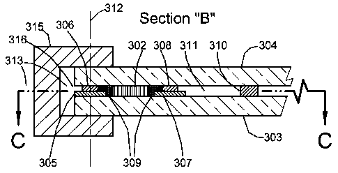
barrier 309 that will become partially interposed between strip spacers 307
and 308 will not
exceed the pressure of viscous material 302. By limiting the pressure of the
thin film of
viscous barrier 309 between strip spacers 307 and 308 to that of viscous
material 302 any
tendency to "pump" viscous barrier 309 between spacers 307 and 308 and into
vacuum space
311 is mitigated. The rough surface 317 increases the frictional forces on the
thin film of
viscous barrier 309 between spacers 307 and 308 and thereby increases the
resistance of
viscous barrier 309 to creep between spacers 307 and 308 and into evacuated
space 311.
[0070] Ongoing rheological tests at three times atmospheric pressure have yet
to reveal
any sign of creep of a preferred material for viscous barrier 309 through a
gap larger than that
created by the rough surface of 317.
16
CA 02793476 2012-09-17
WO 2011/126670
PCT/US2011/028264
100711 FIG. 5 is the same cross sectional view as FIG. 3 but under the
condition that
the ambient air temperature on one side of the unit is lower than on the other
as would occur
if the unit was in service and it was colder outdoors. When glass sheets 303
and 304 move
laterally relative to one another 320 as a result of thermal strain or for any
other service
related reason, viscous material 302 undergoes viscous shear through a shear
angle 319 with
very little shear stress while maintaining adhesion to glass sheets 303 and
304 under thc no-
slip condition for viscous fluids. In this manner viscous material 302 cannot
fail as a seal
because of tensile rupture, adhesive failure, cold brittle fracture, material
breakdown, strain
hardening, dclamination, fatigue, bond failure, shear rupture, puncture, or by
inducing failure
stresses in glass sheets 303 and 304. The low shear stress assures that glass
sheets 303 and
304 will not bulge. Because the shear is viscous shear, where shear stress is
a function of
shear rate, once relative motion between glass sheets 303 and 304 stops there
is no shear
stress and of course no shear stress induced compressive or tensile stresses
in glass sheets 303
and 304. This is not the case for elastic materials where stress persists
after motion stops
whether or not the strains are in the elastic or inelastic range. Therefore,
given a viscous edge
seal as disclosed by this embodiment, stresses in glass sheets 303 and 304 are
not a function
of static relative lateral displacement 320 between glass sheets 303 and 304.
Therefore the
size of a VIG unit with a viscous edge seal may be limited only by the
practical size of
producing glass sheets 303 and 304. This is not the case for the metal edge
seals disclosed by
Pub. Nos. US 2008/01665570 Al, US 2009/0155499 Al, US 2010/0178439 Al, and US
2010/0034996 Al, where the edge seals are subject to elastic and inelastic
stress and strain
and limited by strain at ultimate strength. An edge seal design that does not
limit the size of a
VIG unit is significant. Larger VIG units are more energy efficient because
per square foot of
window there can be less lineal footage of heat conducting edge seal.
[0072] Referring to FIG. 5, when lateral relative movement 320 occurs between
glass
sheets 303 and 304 as a result of thermal strain the space bounded by glass
sheets 303 and
304 and spacers 305, 306, 307, and 308 does not change significantly and by
geometric proof
the volumes occupied by viscous barrier 309 do not significantly change.
Therefore, given
this type of relative movement, viscous barrier 309 redistributes to new
shapes within the
same volumes.
[0073] Changing indoor and outdoor temperatures will cause the components of a
VIG
unit to expand and contract differentially, including viscous material 302 and
viscous barrier
309. As a result, the dimensions of the spaces that contain viscous material
302 and viscous
barrier 309 will change. To accommodate this, viscous material 302 has a free
surface 321
across the top of the unit as depicted in FIG. 6 that rises and falls as does
the free surface of
any fluid whose container changes dimensions. Also shown in FIG. 6 is a break
324 in strip
spacer 305 to allow pressure equalization.
17
CA 02793476 2012-09-17
WO 2011/126670
PCT/US2011/028264
[0074] By way of illustration only, in some embodiments, the viscous material
used in
the edge seal will have a gas permeability of no greater than about 1,000,000
(centimeter' =
millimeter/meter2= day bar) for oxygen gas at 20 C, as measured by ASTM D
3985. This
includes embodiments in which the viscous material has a gas permeability of
no greater than
about 100,000 (centimeter3 = mm/m2 = d = bar) for oxygen gas at 20 C, as
measured by ASTM
D 3985, and further includes embodiments in which the viscous material has a
gas
permeability of no greater than about 10,000 (centimeter3 = mm/m2 = d = bar)
for oxygen gas at
20 C, as measured by ASTM D 3985, and further includes embodiments in which
the
viscous material has a gas permeability of no greater than about 1,000
(centimeter3 = mm/m2 =
d = bar) for oxygen gas at 20 C, as measured by ASTM D 3985.
[0075] The desirable viscosity of the low permeability viscous material may
vary over a
wide range depending upon a variety of factors, including the method used to
apply or
dispose the viscous material in the edge seal. By way of illustration only, in
some
embodiments, the low permeability viscous material will have a viscosity of no
greater than
about 90,000,000 (mPa = s) at 20 C. This includes embodiments in which the
low
permeability viscous material has a viscosity of no greater than about
1,000,000 (mPa = s) at
20 C, further includes embodiments in which the low permeability viscous
material has a
viscosity of no greater than about 10,000 (mPa = s) at 20 C, still further
includes
embodiments in which the low permeability viscous material has a viscosity of
no greater
than about 1,000 (mPa = s) at 20 C, still further includes embodiments in
which the low
permeability viscous material has a viscosity of no greater than about 100
(mPa = s) at 20 C
and still further includes embodiments in which the low permeability viscous
material has a
viscosity of no greater than about 1 (mPa = s) at 20 C.
[0076] A viscous material with low gas permeability suitable for material 302
would be
a cold flowing Newtonian fluid such as a low to medium molecular weight
polyisobutene or
PIB. The gas permeability of polyisobutene is one of the lowest for polymers
and against
which the permeability of other polymers is compared. In the form of elastic
butyl rubber it
lines all tires to prevent permeation of air out of the tires. P1B is inert,
nontoxic, and stable
indefinitely. Specifically, PIB manufactured by the chemical company BASF
under the trade
name Oppanol B10 has suitable viscosity. Other molecular weight grades of PIB
may be
suitable for this invention. For example, BASF makes a family of low molecular
weight PIB's
under the trade name Glissopal. Under some embodiments of this invention
Glissopal or some
formulation combining Glissopal and an Oppanol B may be an optimal choice for
the viscous
material 302 with low gas permeability. The choice may depend on the
particular barrier or
barriers used to segregate the PIB from the evacuated space 311 and or on the
particular
method used to place the PIB into assembly. Oppanol B10 has atmospheric gas
permeability
on the order of 10-1 cm3=mm/(cm2-sec=torr). This compares favorably with the
gas
18
CA 02793476 2012-09-17
WO 2011/126670
PCT/US2011/028264
permeability of metals 10 10 cm3.mm/(cm2.see=torr), and of glasses 10 12 to 10
13
CM3'mml(cm2. sec torr).
[0077] Given the metal and solder glass edge seal thicknesses disclosed by the
prior art,
a two inch wide strip of viscous material 302 consisting of PIB would have a
reduced rate of
permeation compared to the metal seals and an increased rate of permeation
relative to the
solder glass seals of only a factor of ten. Given that the edge seal accounts
for only 1/1000 to
1/5000 of the permeable surface of a vacuum insulating glass unit, any loss of
service life of a
VIG unit with a viscous PIB edge seal, compared to a unit with a solder glass
edge seal,
would be negligible. If a VIG unit has a permanently attached or temporarily
attachable pump
out port to which a vacuum pump can be attached in order to pump down the
vacuum every
couple of decades then the difference between the permeation rates of a solder
glass edge seal
and a two inch wide viscous edge seal composed of PIB is inconsequential.
[0078] Oppanol B10 is a Newtonian fluid. A Newtonian fluid is one where shear
stress
is proportional to shear rate. The constant of proportionality is defined as
the material's
viscosity. If Oppanol BIO were used for the embodiment shown in FIG. 3 with a
gap of 0.02
inches between glass sheets 303 and 304, shear stresses caused by changing
temperature
differentials between inside and outside while the unit is in service would
result in tensile and
compressive forces in glass sheets 303 and 304 on the order of fractions of a
pound force per
lineal inch of glass edge.
[0079] Oppanol B10 exhibits cold flow. Unless confined, any force exerted on
it will
cause it to flow and keep flowing. For example, if a container of Oppanol B10
is tipped over
without a lid its contents will slowly spill out. Like water it seeks its own
level and exerts
hydrostatic pressure. If an object with greater specific gravity is placed on
the surface of
Oppanol B10 it will slowly sink to the bottom. If the object's specific
gravity is less than
Oppanol B10 it will float on the surface.
[0080] The term "viscous barrier" is used to refer to a viscous material that
may be used
in an edge seal along with the low permeability viscous materials described
above. This term
is used for clarity to distinguish the two materials in those embodiments in
which they are
used together in an edge seal. By way of illustration only, in some
embodiments, the viscous
material of the viscous barrier will have a vapor pressure of no greater than
about 10-s torr.
This includes embodiments in which the viscous material of the viscous barrier
has a vapor
pressure of no greater than about 10 6 torr, and further includes embodiments
in which the
viscous material of the viscous barrier has a vapor pressure of no greater
than about 10 torr.
A suitable material for viscous barrier 309 is the high temperature vacuum
grease
manufactured by M & I Materials Ltd under the trade name Apiezon H. Apiezon H
is
relatively stiff grease with a vapor pressure at 20 degrees Celsius of 1.7 X
10-9 torr. Apiezon
H is inert and stable indefinitely. It will not melt and gets stiffer as its
temperature increases.
19
CA 02793476 2012-09-17
WO 2011/126670
PCT/US2011/028264
This particular characteristic is important because it will not soften if, for
example, during
VIG unit fabrication polyisobutene at an elevated temperature and lowered
viscosity is
pumped between glass sheets 303 and 304. Also of importance is the fact that
the specific
gravity of Apiezon H is virtually identical to that of polyisobutene.
[0081] Vacuum greases such as Apiezon H are primarily employed in vacuum
sealing
applications involving fixed o-ring or gasket seals or in rotary motion seals
and where the
vacuum space is under continual or short term intermittent pumping to maintain
the vacuum
at the desired level. They are also used in sealing ground glass stop cocks
used in chemistry
glassware. But here again the vacuums arc maintained for short periods or arc
under
continuous or short term intermittent pumping to maintain the vacuum. The
importance of
such greases has to do with their low vapor pressure and lubricating
properties and with their
ability to at least reduce gas leaking through the surface imperfections of o-
rings and gaskets.
Greases are generally not Newtonian fluids and under shear their shear stress
is not
proportional to the rate of shear but instead the relationship between shear
stress and shear
rate for greases takes more complicated nonlinear forms.
[0082] Use of vacuum greases in vacuum sealing applications does not suggest
their use
as a viscous material for edge sealing VIG units. To the contrary, the types
of vacuum sealing
applications where vacuum grease is employed suggest that it is not a viscous
material
suitable for restricting the permeation of gas through a VIG edge seal.
[0083] FIG. 7 is the same cross section as in FIG. 3 but with modification to
more fully
delineate the scope of the invention. The modification is that the strip
spacers 305 and 307 are
joined by a strip of the same material to become one strip spacer 322 and
strip spacers 306
and 308 are similarly joined to become one strip spacer 323. Viscous low gas
permeability
material 302 is then no longer in contact with glass sheets 303 and 304.
Unitizing strip
spacers 305 and 307 and strip spacers 306 and 308 may speed VIG unit assembly
times and
reduce the area presented by viscous low gas permeability material 302 for gas
to permeate
through.
[0084] FIG. 8 is a cross sectional view (as referenced by FIG. 1) of the edge
region of
a VIG unit according to a second embodiment of this invention showing an edge
seal that
comprises viscous material 802 with low gas permeability and barriers to
constrain viscous
material 802 that include: glass sheets 803 and 804; strip spacers 805, 806,
807, and 808;
lubricating low vapor pressure viscous barrier 809; and end cap 815. FIG. 8
shows the edge
region under the condition that the ambient air temperatures on either side of
the unit are the
same, as would occur if the unit was in service in a building and the indoor
and outdoor
temperatures were the same. Viscous material 802 with low gas permeability and
viscous
barrier 809 may continue unbroken around the edge regions of glass sheets 803
and 804. Strip
spacers 805, 806, 807, 808, and end cap 815 may continue unbrokcn around the
edge rcgions
CA 02793476 2012-09-17
WO 2011/126670
PCT/US2011/028264
of glass sheets 803 and 804. End cap 815 may place a clamping or compressive
force against
glass sheets 803 and 804. Glass sheets 803 and 804 are separated by an array
of spacers 810
and by strip spacers 813 and 814. Strip spacers 813 and 814 may continue
unbroken around
the edge regions of glass sheets 803 and 804. The space 811 between glass
sheets 803 and
804 is a vacuum at a pressure less than atmospheric, preferably less than 104
torr. The low
pressure vacuum space 811 greatly reduces convective and conductive heat
transfer between
glass sheets 803 and 804. Strip spacers 805 and 807 may be cemented to glass
sheet 803 and
strip spacers 806 and 808 may be cemented to glass sheet 804. End cap 815 is
free to move
relative to spacers 805, 806, 807, and 708. When there is relative lateral
movement between
glass sheets 803 and 804 some portion of viscous material 802 will undergo
viscous shear.
[0085] FIG. 9 is a cross sectional view (as referenced by FIG. 1) of the edge
region of
a V1G unit according to a third embodiment of this invention showing an edge
seal that
comprises viscous material 902 with low gas permeability and barriers to
constrain viscous
material 902 that include: glass sheets 903 and 904, elastic membrane 905, and
end cap 906.
Elastic membrane 905 is cemented or otherwise affixed to glass sheets 903 and
904. Elastic
membrane 905 need not have low gas permeability so it can be made of a
material and with a
thickness that stretches easily and with very little force. FIG. 9 shows the
edge region under
the condition that the ambient air temperatures on either side of the unit are
the same as would
occur if the unit was in service in a building and the indoor and outdoor
temperatures were the
same. Glass sheets 903 and 904 are separated by an array of spacers 907 and by
strip spacer
908. Viscous material 902, elastic membrane 905, end cap 906 and strip spacer
908 may
continue unbroken around the edge regions of glass sheets 903 and 904. The
space 911
between glass sheets 903 and 904 is a vacuum at a pressure less than
atmospheric, preferably
less than 104 torr. The low pressure vacuum space 911 greatly reduces
convective and
conductive heat transfer between glass sheets 903 and 904. End cap 906 may
place a
clamping or compressive force against glass sheets 903 and 904. End cap 906 is
not affixed to
glass sheets 903 and 904 and is free to move relative to glass sheets 903 and
904. When there
is relative lateral movement between glass sheets 903 and 904 some portion of
viscous
material 902 will undergo viscous shear.
[0086] FIG. 10 is a cross sectional view (as referenced by FIG. 1) of the edge
region of
a VIG unit according to a fourth embodiment of this invention showing an edge
seal that
comprises viscous material 1002 with low gas permeability and barriers to
constrain viscous
material 1002 that include: glass sheets 1003, 1004, and end cap 1005. Viscous
material with
low gas permeability 1002 and end cap 1005 may continue unbroken around the
edge regions
of glass sheets 1003 and 1004. The space 1006 between glass sheets 1003 and
1004 is a
vacuum at a pressure less than atmospheric pressure, preferably less than 104
torr. The low
pressure vacuum space 1006 greatly reduces convective and conductive hcat
transfer between
21
CA 02793476 2012-09-17
WO 2011/126670
PCT/US2011/028264
glass sheets 1003 and 1004. Maintaining separation between glass sheets 1003
and 1004 are
micro sized spacers 1007 that may be made of, for example, nanoparticles or
nanotubes.
Viscous material 1002 is prevented from creeping into space 1006 by surface
tension at the
leading edge of material 1002 that is bounded by vacuum space 1006. This is
made possible
by the extremely close spacing of glass sheets 1003 and 1004. When there is
relative lateral
movement between glass sheets 1003 and 1004 some portion of viscous material
1002 will
undergo viscous shear.
[0087] FIG. 11 shows a schematic plan view of a VIG unit with a vacuum 1101
and an
array of spacers 1102 between glass sheets 1103 and 1104 as depicted in FIG.
12, which is a
sectional view of FIG. 11. Glass sheets 1103 and 1104 are rigidly joined to
one another at
1105. Edge seal 1107 may be any of the first through fourth embodiments
disclosed herein.
Glass sheets 1103 and 1104 are free to expand and contract independently of
one another yet
remain fixed at point 1105. The rigid contact point 1105 prevents glass sheets
1103 and 1104
from "walking" their way out of registration with one another as a result of
repeated cycles of
expansion and contraction of glass sheets 1103 and 1104. The embodiment of a
VIG unit as
disclosed by FIG. 11 underscores that the viscous edge seals as disclosed
herein need not be
continuous and without break.
100881 FIG. 13 is a schematic plan view of a VIG unit that diagrams a process
suitable
for the first embodiment, herein depicted in FIG. 3 through FIG. 6, for
placing a viscous low
gas permeability material 1306 into assembly between glass sheets 1301 and
1302. FIG. 14 is
a section of FIG. 13. Glass sheets 1301 and 1302 have a vacuum 1303 in between
them and
are separated by an array of spacers 1304. The assembly process is as follows:
first, glass
sheets 1301 and 1302 arc placed together so as to sandwich all of the spacers
between thcm;
second, edge caps, 315 in FIG. 3, are pressed onto the edges; third, viscous
low gas
permeability material 1306 is pumped through holes 1307 in glass sheet 1302
while
maintaining lower pressures at holes 1308; fourth, viscous material 1306 flows
1309 toward
holes 1308; fifth, after the viscous material has been placed, holes 1307 and
1308 are sealed
with caps.
[0089] Any method to seal a VIG unit that comprises two glass sheets with a
vacuum
space in between must include one or more low gas permeability materials that
bridge or span
the gaps between the glass sheets so as to seal off and maintain the vacuum.
The most
advantageous places to bridge those gaps are in the edge regions of the glass
sheets. Examples
in the art show that combinations of different materials may be used to bridge
the gaps. Those
materials may be configured in literally an infinite number of ways. As
examples, the
materials may be entirely between the glass sheets, or entirely outside the
space between the
glass sheets, or they may be partially between the glass sheets.
22
CA 02793476 2012-09-17
WO 2011/126670 PCT/U
S2011/028264
100901 The commonality among the infinite number of possible embodiments for
this
invention is that a viscous material bridges or spans some portion of the gap
between the glass
sheets of a VIG unit and that relative lateral movement between the glass
sheets is
accommodated by the viscous material undergoing viscous shear. It is
contemplated that the
scope of this invention encompasses all of the infinite number of ways that a
viscous material
might bc configured and constrained so as to function in the above described
manner.
REFERENCES CITED: OTHER PUBLICATIONS
Jousten K, editor. Handbook of Vacuum Technology. Wcinheim, Germany: Wiley-
VCH;
2008. 1002 p.
Le Bourhis E. 2008. Glass, Mechanics and Technology. Weinheim, Germany: Wiley-
VCH. 366p.
Macosko C. W. 1994. Rheology, Principles, Measurements, and Applications. New
York:
Wiley-VCH. 550 p.
Morrison F. A. 2001. Understanding Rheology. New York: Oxford University
Press. 545
p.
Nippon Sheet Glass. 2003. Precaution For Use and Maintainance [sic]. 1 screen.
Available from: http://www.nsg-spacia.co.jp/techiwarranty.html
O'Hanlon J. F. 2003. A User's Guide to Vacuum Technology, 3rd Ed. Hoboken, NJ:
John
Wiley & Sons. 516 p.
Roth A. 1994. Vacuum Sealing Techniques. Woodbury, NY: American Institute of
Physics. 845 p.
23