Note: Descriptions are shown in the official language in which they were submitted.
CA 02793648 2015-10-30
WO 2011/116221 PCT/US2011/028863
1
System for Purifying Certain Cell Populations in Blood or Bone marrow by
Depleting
Others
RELATED APPLICATIONS
[0001] This application claims priority from the United States provisional
application
having Serial Number 61/315,109, filed March 18, 2010, and from United States
provisional
application having Serial Number 61/436,964, filed January 27, 2011.
BACKGROUND
Field of the Invention
[0002] The present invention relates to a cell separation system, and in
particular to a
system for depleting certain blood components from normal blood,
placental/umbilical cord
blood, bone marrow, or stromal vascular fraction (SVF) cells once separated
from adipose
tissue.
Background of the Invention
[0003] Normal human blood generally comprises platelets ("PLTs"), plasma,
red blood
cells ("RBCs"), white blood cells (-WBCs"), and, in very small quantities,
stem and
progenitor cells (SPCs). On average (known to vary among individuals and, over
time,
within the same individual) RBCs make up approximately 99.9% of the number of
an
individual's total blood cells and account for approximately 45% of an
individual's total
blood volume. RBCs serve a vital function as the principal means of delivering
oxygen to
the body tissues. Nearly all of the remainder of an individual's blood volume
is made up of
plasma, a non-cell liquid component of blood accounting for approximately 55%
of the total
blood volume and in which all blood cells are suspended.
[0004] Thus, over 99% by volume of nounal blood is made up of plasma and
RBCs. The
remaining approximately <0.6% by volume of normal blood consists of all other
blood cell
types and PLTs. PLTs are small, irregularly shaped anuclear cells that
outnumber the WBCs
by a factor of ¨10. PLTs play a fundamental role in wound care by stopping
bleeding and
releasing a multitude of growth factors that repair and regenerate damaged
tissue.
[0005] The next most prevalent blood cells are WBCs, making up by number
only about
one tenth of one percent of the total cells in a typical blood sample.
However, WBCs are
critical to the body's immune system and defend the body against both
infectious disease and
foreign materials. The WBCs may be further divided into smaller subgroups. The
largest
CA 02793648 2012-09-18
WO 2011/116221 PCT/US2011/028863
2
such subgroup is granulocytes (GRNs), making up approximately 60% of all WBCs,
and the
other approximately 40% being mononuclear cells (MNCs). Throughout this
application, the
use of the term WBC may indicate a reference to exclusively GRNs, exclusively
MNCs, or
some combination of both.
[0006] MNCs can further be broken down into lymphocytes and monocytes, but
may
collectively be referred to as MNCs due to the presence in each cell of a
single round nucleus.
MNCs are critical elements of the immune system, comprising T cells, B cells
and NK cells
that migrate to sites of infection in body tissue and then divide and
differentiate into
macrophages and dendritic cells to elicit an immune response. Finally, the
MNCs
themselves can be further divided into even smaller subclasses - - including
extremely small
quantities of multipotent hematopoietic (blood forming) stem and progenitor
cells and
mesenchymal (bone, fat, cartilage, muscle and skin forming) stem and
progenitor cells, both
critical to human health. Another source of MNCs are the stromal vascular
fraction cells
(SVFCs) that have been separated from adipocytes removed from individuals
during
liposuction.
[0007] Samples of normal blood, placental/umbilical cord blood or bone
marrow are
drawn in excess of 25 million times per year in the industrial world. Because
the samples are
generally taken either as a part of research into treatment of disease or for
direct clinical
treatment, the blood cells most often isolated are WBCs, followed by MNCs.
MNCs include
all the stem and progenitor cells, and approximately 40% of the critically
important immune
cells. Thus the cells most often in demand represent only a very small
fraction of the cells
drawn for a typical sample.
[0008] Thus if a relatively purified population of cells containing
essentially all the stem
and progenitor cells (SPCs) and depleted of substantially all the RBCs is
desired, there is a
need to separate the components of blood or bone marrow described above so as
to isolate
the WBCs or, if more purity is desired, the MNCs. This need for consistent,
effective
processes to separate these cell populations and harvest the target cells is
especially pressing
due to the increasing demand for SPCs for research, clinical trials, and point
of care medical
practices.
[0009] The interest in and research conducted on SPCs is staggering. As of
November
2010 over 100,800 stem cell research articles have been published worldwide.
There are
currently at least 7,000 principle researchers focused on SPCs worldwide. In
the United
States alone there are some 300 stem cell research centers and approximately
10,000
individual labs. As a result of this extensive research has 199 clinical
trials with cord blood
CA 02793648 2012-09-18
WO 2011/116221 PCT/US2011/028863
3
stem cells, 34 clinical trials using adipose tissue, and 1,405 clinical trials
using bone marrow
stem cells are now underway according to clinicaltrials.gov, the NIH website.
Description of Related Art
[0010] Conventional methods of isolating and harvesting certain cell types
from a whole
blood or bone marrow aspirate sample generally involve centrifugation of the
sample. During
centrifugation, populations of cells tend to migrate to a relative position
along the axis of
lesser to greater acceleration according to their density, and concentrate in
layers, displacing
other higher and lower density cell types and plasma during the process.
[0011] Fig. 1 shows the density and average diameter of various cell types
found in
human blood. The physical differences between different cell types are
important when the
blood is centrifuged. When the blood is centrifuged the cells begin to move to
new locations
at velocities that are in accordance with many fluid dynamic factors,
including Stokes Law.
The fact that all cells retain a slight negative charge militates against
direct cell-membrane-
to-cell-membrane contact. In an environment comprising mainly plasma, with
relatively few
cells, the larger the cell, the more rapidly it travels. However as the
concentration of cells
rises, the effect of cell charge begins to substantially determine cell
velocity.
[0012] However, in all cases, the denser the cell, the lower in the
container (that is,
further from the axis of centrifuge rotation) it will ultimately migrate to
and settle. Thus, as
shown in Fig. 2, the densest cells, RBCs (having a density between 1.08 and
1.12), will
migrate to the bottom of the container being centrifuged. Within the RBC layer
the nucleated
red blood cells (which exist in both cord blood and bone marrow but not in
normal blood)
will be at the top of the red cell fraction. On top of the RBCs will be the
GRNs (density
1.07-1.11), then, in order moving closer to the axis of rotation in the
container, the
lymphocytes (density 1.05-1.09), monocytes (density 1.045-1.0750) and the PLTs
(1.03-
1.065). It is known that the SPCs have a density closest to monocytes and
lymphocytes and
thus can be captured if those more numerous cells are captured. By taking
advantage of the
known strata that form under certain conditions, harvesting of one type of
cell can be
facilitated through the harvesting of only its strata. Fig. 2 also shows the
relative frequency
of the blood cell types in typical samples of normal blood, cord blood and
bone marrow, and
finally shows that there is some overlap in cell populations organized by
density, as will be
discussed below.
[0013] While creating the stratified cell layers generally requires nothing
more than the
application of high G forces over a set amount of time, precisely removing a
specific layer of
cells is problematic. To illustrate the rarity and small volume of certain
cell populations in a
given sample, Figs. 3, 4, and 5 detail the respective average volumes of each
cell population
CA 02793648 2012-09-18
WO 2011/116221 PCT/US2011/028863
4
in normal blood (NB), cord blood (CB) and bone marrow (BM) after
centrifugation and
stratification.
[0014] Figs. 3 and 4 illustrate that the vast majority of cells are RBCs,
while Fig. 5
shows clearly that the volumes of non-RBC cellular blood components are so
small that even
with a 200 ml sample of cord blood the total volume of all GRNs (top line),
MNCs (middle
line) and PLTs (lower line) is about 1 mL. In cord blood fewer than 1 out of
every 1,000
blood cells (approximately 0.08% of total cells) is an MNC. In a cord blood
sample
including 10,000 RBCs, one would expect to find 40-200 PLTs, 3-6 MNCs, and 5-
10
granulocytes.
[0015] As explained, the vast majority of blood by both number of cells and
by volume is
made up of cells other than WBCs. Because of the scarcity of these WBCs and
their
residence within liquid solutions populated by enormous numbers of RBCs,
current methods
to isolate WBCs are (A) labor and time intensive, requiring excellent
laboratory technique,
(B) typically cannot be accomplished in a sterile environment, (C) typically
have only
between a 50-75% efficiency rate in capturing WBCs (a loss of 25% to 50% of
the WBCs),
and (D) involve processes that may adversely affect cell function. Given the
typically small
size of blood samples and the fact that SPCs are exceedingly rare in normal
blood, there may
be no SPCs at all in a typical harvest of the WBCs from normal blood and,
although SPCs
are more numerous in cord blood than in normal blood, they are still rare in
cord blood.
[0016] To further illustrate how difficult it is to obtain WBCs from normal
blood, a
diagrammatic 50 ml test tube normally used in conventional manual blood
component
separation methods is shown in Fig. 6. These tubes are typically 28 mm in
width. After
centrifugation the separated blood components are the plasma (top) and the
RBCs (bottom)
and a nearly invisible thin layer called a "buffy coat" disposed in between
(exaggerated in
size in Fig. 6 for purposes of illustration). This "buffy coat" contains
nearly all the WBCs,
SPCs and PLTs.
[0017] Although several semi-automated systems for harvesting WBCs from
whole
blood are currently being marketed, their advantage in cell recovery
efficiency relative to
manual methods is not significant, and their market penetration is small. The
prevalent
current methods for isolating and capturing WBCs within a blood or bone marrow
sample
employ two manual processing technologies (A) the density gradient granules
method and
(B) the density gradient disk method. For diagnostic or research purposes, it
is estimated that
ninety-nine times out of a hundred when WBCs are isolated from blood or bone
marrow they
are isolated using these technologies. Both typically utilize cylindrical
tubes for the process,
and both rely on the carful manipulation of densities. For example, if the
goal is to isolate
CA 02793648 2012-09-18
WO 2011/116221 PCT/US2011/028863
MNCs, many thousands of tiny granules or a disk (of slightly smaller diameter
than the tube
inner diameter) with a density of approximately 1.08 are placed in the tube.
This specific
density value is chosen as it is equidistant between the median densities of
GRNs and
lymphocytes (see Fig.2). In order to function correctly, both these
technologies require that
the blood sample first be diluted with an amount of buffer equal to 2 to 4
times the blood
volume.
[0018] Referring first to the granule method, after the buffered blood
sample is mixed
with the granules in the test tube, centrifugation is initiated. During
centrifugation, the
density of the granules causes them to coalesce such that they divide the
RBCs/GRNs from
the MNCs/PLTs. Fig. 7 illustrates this process with Ficoll density gradient
granules dividing
the MNCs from the RBCs/GRNs.
[0019] The method of using density gradient disks is very similar and is
illustrated in
Fig. 8. Here, the disks of density 1.08 migrate under centrifugation to the
interface between
lymphocytes and GRN. However, most density gradient disks contain one feature
not found
in the granules above: they comprise a cavity between the upper and lower
disks where it is
expected the MNCs will settle, thus somewhat simplifying the step of
harvesting of MNCs
via a flexible tube that travels between the cavity and the top of the tube.
[0020] These manual methods for isolating and capturing MNCs from a blood
sample
require patience and excellent manual dexterity. These methods typically
require 11/2 to 2
hours to perform, and even with best practices, recovery of MNCs is often less
than 60%.
Thus the manual methods commonly employed for isolating and capturing MNCs
within a
blood sample are less than optimal in terms of precision and speed because of
numerous
limitations in this technology.
[0021] First, density gradient solutions achieve isolation of a population
of WBCs from
blood or bone marrow by relying on only one physical factor --density. Once
the
centrifugation begins, the density gradient medium moves to a position where
it is buoyant in
the cell solution and stops. Typically, this migration of the cell populations
to their final
positions occurs during an acceleration and duration that are both fixed, and
thus rarely
optimal for an individual blood sample.
[0022] Essentially the WBC or MNC harvesting efficiency of both density
gradient
technologies is limited by the need to aim at the center of the gap between
the median density
bell curves of the granulocytes and the lymphocytes (i.e., 1.08), as mentioned
above with
regard to Fig. 2. As Fig. 2 makes clear, this fixed density clearly does not
exclude all the
granulocytes or even all RBCs and does, in fact, discard some of the desired
lymphocytes.
CA 02793648 2012-09-18
WO 2011/116221 PCT/US2011/028863
6
[0023] This simplistic approach also does not accommodate the fact that
even in
normally healthy people, there exists significant variation in the number and
density of cells
of each type and the sedimentation rates among samples may differ by as much
as an order of
magnitude. Further, if the patient has certain diseases the variation in the
relative cell
populations and the sedimentation rates of the cells can be much greater¨up to
two orders of
magnitude. Consequently, these primitive WBC or MNC isolation technologies are
rarely
optimal for any specific sample of blood.
[0024] The best way to conceive of the severity of this limitation is to
understand that the
cells in a sample of blood, evenly distributed throughout the volume prior to
centrifugation,
begin a race to a new location when centrifugation begins. The efficiency of
the WBC or
MNC isolation technology depends upon how precisely all the WBCs wind up at
the same
strata at the end of the race---and how well the technician can extract the
WBCs from this
location with a pipette at normal 1G conditions where the cells will begin to
remix with only
the slightest motion of the container, or the slightest motion of the pipette
tip.
[0025] Scientists have long studied the rate at which RBCs from normal
blood migrate
down a container under 1G conditions. This measurement is called the
erythrocyte
sedimentation rate, or ESR. Although the centrifugal acceleration used in
conventional MNC
isolation processes accelerate this rate of sedimentation, they do not change
the percentage
variation of the sedimentation rates of the different cell types. Further, as
RBCs are more
than 1000 times as numerous as WBCs and 2000 times as numerous as MNCs, and
all the
cells maintain a slight negative charge, it is the RBC migration that most
effects isolating the
WBC populations.
[0026] The ESR (measured in millimeters per hour---mm/hour) in adults of
various age
are shown in Fig. 9. In children, normal values of ESR have been found to be 1
to 2 mm/hour
at birth, rising to 4 mm/hour 8 days after delivery, and then to 17 mm/hour by
day 14 (a
change of more than an order of magnitude in less than two weeks). The ESR is
so variable
that it is used to diagnose malignant diseases, such as multiple-myeloma,
various auto-
immune diseases such as rheumatoid arthritis, and chronic kidney diseases
wherein the ESR
may exceed 100 mm/hour, five times that of a normal adult.
[0027] Further, it is noted that WBCs at the bottom of a container can only
move upward
to join those descending from the top of the container as a result of being
buoyed up on the
ascending plasma displaced by the descending RBCs. Note that the very small
number of
WBCs in a solution must negotiate their path upwards against the flow of RBCs,
a thousand
times more numerous, moving in the opposite direction through the same
vertical channel.
Further, as the acceleration and duration of the centrifuge is programmed at
the start of the
CA 02793648 2012-09-18
WO 2011/116221 PCT/US2011/028863
7
run, a duration that is satisfactory to relocate all the cells within a
specific sample may be
insufficient for many other blood samples in that most of the RBCs may not
have arrived at
the bottom of the tube and thus many of the target WBCs may not have been
buoyed up to
the "buffy-coat" strata by the ascending plasma. As this process takes place
in a closed
centrifuge within a rapidly spinning rotor, the operator is unable to observe
the actual motion
of the cells.
[0028] There is thus a need for a system, which optically tracks, in real
time, the
migration of cell populations within each individual blood sample during
centrifugation.
Such a system would allow each individual blood sample to be custom processed
according
to the specific size and density of that blood sample's constituent cell
populations. This
improved solution should also greatly increase the harvesting efficiency of
target WBC or
MNC cell populations.
[0029] A further drawback to density gradient mediums is that they require
buffers,
which occupy most of the volume of a given harvest tube, minimizing the volume
of blood
from which WBCs are to be harvested. A buffer often occupies 70% to 90% of the
50 ml
volume of a typical harvest tube, leaving space for only 5 to 15 ml of blood.
Consequently, a
technician who needs to harvest WBCs from 100 ml of blood must employ 7 to 20
test tubes-
--further increasing the labor required to accomplish the goal. Additionally,
in order to
achieve adequate purity from contaminants in the final WBC population, the
granular density
gradient mediums and the buffers will need to be washed out, inevitably
causing a further
loss of target cells.
[0030] There is thus a need for a means for depleting undesired cells from
a blood or
bone marrow sample, which does not require voluminous density gradient mediums
or
buffers. The means may optionally allow the harvest of WBCs from larger volume
samples,
further increasing the number of constituent cells that may be recovered for
diagnostic or
clinical use.
[0031] A third drawback to the density gradient based blood separation
methods
described above is that the parallel vertical walls of a density gradient
harvest tube do not
assist the WBCs rising during centrifugation to lie atop the RBCs. The density
gradient
harvest test tubes in conventional systems have vertical parallel walls
meaning that during
centrifugation all the cells either fall or rise vertically along the axis of
the tube. As
described above, each ascending WBC must negotiate thousands of RBCs moving in
the
opposite direction. The harvest test tube's parallel vertical walls provide no
lateral motion to
descending RBCs and ascending WBCs that could assist the rise of the WBCs
during
centrifugation. As a result a significant portion of the WBCs that began the
spin cycle in the
CA 02793648 2012-09-18
WO 2011/116221 PCT/US2011/028863
8
bottom of the tube may not rise to the harvest "buffy coat" layer during the
chosen
centrifugation regimen.
[0032] There is thus a need to overcome the entrapment of WBCs at the
bottom of the
test tube through utilization of a funnel-shaped harvest chamber that
radically narrows at the
bottom, such that most of the descending RBCs are forced to the center,
enhancing eddy
currents led by the lightest of the RBCs ascending to the top of the RBC
volume. In turn
these eddy currents assist the ascension of the much less numerous but more
buoyant WBCs.
[0033] A fourth drawback to the density gradient based separation methods
is the
constant large cross sectional area of the density gradient harvest test tube
at the location
where the MNCs are harvested manually at 1 G.
[0034] Because the walls of a standard 50 ml density gradient harvest tube
are a fixed
¨28 mm apart, the very small volume of MNCs from a 10 ml peripheral blood
sample
(-0.028 ml) are spread across the entire cross sectional area of the tube (-
615 mm2) in a thin
layer (-0.023 mm) which is nearly invisible. Because of this broad cross
sectional area and
the resulting thin layer of MNCs, the stratifying effects of the density
differences between
cell populations are miniscule. Consequently, harvesting the MNCs at 1 G
requires a highly
trained technician to slowly and carefully insert a pipette tip into this very
thin layer of cells
that floats between the density gradient (below) and plasma (above) and then
gently apply a
suction to draw the MNCs up into the pipette. However, the very small density
variations
between cell populations, when not magnified by substantial centrifugal
forces, and the large
cross sectional area of the tube conspire to keep the MNCs/PLTs essentially
all in the same
thin vertical layer. Consequently, no amount of care during this manual
suction process
prevents the roiling of the MNC/PLT layer and the density gradient media so a
loss of MNCs
and substantial contamination of the cells by the density gradient granules
ensues. It is thus
not uncommon to lose ¨25-40% of the MNCs during this procedure.
[0035] There is thus a need to avoid losses during the harvest of MNCs by
depleting
RBCs and most of the GRNs through the narrow cross sectional area of a funnel
exit while
substantial centrifugation maintains the integrity and purity of the cell
strata and elongates
them vertically as they descend down the tapered funnel.
[0036] A fifth drawback to conventional density gradient granule based
systems is due to
the direct contact between the density gradient granules and the cells. The
extensive direct
contact between these granules and the cells to be harvested has been reported
to damage the
cell function due to a form of toxicity. For example, Yuhan Chang, et al
recently reported in
"The Efficiency of Percoll and Ficoll Density Gradient Media in the Isolation
of Marrow
Derived Human Mesenchymal Stem Cells with Osteogenic Potential" (Chang Gung
Med J
CA 02793648 2012-09-18
WO 2011/116221 PCT/US2011/028863
9
2009;32:264-75) that when cytoxicity tests were run on CFU-Fs (passage one) by
culturing
with a mixture of control medium and Percoll or Ficoll in serial dilutions to
assess the
growth-inhibitory or cytotoxic effects of these two gradient media, the CFU-Fs
exhibited
greater cell death as the ratio of gradient medium increased in both groups.
[0037] There is thus a need to provide for the depletion of RBCs, or RBCs
and GRNs, or
RBCs, GRNs and PLTs, or RBCs, GRNs and MNCs, without requiring the addition of
density gradient granules or any other foreign matter that may alter or damage
cell function.
[0038] A sixth drawback of conventional blood separation methods, with or
without
density gradient granules, is the probability that significant numbers of RBCs
may remain in
the final product due to the variability in technician competence and the ease
of inadvertently
remixing the cells at 1 G. Several recent studies have highlighted the
importance of
minimizing RBC contamination because such contamination decreases the efficacy
of
medical treatments using these MNCs.
[0039] Examples of these mal effects of RBC contamination abound, for
example see
"Red Blood Cell Contamination of the Final Cell Product Impairs the Efficacy
of Autologous
Bone Marrow Mononuclear Cell Therapy," Assmus et al., Journal of the American
College
of Cardiology, 55.13, 2010, wherein it is disclosed that contaminating RBCs
affect the
functionality of isolated BMCs and determine the extent of left ventricular
ejection fraction
recovery after intracoronary BMC infusion in patients with acute myocardial
infarction. See
also, "Packed Red Blood Cells Suppress T-Cell Proliferation Through a Process
Involving
Cell-Cell Contact," Bernard et al., The Journal of Trauma, Injury, Infection,
and Critical
Care, 69.2, Aug. 2010, wherein it is disclosed that stored RBCs exert a potent
inhibitory
effect on T-cell proliferation, and it is likely that similar suppression of T-
cell proliferation
could occur in vivo after blood transfusion and may be a major contributor to
transfusion
related immunomodulation.
[0040] There is thus a need to provide for the greater and more predictable
depletion of
RBCs, GRNs and, possibly, PLTs from a collected sample of normal or cord
blood, bone
marrow or SVF cells separated from adipose tissue in order to recover a more
purified
solution containing SPCs.
[0041] The few commercially available systems that have automated this cell
separation
and depletion process (such as the Hemonetics V50, the Cobe Spectra, the Sepax
System by
Biosafe SA of Switzerland, and the Thermogenesis AXP by Thermogenesis Corp. of
California) also have substantial drawbacks and have not achieved improved
recoveries of
purified WBCs relative to the conventional manual means. An additional
drawback is that
these commercially available automated systems require expensive capital
equipment in
CA 02793648 2012-09-18
WO 2011/116221 PCT/US2011/028863
order to operate. These automated devices cost tens of thousands of dollars
and occupy
substantial laboratory space if significant production of units of purified
WBCs are required--
-such as with cord blood stem cell banks that may process 40 to 200 units per
day. Fig. 10
illustrates the costs of processing four units of blood with two prior art
systems and with the
current system.
[0042] A second drawback of the currently commercially available automated
systems is
that they require complicated, expensive, difficult to manufacture single use
disposable bag
sets linked together with substantial tubing to process the cells, as shown in
Fig. 11. These
bag sets take approximately five minutes to correctly load into their
dedicated devices and to
ready the system to process the blood or bone marrow. These prior art bag sets
are complex
and costly to manufacture. As shown in Fig. 11 these prior art bag sets
require more than 20
individually formed glue joints.
[0043] There is thus a need for a simpler, less expensive, faster and
easier to use
automated system that is also able to achieve higher recoveries of WBCs with
less
contamination by RBCs. There is further a need for a system that employs a
simple,
inexpensive to manufacture single-use disposable processing container, which
does not
require multiple bags and complex connecting tubing.
[0044] Fig. 12 illustrates the simplicity of the current invention in that
it provides an all-
in-one cylindrical cartridge in which all cell processing occurs and in which
all components
related to cell stratification and depletion are disposed. In as few as one or
two seconds this
cartridge may lock onto the top of a dedicated cylindrical control module and
be ready for
insertion into a centrifuge cup. The control module contains optical and
gravitational sensing
means as well as means for controlling the activity in the cartridge.
[0045] This all in one cartridge benefits from the manufacturing precision
of injection
molding and is much simpler and labor efficient to construct than conventional
processing
disposables for prior art automated systems typically comprising multiple bag
sets and
complicated connecting tubing connected thereto.
[0046] It is thus a first objective of the present invention to optically
track the migration
of the cell populations for each individual blood sample and to then deplete
certain cell types
by diverting them into a secondary and separate compartment within the same
cartridge
during centrifugation.
[0047] It is a second objective of the present invention to provide for the
selective
depletion of substantially all unwanted cell types while not requiring volume
consuming
density gradient mediums or buffers.
CA 02793648 2012-09-18
WO 2011/116221 PCT/US2011/028863
11
[0048] It is a third objective of the present invention to provide a rigid
funnel shaped
harvest chamber that is substantially narrower at its bottom portion such that
descending
RBCs are forced to the center of the funnel, thereby enhancing vertical eddy
currents led by
the lightest of the RBCs ascending to the top of the red cell volume which
assists the
ascension of the much less numerous but more buoyant WBCs to the initial WBC
stratification and concentration level.
[0049] It is a fourth objective of the present invention to provide an all-
in-one cartridge
in which all cell processing occurs and in which all components related to
cell stratification
and depletion are located at the completion of the centrifugation. The
cartridge may be
easily, quickly and removably locked to a control module that, under
centrifugation, relies on
its own strength for support rather than a support structure in which it is
nested. This
cartridge preferably comprises at least three rigid compartments: (1) The RBC
compartment
into which the bulk RBCs and, at operator discretion, unwanted GRNs are
directed; (2) the
stem cell (SC) compartment into which the targeted WBCs are directed which may
include,
at operator discretion, GRNs, lymphocytes, monocytes, SPCs and/or platelets;
and (3) the
harvest funnel which initially contains the entire sample of blood or bone
marrow and
retains, after processing, any excess plasma.
[0050] It is a fifth objective of the present invention to create a layer
of WBCs within a
funnel that, when urged downwards by centrifugal force, encounter a portion of
the funnel of
decreasing diameter, thereby causing said WBC layer to increase in vertical
thickness.
[0051] It is a sixth objective of the present invention to provide a means
for stratifying a
blood sample into RBCs, GRNs, MNCs, PLTs and plasma, and for precisely opening
and
closing certain valves at the interface between certain cell layers.
[0052] It is a seventh objective of the present invention to provide a
means of harvesting
a higher percentage of the WBCs while simultaneously depleting a higher
percentage of
RBCs than is obtainable using conventional manual or automated systems and
without the
requirement of RBC sedimentation agents such as hetastarch.
[0053] It is an eighth objective of the present invention to provide the
above seven
objectives at a reduced cost as compared to conventional manual and automated
systems
currently in place.
[0054] These and other objectives, advantages, features, and aspects of the
present
invention will become apparent as the following description proceeds. To the
accomplishment of the foregoing and related ends, the invention, then,
comprises the features
hereinafter more fully described and particularly pointed out in the claims,
the following
description and the annexed drawings setting forth in detail certain
illustrative embodiments
CA 02793648 2012-09-18
WO 2011/116221 PCT/US2011/028863
12
of the invention, these being indicative, however, of but several of the
various ways in which
the principles of the invention may be employed
SUMMARY OF THE INVENTION
[0055] The present application presents to a method and device for
depleting RBCs from
a blood sample and, in some circumstances, depleting GRNs, and, in other
circumstances,
PLTs, the method comprising the centrifugation of a cartridge based holder and
separator of
cell solutions. Fig. 13 shows a simple schematic overview of the process
described herein.
The present invention selectively depletes substantially all unwanted RBCs,
and, at the
discretion of the operator, also depletes certain WBCs (preferably GRNs) and
also, at the
discretion of the operator, depletes PLTs from a blood or bone marrow sample
so as to
optimally isolate and then harvest purified MNCs. The invention in the
preferred
embodiment comprises a single use hard plastic cartridge in which all
processing occurs and
in which all cell populations, PLTs, and plasma may be distributed during
centrifugation.
The invention eliminates the need for density gradient granules or disks. The
invention also
eliminates the need for fragile thin film plastic bag sets and their
complicated and wasteful
interconnecting tubing, which leads to leaks at the many glued joints, and
which unavoidably
traps MNCs and SPCs that cannot subsequently be recovered. The invention
further provides
an easy-to-use locking cartridge comprising an interior funnel with a
precisely narrowing
cross section to optimize the flow of cells within a gravity-well and to
vertically stratify cell
populations.
[0056] As shown in Fig. 13, in use, at a high G-force, the WBCs may first
be stratified
out from a sample of peripheral or umbilical cord blood, bone marrow or
solution of SVF
cells removed from adipose tissue. Then at a second, lower G force, the device
and method
allow the centrifugal force to urge the cells away from the axis of rotation
and direct the
RBCs from the bottom of the funnel to a contained compartment. As the
stratified WBCs
enter the space of decreasing diameter formerly occupied by the departing
RBCs, a disk of
WBCs and MNCs of decreasing radius and increasing vertical thickness is
formed.
[0057] By removing RBCs during centrifugation, the WBC layer between the
RBC layer
and the plasma layer moves down into this narrow portion of the funnel to the
point that the
WBCs and MNCs are at the top section of the narrowing funnel. Subsequently as
the red
cells continue to be removed, either to the RBC depletion compartment or to
precede the
WBCs to be captured into the SC compartment the stratified layers are
vertically elongated,
thereby facilitating the removal of only the desired cell types.
[0058] It is to be understood that funnel tips of varying circumferences
and geometries,
as shown in Fig. 14, may be employed. These different circumferences and
geometries alter
CA 02793648 2012-09-18
WO 2011/116221 PCT/US2011/028863
13
the flow rate and cell density, and subsequently the optical readings of the
infrared sensors,
as the cells move towards the funnel exit.
[0059] In the preferred embodiment an optical sensing system identifies
each type of cell
population as they exit the funnel. The optical sensing system is in
communication with one
or more valve means for directing and controlling the flow of certain
populations of cells to
one of two locations. For instance, and as illustrated in Fig. 13, as the
stratified layer of
WBCs passes the optical sensing system, the WBCs may be directed to a
secondary SC
recovery compartment within the disposable cartridge. The WBCs may then be
urged by the
pressure of the fluid and cells behind/above the WBCS to move initially
perpendicular to the
axis of rotation and then upwards toward the axis of rotation into a standpipe
in the SC
recovery compartment.
[0060] The present invention may further comprise a means to track the
gravitational
field over time and to provide data critical to both the depletion of the RBCs
and, optionally,
GRNs and/or PLTs from the sample.
BRIEF DESCRIPTION OF THE FIGURES
[0061] The foregoing aspects and many of the attendant advantages of the
invention will
become more readily appreciated as the same becomes better understood by
reference to the
following detailed description, when taken in conjunction with the attached
charts and
figures, wherein:
[0062] Fig. 1 is a plot of the density and average diameter of various cell
types found in
human blood;
[0063] Fig. 2 is a plot showing the different densities of various cell
types found in
human blood;
[0064] Fig. 3 is a table of the proportionate volume of cell populations
after
centrifugation;
[0065] Fig. 4 is a table of the volume of cells in various volumes of anti-
coagulated
blood;
[0066] Fig. 5 is a plot of the volume of anti-coagulated blood versus the
volume of
centrifuged cell populations;
[0067] Fig. 6 is a diagram showing the layers into which human blood
separates during
centrifugation in a standard test tube;
[0068] Fig. 7 is a diagram showing the layers into which a mixture of human
blood and a
Ficoll additive separate after centrifugation;
[0069] Fig. 8 is a diagram showing how human blood separates when
centrifuged with
blood separation discs in a standard test tube;
CA 02793648 2012-09-18
WO 2011/116221 PCT/US2011/028863
14
[0070] Fig. 9 is a table of ESR values of average men and women of
different ages.
[0071] Fig. 10 is a drawing illustrates the relative cost of processing
four blood samples
with several prior art systems and with the current system;
[0072] Fig. 11 is a drawing showing the relative complexity of the
disposable component
of prior art blood separation systems and the current invention;
[0073] Fig. 12 is a perspective drawing of the disposable cartridge and
control module of
the present invention;
[0074] Fig 13 is a diagram providing an overview of the process of the
current invention;
[0075] Fig. 14 is a cross-sectional view of several embodiments of the
funnel tip of the
current invention;
[0076] Fig. 15 is a partial wireframe perspective view of the disposable
cartridge, control
module, and various features of the control module and the cartridge of the
present invention;
[0077] Fig. 16 is an exploded view of the disposable cartridge, control
module, and an
exemplary centrifuge cup of the present invention;
[0078] Fig. 17 is a perspective view of the control module of the current
invention.
[0079] Fig. 18a is a wireframe side view of the disposable cartridge with
cut line A-A
marked;
[0080] Fig. 18b is a perspective view of the disposable cartridge cut along
line A-A.
[0081] Fig. 19 is a perspective cross-sectional view of a disposable
cartridge with the
narrow bottom of the funnel shown;
[0082] Fig. 20 is a cross-sectional view of a preferred embodiment of the
present
invention before centrifugation;
[0083] Fig. 21 is a cross-sectional view of a preferred embodiment of the
present
invention during centrifugation;
[0084] Fig. 22 is a cross-sectional view of the valve system portion of a
preferred
embodiment of the present invention during centrifugation;
[0085] Fig. 23 is a detail view of the cantilever valve system of an
alternative
embodiment of the current invention;
[0086] Fig. 24 is a detail perspective view of the cam portion of a
preferred embodiment
of the present invention;
[0087] Fig. 25 is a cross-sectional view of the flexible conduit of a
preferred embodiment
of the present invention, showing the relative size of various cells present
in human blood
and the flexible conduit;
[0088] Fig. 26 is a cross-sectional view of a preferred embodiment of the
present
invention after ten minutes of centrifugation;
CA 02793648 2012-09-18
WO 2011/116221 PCT/US2011/028863
[0089] Fig. 27 is a detail cross-sectional view of the optical sensing
portion of a preferred
embodiment of the present invention;
[0090] Fig. 28 is a detail cross-sectional view of the valve system,
standpipe, RBC
collection chamber, and SC collection chamber of a preferred embodiment of the
present
invention during depletion of RBCs;
[0091] Fig. 29 is a detail cross-sectional view of the valve system,
standpipe, RBC
collection chamber, and SC collection chamber of a preferred embodiment of the
present
invention during depletion of RBCs and GRNs;
[0092] Fig. 30 is a detail cross-sectional view of the valve system,
standpipe, RBC
collection chamber, and SC collection chamber of a preferred embodiment of the
present
invention after depletion of RBCs and GRNs;
[0093] Fig. 31 is a plot of the values measured by a l' position
emitter/receive pair of a
preferred embodiment of the present invention during depletion of MNCs;
[0094] Fig. 32 is a detail cross-sectional view of the valve system,
standpipe, RBC
collection chamber, and SC collection chamber of a preferred embodiment of the
present
invention during depletion of MNCs and top-up with plasma;
[0095] Fig. 33 is a detail cross-sectional view of the funnel, valve
system, standpipe,
RBC collection chamber, and SC collection chamber of an alternative embodiment
wherein
centrifugation is stopped after depletion of the RBCs and GRNs;
[0096] Fig. 34 is a detail cross-sectional view of the funnel, valve
system, standpipe,
RBC collection chamber, and SC collection chamber of an alternative embodiment
wherein
centrifugation is stopped after depletion of the RBCs and GRNs and the entire
cartridge is
shaken so as to mix the remaining plasma, MNCs, and PLTs;
[0097] Fig. 35 is a detail cross-sectional view of the funnel, valve
system, standpipe,
RBC collection chamber, and SC collection chamber of an alternative embodiment
wherein
the cartridge is centrifuged a second time at lower G force and for less time
so as to collect
substantially all the MNCs but only a small portion of the PLTs;
[0098] Fig. 36 is a detail cross-sectional view of the funnel, valve
system, standpipe,
RBC collection chamber, and SC collection chamber of an alternative embodiment
after
centrifugation is stopped and MNCs, plasma, and a small portion of PLTs are
collected in the
SC harvest compartment;
[0099] Fig. 37 is a detail cross-sectional view of the funnel, valve
system, standpipe,
RBC collection chamber, and SC collection chamber of an alternative embodiment
in which
GRNs are desired in the SC harvest compartment; and
CA 02793648 2015-10-30
16
[00100] Fig. 38 is a perspective view of the cartridge of a preferred
embodiment of the
current invention showing the SC harvest tube and the RBC/GRN harvest tube.
DETAILED DESCRIPTION OF THE INVENTION
[00101] The following description is presented to enable a person of
ordinary skill in the
art to make and use various aspects and examples of the present invention.
Descriptions of
specific materials, techniques, and applications are provided only as
examples. The scope of the
claims should not be limited by the preferred embodiments and examples, but
should he given
the broadest interpretation consistent with the description as a whole.
[00102] The applicant discloses a method and device for depleting RBCs from a
blood
sample and, in some circumstances, depleting a particular GRN, and, in other
circumstances,
PLTs. The preferred embodiment of the present invention accomplishes this
substantial
depletion through centrifugation so as to optimally isolate and then harvest
VVBCs including
substantially all the SPCs.
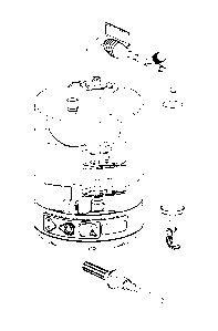
[00103] Turning first to Fig. 15, the applicant's method and device 1 in a
preferred
embodiment comprises a rigid disposable cartridge 10, which may hold up to 250
mL of liquid,
is cylindrical, single-use, and constructed preferably of hard plastic, and
more preferably
optically clear polycarbonate. The control module 40 in which the disposable
cartridge 10 is
seated is a battery operated, electro-mechanical device with optical and
gravitational sensing.
The preferred embodiment also comprises a membrane switch 41, a seven segment
digital read
out 42 and three light emitting diodes 43 to inform and assist the user. Shown
on the left in Fig.
15 is a universal battery sign 44 that alerts the user to the charge condition
of the battery. Shown
in the center is an on-off switch 45 for the control module and an LED, and on
the right is a
digital read out 42 and an LED that indicates whether the cell harvest run was
performed as
designed and, if not, which error in operation may have occurred.
[00104] Turning to Fig. 16, an exploded view of the disposable cartridge 10
and the
control module 40, as well as a standard 750 ml centrifuge cup70 is shown
according to the
preferred embodiment of the invention. In operation the disposable cartridge
10 and the
control module 40 are releasably locked together. The disposable cartridge
comprises
multiple compartments, one of which is the funnel or rigid chamber 11.
Preferably, the
centrifuge cup 70 houses the control module 40, which is intended for repeated
use with and
in connection with the sterile disposable cartridge 10 above it. The control
module 40 and
cartridge 10, in combination, preferably weigh approximately 450 grams. Among
other
CA 02793648 2012-09-18
WO 2011/116221 PCT/US2011/028863
17
components to be described later, the cartridge includes an inlet 12 at the
top that serves as
access for incoming fluid. This access may be connected to tubing which may
proceed to a
phlebotomy needle or a spike for connecting to a cell solution and may also be
coupled to an
inline filter that removes any clots that would otherwise jam other system
components during
the remaining processing steps. The top of the disposable cartridge may also
contain a 0.2-
micron filter 13 to provide passage for displaced air from within the funnel
when blood or
bone marrow is introduced into the funnel. The top of the cartridge may also
comprise a
means of sterile filtering (not shown) of the blood, bone marrow, or other
fluids such as
diluents, as they are introduced into funnel.
[00105] Turning to Fig. 17, the motor circuit board electronics 47, located
within the
lower control module 40 is shown. The electromechanical portion of the device
preferably
uses a rechargeable battery system to power a control module that monitors and
controls
gravitational and optical sensing equipment and directs activity in the
disposable cartridge.
The means for determining a G force may be any commonly known in the art, such
as
calculating said force through a measurement of centrifuge RPM, or through
direct
measurement of acceleration or force.
[00106] Fig. 18a shows a diagrammatic side view of the disposable cartridge 10
with
labeled cross section A-A. Fig. 18b shows a perspective view of the disposable
cartridge 10
cut along cross section A-A. As described in the process below, a biological
fluid
containing cells, such as normal blood, cord blood or bone marrow, is
delivered to the large
funnel-shaped compartment having an open end that is initially closed by a
valve means (not
shown). The cartridge comprises a large first rigid storage compartment or RBC
depletion
compartment 14 and the smaller second rigid storage compartment or SC
compartment 15
into which the WBCs and substantially all the SPCs are transferred. The RBC
depletion
compartment 14 is significantly larger than the SC harvest compartment 15, as
the volume of
RBCs depleted from a blood sample is always much greater that the volume of
WBCs
collected. All compartments are distinct from one another, but contiguous with
respect to
airflow. The RBC depletion compartment 14 and the SC harvest compartment 15
are
connected by small chimneys 29 to the original chamber so as to allow
displacement of air as
cell solutions move from the original chamber into the comparments.
[00107] Turning to Fig. 19, a perspective cross-sectional view of a disposable
cartridge 10
with a narrow bottom of the funnel 11 is shown. The larger RBC depletion
compartment 14
is seen in cross section on the left side of the funnel. As will be described
in detail below, in
operation, the RBCs initially migrate towards the bottom of the funnel shaped
primary
compartment, moving radially outward away from the axis of rotation of the
centrifuge until
CA 02793648 2012-09-18
WO 2011/116221 PCT/US2011/028863
18
reaching the valve system 16 at the bottom of the device. Here, the pressure
head of fluid
above the valve system urges the fluid into one of two compartments. Which
compartment
the fluid is directed into is dependent upon the status (open, closed) of
valves to those
compartments. In either case, after passing through the valve system 16 at the
bottom of the
cartridge 10, the fluid flows generally toward the axis of rotation, urged by
pressure from the
of fluid (mostly plasma) remaining in the primary compartment. The fluid that
has passed
through the valve system is then retained in either the RBC depletion
compartment 14 or the
SC harvest compartment 15. Through minute adjustments of the valves, unwanted
cell
solutions may be depleted and desired cell solutions may be harvested.
[00108] Turning to Fig. 20, a preferred embodiment of the present invention is
shown in
use. As shown, 100m1 of cord blood is placed inside the main funnel shaped
compartment
11. The operator then attached the cartridge 10 to the control module 40 (as
shown in Fig.
21), and then loads the cartridge into a centrifuge, preferably a swinging
bucket centrifuge,
such as a Thermo Fisher Sorvall ST-40 tabletop centrifuge configured to accept
four 750m1
cylindrical buckets. Alternative centrifuges may be used that provide for more
or less than
four cartridges to be centrifuged at once.
[00109] Turning to Fig.21, a representation of what occurs when the cartridge
10 is
subjected to high G forces is shown. Here, under an exemplary 2000 G
centrifugation the
RBCs begin to migrate down and the WBCs begin to migrate up from the bottom of
the
funnel and down from the top volume of the fluid to a position above the RBCs.
Above the
RBCs then, a very thin layer of WBCs and PLTs begins to stratify and above
that a volume
of plasma stratifies, the plasma is yellow in color. Under high G forces, the
RBCs are
increasingly squeezed together near the bottom of the processing funnel 11
with the heaviest
of the RBCs lower and the lighter RBCs near the top of the RBC volume. It is
noted that
because during centrifugation the cartridge depicted in the figure is rotating
about an axis
perpendicular to and located above the cartridge as shown, the G force
experienced by the
cartridge increases proportionally to the distance from the axis of rotation
and is roughly
twice as high at the bottom of the centrifuge cup (2000 Gs) as at the top
(1000 Gs).
[00110] Turning to Fig. 22, a detailed cut away side view of a preferred
embodiment is
shown. In this preferred embodiment the funnel 11 is kept separated from the
RBC depletion
compartment 14 and SC harvest compartment 15 by valve system 16. While many
means of
valve control are contemplated, in a preferred embodiment a pinch valve system
is used,
wherein eccentric cams 17 control tube pinchers 18 that ultimately direct flow
of liquid from
the bottom of the funnel to the cell depletion compartment 14 and to the cell
harvest
compartment 15. Here, the pinch valves comprise two opposing clamps having
pinching
CA 02793648 2012-09-18
WO 2011/116221 PCT/US2011/028863
19
surfaces approximately 0.088 inches wide, and require approximately 1.6 pounds
of pinching
force to block all fluid passage through a urethane tube with an inner
diameter of 0.062
inches and an exterior diameter of 0.088 inches when the hydraulic pressure in
the tube is at
325 PSI. Pinching forces in excess of 1.6 pounds may be required at greater
pressures, and
reduced pinching forces may be sufficient at lower pressures.
[00111] Turning to Fig. 23, a cantilever system to achieve these required
pinching
pressures is shown. The cantilever system 19 may open and close the valves
(pinch and
release the tubing) as needed. The springs 20 for each cantilever 21 are
preferably located at
the extreme end of the cantilever. The actuator overcomes the resistance of
the springs to
move the lever. Once the actuator stops applying force, the bias of the
springs urges the
lever back to its first position.
[00112] Turning to Fig. 24, a detailed view of the cam portion of the tube
pinching or
valve closing mechanism is shown. The cam converts rotational motion of a
valve motor
into a linear motion, which is used to close or pinch the tube. As disclosed
above, a cantilever
system may be employed in conjunction with the cam. As the cam 22 rotates
approximately
90 degrees clockwise, the larger portion of the cam exerts a continuing
clockwise torsional
force on the rotor and motor due to the high gravitational field exerting a
generally
downward force across the entire device. The cam is specially designed to
operate within an
extremely high gravitational field. The cutout 23 shown and the counterweight
24 located on
the opposite side of the cam allow the small motor to provide enough force to
rotate the cam
counterclockwise 90 degrees to its start position. The cam is thus
specifically designed to not
only reduce the amount of material off-axis and subjected to potentially
immobilizing
gravitational forces, but also to counter the weight of the remainder of the
cam in light of
such forces. That is, as the camshaft rotates about its central axis, this
design assures there is
no addition or subtraction of torque as a result of G forces acting on the
cam.
[00113] Fig. 25 shows the relative size of the various cells relative to the
connecting
tubing or flexible conduit (the large outer circle) of an exemplary
embodiment, which is
located between the primary compartment 11 and either the RBC depletion
compartment 14
or the SC harvest compartment 15. The tubing inner diameter in an exemplary
embodiment
is 0.062 inch (1.575 mm). Tubing of other inner and outer diameter may be
employed, so
long as complete cutoff of all cells and liquid is possible via a valve means.
In an exemplary
embodiment these flexible conduits have a ratio of length to diameter not
exceeding 20.
[00114] Returning to the description of the exemplary process, Fig. 26 shows
an
exemplary cartridge after approximately 10 minutes of centrifugation at 2000
Gs. The buffy
coat 2 stratifies at the interface between RBCs and plasma. The cells at the
very bottom of
CA 02793648 2012-09-18
WO 2011/116221 PCT/US2011/028863
the funnel 11 may reach an HCT (hematocrit, the proportion of blood volume
occupied by
red blood cells) approaching 90, but towards the top of the RBC layer the HCT
may be only
60-70, due to the lower centrifugation force at that distance from the axis of
rotation and the
wide area of the funnel at that location.
[00115] Turning to Fig. 27, a detailed view of the narrow region of the funnel
11 is
shown. When the disposable cartridge 10 is attached to the control module 40,
in this narrow
region of the primary compartment are at least one but preferably two or more
optical or
other sensors 48 that detect the type of cells flowing through that portion of
the processing
funnel. In this narrow region of the primary compartment are also at least one
but preferably
two or more optical or other emitters 49. In an exemplary embodiment shown
four infrared
emitters/detector pairs are arranged vertically. In a preferred embodiment
infrared sensors
are located directly across from paired infrared emitters. In second preferred
embodiment,
transmitters that provide wavelengths that are preferentially absorbed by red
cells are located
directly across from paired sensors sensitive to that frequency. In a third
preferred
embodiment sensors are utilized that identify cells that have absorbed
fluorescent dyes. In
the first preferred embodiment, the presence of cells interferes with the
emitted infrared light
and the infrared light detector quantifies the amplitude of the signal
penetrating the fluid. In a
preferred embodiment the sensors may assign the level of transmission a value
from 0-1000.
Pure plasma, which similar to water blocks none of the infrared light, will
register a value of
roughly 1000. As compacted RBCs pass, essentially all infrared light is
blocked and the
detector registers a value of 0.
[00116] Turning to Fig. 28, the next step in the process is shown. After a
sample has been
centrifuged for a set amount of time (20 minutes in an exemplary embodiment),
the
centrifuge may slow to a speed that creates 100 Gs at the bottom of the
centrifuge bucket
(that is, farthest from the axis of rotation). An on-board accelerometer may
track the G-force
throughout the process. Once the accelerometer detects that the centrifuge has
arrived at
100Gs, the device waits a set amount of time (in order to ensure the
centrifuge has settled at
100Gs and is not passing through to some lower G-force, such if the machine
had
malfunctioned or lost partial power), and then a first valve 25 connecting the
primary
compartment 11 with the RBC depletion compartment 14 opens, allowing passage
of highly
concentrated RBCs and some plasma. RBCs can be seen entering the depletion
compartment 14 by initially filling the standpipe 26 (which preferably has a
volume of lmL,
as will be described below). During use, the RBCs will continue to flow to
depletion
compartment 14 until the standpipe 26 is full, at which time the RBCs will
overflow and fill
the larger section of the depletion compartment 14.
CA 02793648 2012-09-18
WO 2011/116221 PCT/US2011/028863
21
[00117] Fig. 29 shows the standpipe 26 overflowing and the RBCs filling the
larger
depletion chamber. The interface between RBCs and plasma, delineated by the
buffy coat 2,
is now readily apparent. As the funnel 11 narrows, the same volume of cells
must occupy less
horizontal space. As a consequence, the vertical space occupied increases and
it becomes
easier to distinguish each stratified layer of cell types.
[00118] Turning to Fig. 30, the WBCs entering the narrow portion of the funnel
11 is
shown. As the WBCs enter this narrower portion, their stratification
continues, with the
GRNs on the bottom (not labeled), MNCs 3 in the middle, and PLTs 4 resting on
top of the
MNCs. The bulk of the plasma 5 in is shown above the PLTs.
[00119] The emitter/detector pairs, as shown in Fig. 27, monitor the passage
of the cells
through the narrow region of the primary compartment. Fig. 31 shows the
infrared optical
counts of blood cell populations during the 100 G transit from the l' position
(topmost)
emitter/detector pair. The horrizontal line represents the optical count
observed in cell-free
plasma. Lower optical counts signify that WBCs and PTLs are still present in
the sample
being observed by the emitted/detector pair. The initial rise from 0 at the
bottom left of the
graph indicates when the buffy coat layer disposed above the RBCs passes the
l' position
emitter/detector pair. The rising value indicates the solution passing between
the
emitter/detector pairs is becoming clearer, meaning it comprises fewer RBCs.
As the clearer
layers approach, the value increases, for instance to 50, then 100,200 and so
on.
[00120] Under some circumstances the optical count values that are shown in
Fig. 31 as
rising while cells are depleted, may, when the depletion is halted, begin to
fall, indicating that
more cells are entering the sensing area. The reasons for this are complex.
First, the optical
measurements are being taken through a fluid which experiences turbulence and
eddies as
particles of varying densities are reorganized as they are evacuated through
the bottom of a
funnel of decreasing radius. RBCs and WBCs fall at differing rates due to
their differing
sizes. Consequently, if the rate of evacuation of the RBCs is greater than the
sedimentation
rate for certain particles (such as the PLTs, small in size relative to the
others), then those
particles will lag behind other particles having faster sedimentation rates.
The carefully
stratified mixture becomes partially mixed during the evacuation process. Not
only do the
RBCs fall at one rate while the WBCs fall at a different rate, but also the
motion of the
WBCs may be inhibited by the motion of the vastly more numerous RBCs. Further,
the
density of RBCs changes throughout their lifecycle. Consequently, the lighter
RBCs will rise
with the displaced plasma as the more dense RBCs pack into the bottom of the
funnel. Thus
the WBCs that began at the bottom of the funnel and which rose towards the
RBC/plasma
interface are accompanied by the much more numerous "lighter" RBCs. These
ascending
CA 02793648 2012-09-18
WO 2011/116221 PCT/US2011/028863
22
cells maneuver around the descending dense RBCs due to the fact that all cells
possess a
slightly negative charge and so tend to repel one another.
[00121] To counter this mixing that inevitably occurs during depletion, the an
exemplary
embodiment of the system, after evacuating for a set time closes the tubing
through which the
cells are passing and allows the descending cells to re-compact and re-
stratify. Upon
reopening the tubing, mixing begins to occur again within the funnel. The
present invention
is thus able to employ a start-stop approach that periodically halts the
evacuation process,
should this mixing not be suitable for a given application.
[00122] Turning to Fig. 32, a latter point in the process is shown. At a
certain point in the
process the tube to the RBC depletion compartment 14 is closed, and the tube
to the SC
harvesting compartment 15 is opened. Fig. 32 depicts a later time in the
process wherein the
pathway to the SC harvest compartment 15 has been opened and the pathway to
the RBC
depletion compartment pinched shut. Because the RBC depletion compartment
standpipe 26
holds the final lmL of RBCs to enter the RBC depletion compartment 15, the
standpipe 26
contains the least dense of the RBCs, and hence a greater concentration of
GRNs and NRBCs
than does the RBC depletion compartment 15 as a whole. A technician may later
recover
the contents of the standpipe 26 and thus obtain GRNs and NRBCs for HLA typing
without
sacrificing the recovery of SPCs from the smaller SC compartment 15. As
centrifugation
continues, cells of greater density continue to be urged away from the axis of
rotation. The
plasma 5 remaining in the primary compartment continues to exert pressure on
the fluid and
cells beneath it, and drives the MNCs 3, and PLTs 4 up the tube leading to the
SC harvest
compartment 15. As shown, even after the MNCs and PLTs are largely removed
from the
primary compartment, plasma 5 is allowed to then flow into the SC harvest
compartment 15,
washing the connecting tube in the process and assuring that all SPCs are
collected in the
harvest compartment 15.
[00123] The timing for controlling the valve system 16 so fluid (and cells)
are directed to
the SC harvest compartment 15 as opposed to the RBC depletion compartment 14
is critical.
If the valves are switched too early, RBCs may enter the SC harvest
compartment 15, raising
the HCT and decreasing the purity of the sample collected. If the valves are
switched too
late, some of the MNCs may move to the RBC depletion compartment 14, thereby
reducing
the recovery of the MNCs and SPCs harvested.
[00124] One difficulty present in the prior art that is overcome by an
exemplary
embodiment of the present invention is the challenge of collecting a
predetermined final
volume of liquid transferred during centrifugation. This is important for
example because
various other types of equipment in which it is anticipated blood samples from
the current
CA 02793648 2012-09-18
WO 2011/116221 PCT/US2011/028863
23
invention will be used are configured to accept a predetermined volume of
liquid, such as
20mL. Although detecting when a certain volume of fluid has been collected
during
centrifugation is possible with specialized scales measuring the weight of the
fluid collected,
for reliability purposes a solid-state solution is preferred. To determine the
volume of liquid
passing through to the SC harvest compartment certain assumptions are
required. First, it is
known that the fluid above the cells passing through the sensor region of the
main
compartment is creating downward pressure on those cells and prompting their
evacuation
through the bottom of the funnel. As the liquid continues to be evacuated
under constant
acceleration, the rate of evacuation slows because there is less pressure on
those cells due to
the decreasing volume of plasma above them. It is also known that although
cell viscosity
may vary from hematocrit to hematocrit and person to person, plasma is
adequately
consistent with regard to viscosity. Consequently, once all the target cells
have passed and
only plasma remains to be transferred through the tubing to the SC compartment
it will flow
at a predictable rate proportionate to the dynamic head of plasma above it.
[00125] In the present invention, the above facts are coupled with a method
that employs
the multiple emitter/detector pairs passed by the evacuated cells. For
instance, as the buffy
coat approaches the top sensor, the optical count detected by the top, or 1st
position
emitter/detector pair, will begin to rise, as described above. An arbitrary
optical count value
(in this case 4) is predetermined and a timestamp is initiated when the l'
position
emitter/detector pair detects that arbitrary value. As evacuation continues, a
second
timestamp is set when the 2' position emitter/detector pair (that is, the pair
just under the
topmost pair) reads that same arbitrary value. Through calculations that take
into account the
distance between the 1st position and 2' position emitter/detector pairs, and
the time taken for
the arbitrary value to reach the 211d position, the velocity of blood
component flow between
the two pairs of sensors may be determined. The same process may be employed
to
determine the amount of time it takes any arbitrary value to pass from one
sensor to any other
sensor located beneath it.
[00126] With a further understanding of the volume of blood between sensors, a
rate of
volume depletion may be calculated. For instance, it is known that in one
embodiment of the
present invention the volume in the bottom tip of the funnel below the lst
position sensor is
6mL, while the volume below the second position sensor is 4mL. The rate of
flow can thus
be calculated based on the understanding that between the first time stamp and
the second
time stamp, 2mL of blood is evacuated. The rate may be further refined by
detecting when
the 31
1
position and 4th position (lowest) emitted/detector pair read that same
arbitrary value.
Importantly, during this process, the aforementioned start-stop technique is
taking place and
CA 02793648 2012-09-18
WO 2011/116221 PCT/US2011/028863
24
the effect of full valve closure on the rate of evacuation is noted. In
conclusion, through
extrapolation based on an observed rate of flow through stacked
emitter/detector pairs, a limit
can be set on the time that the valve to the SC harvest compartment is open as
the solution of
WBCs including the SPCs is topped up with plasma to a desired volume. The
limit varies
dependent on the rate of flow, which ultimately is predominately dependent on
the pressure
caused by the head of liquid above the evacuation point and, to some extent by
the viscosity
of the plasma that is used to "top up" the stem cell solution to a
predetermined final volume.
[00127] In alternative embodiments of the invention RBCs may be collected at
higher or
lower accelerations then the currently chosen 100 G, for instance in a
gravitational field of 50
to 200 Gs.
[00128] An alternative embodiment of the invention comprises a method to
significantly
reduce the number of PLTs 4 which are collected with the MNCs 5.
[00129] As is shown in Fig. 33, during the centrifugation process the MNCs 3
and
platelets 4 concentrate at the bottom narrow portion of the primary
compartment 11. At this
point in the process, if the pinch valve to the SC harvest compartment 15 were
opened, then
the MNCs would be urged by the mass of plasma in a direction first
perpendicular to the axis
of rotation and then up the right side tube towards the axis of rotation and
into the SC harvest
compartment 15. Without additional steps taken, the plasma would subsequently
force the
PLTs into the SC harvest compartment until they were depleted at which time
the flow of
plasma would top up the SC harvest compartment.
[00130] To reduce the number of PLTs that enter the SC harvest compartment 15,
the
technician may program the control module to pause the harvest process at the
end of the
RBC/GRN depletion cycle (by closing the RBC valve and not opening the MNC
valve) and
allow the centrifuge to come to a stop. In this method, the technician then
removes the
cartridge from the centrifuge bucket and gently rocks the cartridge in order
to redistribute
MNCs 3 and PLTs 4 throughout the plasma 5 in the funnel, dispersing them as
depicted in
Fig. 34.
[00131] As shown in Fig. 35, the cartridge is then centrifuged for a smaller
amount of
time and at a lower acceleration. The smaller amount of time and lower
acceleration is
sufficient to cause the denser and faster moving MNCs 3 to reconcentrate at
the bottom of the
funnel, but not enough to cause the PLTs to do the same. The PLTs are of lower
density and
size, and thus require more time to migrate to the bottom of the funnel. By
not providing that
time, the majority of the MNCs can be separated from the majority of the PLTs
as shown.
[00132] Turning to Fig. 36, when the pinch valve to the SC harvest compartment
15 is
then opened, the MNCs 3 flow first, followed by plasma 5 and a small fraction
of PLTs 4 and
CA 02793648 2012-09-18
WO 2011/116221 PCT/US2011/028863
then the SC harvest tubing is pinched closed. While some PLTs still make it
into the SC
harvest compartment, the fraction is proportional to the volume of plasma that
was
transferred into the SC harvest compartment compared to the total volume of
plasma in the
disposable cartridge. For example a 100 ml volume of blood would typically
contain about
55 ml of plasma. If 5 ml of plasma were transferred to the SC harvest
compartment, leaving
50 ml of plasma behind in the primary compartment, then the proportion of PLTs
with the
MNCs would be about 10% of the total PLTs---constituting a roughly 90%
reduction of
PLTs in the MNC harvest.
[00133] Turning to Fig. 37, another alternative embodiment is illustrated. In
this
alternative embodiment of the invention, GRNs 6 may be desired in the SC
harvest
compartment 15. For instance, in the collection of cord blood, the total WBC
count often
determines which of two cord blood units equally matched to the patient is
chosen.
Therefore it may be desired to include the majority of GRNs with the MNCs. To
obtain this
result, the technician may program the control module to open the valve to the
SC harvest
compartment earlier than in the other (above disclosed) embodiments, thereby
allowing the
top layer of RBCs (comprising many of the GRNs) into the harvest compartment.
It should
be readily apparent that through adjustments in timing, varying amounts of
GRNs may be
allowed into the SC harvest compartment. The sample collected in the harvest
compartment
is subsequently topped off with plasma so that the sample retains a relatively
low
(approximately 2-10 % hematocrit).
[00134] Turning to Fig. 38, in any of the above embodiments, mehanisms are in
place for
removing the contents of the SC harvest compartment as well as the standpipe
which
contains the last 1 mL of RBCs transferred to the RBC compartment. Fig. 38
shows the
disposable cartridge with both the SC harvest tube 27 and the RBC/GRN harvest
tube 28
deployed for collection. The RBC/GRN harvest tube connects to the exterior of
the cartridge
by any means known in the art, and creates a fluid connection with the bottom
of the
standpipe, thereby providing a simple means to retrieve NRBCs and GRNs from
the last 1
mL of the cell solution for sampling, such as obtaining human leukocyte
antigen (HLA)
typing, and then the remainder of the RBC/GRNs can also be removed, as
required.
[00135] In any embodiment of the present invention, it is to be understood
that antibody
beads, either bouyant in plasma or approximately as dense as RBCs, may be
introduced to
the sample prior to harvesting to bind to cells known to not be useful for a
specific research
or clinical purpose.
[00136] In any embodiment of the present invention, it should be readily
understood that
fluorescent material absorbable by certain cell populations may be introduced
to the sample
CA 02793648 2012-09-18
WO 2011/116221 PCT/US2011/028863
26
prior to harvesting to allow tracking of said cell populations through the
harvesting process
and thereafter.
[00137] Although the invention has been shown and described with respect to
certain
embodiments, it is obvious that equivalent alterations and modifications will
occur to others
skilled in the art upon the reading and understanding of the specification. In
particular, with
regard to the various functions performed by the above-described components,
the terms
(including any reference to a "means") used to describe such components are
intended to
correspond, unless otherwise indicated, to any component which performs the
specified
function of the described component (e.g., that is functionally equivalent)
even though not
structurally equivalent to the disclosed component which performs the
functions in the herein
exemplary embodiments of the invention. In addition, while a particular
feature of the
invention may have been disclosed with respect to only one embodiment, such
feature may
be combined with one or more other features of other embodiments as may be
desired or
advantageous for any given or particular application.