Note: Descriptions are shown in the official language in which they were submitted.
CA 02794670 2012-09-26
WO 2011/119691
PCT/US2011/029567
AIR FILTRATION DEVICE
SPECIFICATION
BACKGROUND OF THE INVENTION
1. FIELD OF INVENTION
This invention relates to devices and methods for the filtration of air. More
particularly,
this invention relates to air purifiers capable of providing a level of air
quality suitable for
environments that are highly sensitive to airborne contaminants, e.g., in
vitro fertilization
laboratories or other medical environments. Further, the invention may be
adapted for use in
any substantially enclosed environment, including, but not limited to, homes,
residential
buildings, commercial buildings, hotels, cars, buses, trains, airplanes,
cruise ships, educational
facilities, offices, and government buildings. The invention may also have
applications in, e.g.,
national security, defense, or airline industries.
2. DESCRIPTION OF RELATED ART
In vitro fertilization ("IVF') is a procedure whereby egg cells are fertilized
by sperm in a
laboratory environment, instead of in the womb. If an egg cell is successfully
fertilized, it may
be transferred into the uterus of a patient wishing to become pregnant.
IVF may be an effective option for patients suffering from infertility,
especially where
other methods of assisted reproduction have failed. However, IVF is very
expensive and is not
typically covered by medical insurance. In 2009, the cost of a single cycle of
IVF was
approximately $10,000 to $15,000 in the United States. It is financially
prohibitive for most
people to undergo multiple rounds of IVF. It is therefore imperative that
conditions for
successful pre-implantation embryogenesis are optimized, in order to maximize
the likelihood of
success.
One extremely important factor contributing to the likelihood of successful
pre-
implantation embryogenesis is the air quality of the IVF laboratory. Gametes
and embryos
grown in vitro are highly sensitive to environmental influences. Human embryos
have no means
of protection or filtration against environmental toxins and pathogens. They
are completely at
the mercy of their environment. The incubators which house the human embryos
often consist
of a significant percentage of room air. Although airborne contaminants can
adversely affect
embryogenesis, surprisingly little emphasis has been placed on optimizing
laboratory air quality
during the last three decades in which IVF has been available as a treatment
for infertility.
Existing filtration devices have been found insufficient to optimize air
quality to truly
acceptable levels for IVF. For example, it has been found that laboratory air
that had been
1
CA 02794670 2012-09-26
WO 2011/119691
PCT/US2011/029567
filtered with only high efficiency particulate air ("HEPA") filters was
actually of lesser quality
than outside air. Additionally, some filters produce by-products or other
contaminants that
actually detract from the quality of the air in an IVF laboratory. For
example, carbon filters can
create carbon dusting that is harmful to the IVF process. This is not to say,
however, that carbon
filters or HEPA filters should not be used to treat air supplied to an IVF
laboratory. On the
contrary, it is preferred that carbon filters, HEPA filters, or their
respective equivalents, are
included among filtration media used to treat air supplied to an IVF
laboratory. Attaining
optimal air quality in an IVF laboratory or other substantially enclosed space
requires proper
selection, combination and sequencing of various filtration media.
BRIEF SUMMARY OF THE INVENTION
Accordingly, an air purifier is provided. The air purifier includes a housing
with an inlet
for receiving air and an outlet for exhausting air. The housing provides an
air flow path for the
flow of air in a downstream direction, from the inlet towards the outlet.
Particulate pre-filtration
is located within the housing downstream from the air inlet. Volatile Organic
Compound
("VOC") pre-filtration is located within the housing downstream from the
particulate pre-
filtration. Ultra Violet ("UV") filtration is located within the housing
downstream from the
VOC pre-filtration. VOC post-filtration is located within the housing
downstream from the UV
filtration. Final particulate filtration is located within the housing
downstream from the VOC
post-filtration.
BRIEF DESCRIPTION OF SEVERAL VIEWS OF THE DRAWINGS
The invention will be described in conjunction with the following drawings in
which like
reference numerals designate like elements and wherein:
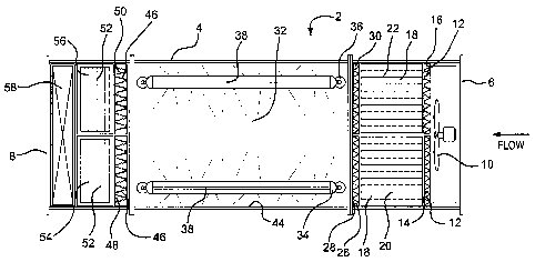
Fig. 1 is a top view of an air purifier according to the present invention.
Fig. 2 is a side view of an air purifier according to the present invention.
Fig. 3 is an internal view of the air purifier along the plane defined by
section line A - -
A of Fig. 1.
Fig. 4 is an internal view of the air purifier along the plane defined by
section line B - - B
of Fig. 2.
DETAILED DESCRIPTION OF THE INVENTION
Referring now in detail to the various figures of the drawings wherein like
reference
numerals refer to like parts, there are shown in Figs. 1 and 2 top and side
views, respectively, of
an air purifier 2 according to the present invention. As illustrated, the air
purifier 2 includes a
substantially rectangular cuboid housing 4 having an inlet 6 for receiving air
and an outlet 8 for
2
CA 02794670 2015-04-21
exhausting air. The term "air" as used herein broadly refers to a gas or
gaseous mixture that may
be safely breathed by mammals and/or that can serve as a source gas or gaseous
mixture towards
an IVF laboratory. The housing 4 provides an air flow path for the flow of air
in a downstream
direction, i.e., from the inlet 6 towards the outlet 8. The term "housing" as
used herein refers to
any conduit, chamber and/or enclosure, or a plurality of conduits, chambers
and/or enclosures
coupled to one another, providing an air flow path within. Thus, the "housing"
could include,
e.g., ductwork of an existing heating, ventilating and air conditioning
("HVAC") system or air
handling unit ("AHU").
Although the housing 4 is preferably substantially rectangular cuboid, as
shown in Figs.
1 and 2, it need not be limited to any particular shape. Moreover, it may
include inner curves,
bends and/or other contours, whereby the air flow path would follow such
curves, bends and/or
other contours. Preferably, however, the air flow path is substantially
straight, as it is in the
embodiment of the housing 4 shown in Figs. 1 and 2.
The air purifier 2 is preferably adapted to be installed into an existing HVAC
system or
AHU. In an alternative embodiment, an air purifier according to the present
invention may
function as a stand-alone unit, i.e., one that is not part of an HVAC system
or AHU. An
exemplary housing 4 may be a substantially rectangular cuboid having
dimensions of
approximately 11 ft. long by 4 ft. wide by 2 ft. high. Such dimensions would
diffuse or spread
out the air through the air purifier 2 so as to provide sufficient residence
time for the air through
each of the filtration media discussed infra. A skilled artisan understands,
however, that the
foregoing exemplary shape and size parameters are merely illustrative, and may
be changed,
even substantially, depending on the circumstances or application. For
example, in some
applications, the air purifier 2 may be about 6 ft. long.
Referring now to Fig. 3, there is shown an internal view of the air purifier 2
along the
plane defined by section line A - - A of Fig. 1. In Fig. 4, there is shown an
internal view of the
air purifier 2 along the plane defined by section line B - - B of Fig. 2.
To obtain optimal air quality, e.g., suitable for an IVF laboratory, the air
that is treated by
the air purifier 2 should be pre-conditioned and stable, i.e., moderate both
in terms of
temperature and humidity. Ideally, the air that is treated by the air purifier
2 should have a
temperature of between about 68 F and 75 F, and a humidity of between about
45% and 55%.
Additionally, the air flow rate through the air purifier 2 should preferably
be about 250 ft./min.
and below 2000 CFM. This preferred flow rate is intended to provide sufficient
residence time
for the air through each of the filtration media discussed infra. The term
"filtration" as used
3
CA 02794670 2012-09-26
WO 2011/119691
PCT/US2011/029567
herein, broadly covers one or more devices that treat air, such as by
trapping, removing,
deactivating and/or destroying contaminants therefrom.
In order to provide an adequate air flow rate through the air purifier 2, it
may be helpful
(although not always necessary) to include a booster fan 10 downstream from
the inlet 6. The
booster fan 10 may be coupled to a control system (not shown) that measures
the air flow rate
and triggers the booster fan 10 as needed, to maintain the desired air flow
rate. In an alternative
embodiment (not shown), a booster fan may not be included, and adequate air
flow rate may be
provided and maintained by other means, e.g., a blower in an HVAC system or
AHU into which
the air purifier 2 is installed.
Downstream from the inlet 6 is particulate pre-filtration 12 for the trapping
of airborne
particulate. The particulate pre-filtration 12 is preferably about 2 inches
thick in one
embodiment, and includes left and right pleated particulate pre-filters 14,16.
The particulate
pre-filters 14,16 trap gross particulate (e.g., dust and bugs) from the
outside air before that air
reaches the other filtration media in the air purifier 2 discussed infra.
Suitable filters for the
particulate pre-filtration 12 are those having a Minimum Efficiency Reporting
Value ("MERV")
of 5 to 13 with an Average ASHRAE Dust Spot Efficiency (Standard 52.1) of 20%
to 80%.
Particularly preferred filters for the particulate pre-filtration 12 are
pleated filters having a
MERV of 7 to 8, with an Average ASHRAE Dust Spot Efficiency (Standard 52.1) of
30% to
45%.
Proper particulate pre-filter selection should be guided by the need to trap
gross-
particulate without unduly affecting the air flow rate through the air
purifier 2. The particular
type of particulate pre-filter(s) selected for particulate pre-filtration
depends on various factors,
including outside air quality. It is preferred that the particulate pre-
filtration 12 is located
immediately upstream from the additional filtration media discussed infra, as
shown in Figs. 3
and 4. Alternatively (or in addition), however, particulate pre-filtration may
be located further
upstream, e.g., in upstream ductwork of an HVAC system or AHU into which the
air purifier 2
is installed.
Downstream from the particulate pre-filtration 12 is volatile organic compound
("VOC")
pre-filtration 18. Once air passes through the particulate pre-filtration 12,
the air is effectively
free of gross particulate that would otherwise diminish the efficacy and
useful life of the VOC
pre-filtration 18. VOC pre-filtration ideally includes adsorption media, such
as carbon, as well
as oxidation media, such as potassium permanganate ("KWIn04") or a
photocatalytic oxidizer.
A particularly preferred type of carbon is virgin coconut shell. In a
preferred embodiment, the
4
CA 02794670 2012-09-26
WO 2011/119691
PCT/US2011/029567
VOC pre-filtration 18 is a carbon and KMn04 blend, e.g., in a 50/50
proportion. In some
embodiments, the blend may include additional elements, such as natural
zeolite. The
proportion of the blend may vary depending on the types and levels of VOCs
present in the
source air. Ideally, the source air would be tested for VOCs, and, based on
test results, a custom
blend would be prepared to maximize VOC removal in a given environment. In an
alternative
embodiment of the VOC pre-filtration (not shown), separate (i.e., non-blended)
carbon and
KMn04 filters are used.
The embodiment of the VOC pre-filtration 18 shown in Figs. 3 and 4 includes a
total of
twenty stacked filter trays 20,22, whereby ten such trays 20 are on the left
side of the housing 4
and ten such trays 22 are directly adjacent, to the right. The length of the
trays, i.e., the
longitudinal distance over which the air flows, is preferably about 17 inches
in one embodiment,
though it may be shorter or longer. Each tray 20,22 includes two blended
carbon and KMn04
filters 24, arranged in a V-bank along a vertical plane (e.g., the plane of
Fig. 3). The V-bank
arrangement increases the surface area of the filters 24 over which air must
travel, thereby
enhancing the effectiveness of the VOC pre-filtration 18. Once air passes
through the VOC pre-
filtration 18, the VOC load of the air is effectively reduced.
Downstream from the VOC pre-filtration 18 is particulate post-filtration 26
for the
trapping of airborne particulate, e.g., particulate generated by the VOC pre-
filtration 18 (such as
carbon dusting). The particulate post-filtration 26 includes left and right
pleated particulate
post-filters 28,30. The filters used in the particulate post-filtration 26 may
be identical or similar
to those used in the particulate pre-filtration 12, discussed supra. While
particulate post
filtration 26 downstream from the VOC pre-filtration 18 is preferred, it may
not be necessary in
all applications. For example, if the VOC pre-filtration is of a type that
does not generate air-
borne particulate, such as bonded carbon, particulate post-filtration may be
optional.
Downstream from the particulate post-filtration 26 is ultraviolet ("UV")
filtration 32
which destroys airborne biological contaminants and, in some embodiments,
degrades chemical
contaminants. Whether or not particulate post-filtration 26 is used, the air
reaching the UV
filtration 32 should be effectively free of gross particulate and contain
dramatically reduced
levels of VOCs so as not to diminish the efficacy of the UV filtration 32.
The UV filtration may include one or more UV sources, although a plurality of
UV
sources is preferred. It is further preferred that these UV sources are UVC
sources, capable of
generating UV radiation at a wavelength varying from 220 nm to 288 nm. Most
preferably, the
UVC sources are capable of generating UV radiation at a wavelength of 260 nm,
however
5
CA 02794670 2015-04-21
commercially available UVC sources capable of generating UV radiation at a
wavelength of 254
nm are adequate. In an alternative embodiment described in U.S. Pat. No.
5,833,740 (Brais), the
UV filtration includes at least one vacuum UV source, capable of generating UV
radiation at a
wavelength varying from 170 nm to 220 nm (preferably 185 nm) and at least one
UVC source,
capable of generating UV radiation at a wavelength varying from 220 nm to 288
nm (preferably
260 nm). In that embodiment, the UVC source is preferably downstream from the
vacuum UV
source. When operating, the vacuum UV source breaks oxygen molecules into mono-
atomic
oxygen which then reacts with chemical contaminants present in the air and
then degrades them
by successive oxidation to odorless and inoffensive byproducts. The UVC source
kills
biological contaminants present in the air by irradiation and degrades
residual ozone produced
by the vacuum UV source into molecular oxygen.
Particularly preferred UV filtration 32 shown in Figs. 3 and 4 is the "UV
Biowa11TM"
made by Sanuvox. Alternatively, the "Bio 30GX," which is also made by Sanuvox,
is a
preferred type of UV filtration. The UV filtration 32 includes a pair of
fixtures 34,36 each of
which has five UV lamps 38 (not all five of which are visible in the Figures).
The UV lamps 38
are preferably about 60 inches long and extend longitudinally through the
housing 4 so as to
maximize exposure time of the air to UV radiation. In one embodiment, the UV
lamps are UVC
sources, providing UV radiation within the UVC wavelength parameters discussed
supra. In an
alternative embodiment, described in U.S. Pat. No. 5,833,740 (Brais), each
lamp 38 is dual-
zoned, having an upstream vacuum UV source and a downstream UVC source. In
that
alternative embodiment, the upstream vacuum UV source may, e.g., be a high
intensity mercury
vapor lamp capable of generating UV radiation having a wavelength in a range
of about 170 nm
to about 220 nm, and the downstream UVC source may, e.g., be a low intensity
mercury vapor
lamp capable of generating radiation having a wavelength in a range of about
220 nm to about
288 nm. The interior 44 of the housing 4 encasing thc UV filtration 32 is
highly reflective, with
a preferable coefficient of reflection of at least 60%, so as to enhance the
effectiveness of the
lamps 38.
The kill rate of biological contaminants is a function of the intensity of UVC
radiation
produced by the UV filtration 32 and reflected by the interior 44 of the
housing 4, as well as the
exposure time of such contaminants to the UVC radiation. Thus, the higher the
intensity of the
UVC radiation and the longer the exposure time of such contaminants to the UVC
radiation, the
greater is the level of sterilization achieved. Depending on factors such as
the desired level of
6
CA 02794670 2012-09-26
WO 2011/119691
PCT/US2011/029567
sterilization, the amount of space available to house UV filtration, and costs
of operating and
maintaining UV filtration, the desired total UVC output of the UV filtration
32 may vary. In one
actual embodiment, it was found that a total UVC output ranging from about
33,464 P/cm2 to
about 90,165 Pcm2, with an average total UVC output of about 43,771 RJ/cm2,
provided a
desired level of sterilization, given practical constraints of cost and space.
Such total UVC
output killed 100% of numerous biological contaminants including, but not
limited to smallpox,
flu, tuberculosis, anthrax and H1N1 virus.
The UV filtration 32 contained within the housing 4 is likely not visible to a
user of the
air purifier 2 when in use, because direct UV exposure is harmful to humans.
Thus, a user
cannot ascertain visually (i.e., by simply looking at the air purifier 2
itself) whether the lamps 38
are operating at a given time. It cannot be assumed that the air purifier 2 is
effectively
destroying air-borne biological and chemical contaminants, without knowing for
sure that the
UV filtration is operating properly. Accordingly, it is preferred that the
present invention
include sensors and a monitor (not shown) to detect and indicate,
respectively, how much time
each UV lamp 38 has been in use and whether each lamp 38 is operating at a
given time. The
monitor may include, e.g., a scrolling digital clock, which indicates the
length of time each lamp
38 has been operating. These sensors and monitor would indicate to a user when
it is time to
replace any of the lamps 38.
As a general matter, moisture within the housing 4 can foster the growth of
biological
contaminants. Accordingly, it is preferable to include a UVC source in the
vicinity of areas in
which moisture is generated or gathers. For example, upstream from the
particulate pre-
filtration 12 may be one or more cooling coils (not shown) that help to ensure
that the air which
is treated by the air purifier 2 is moderate in terms of temperature. Such
cooling coils tend to
generate moisture. It is therefore preferable to include a UVC source adjacent
to such cooling
coils. Similarly, it may be appropriate to include a UVC source immediately
upstream from a
filter/diffuser (not shown) from which the air enters into a substantially
enclosed space, e.g., an
IVF laboratory or other room, after leaving the air purifier 2.
Downstream from the UV filtration 32 is VOC post-filtration 46, which capture,
e.g.,
VOC by-products of the irradiation from the UV filtration 32. Possible
embodiments of the
VOC post-filtration 46 include any of those discussed supra regarding the VOC
pre-filtration
18. The VOC post-filtration 46 shown in Figs. 3 and 4 includes left and right
VOC post-filters
48,50 that are arranged in a V-bank along a horizontal plane (e.g., the plane
of Fig. 4). The
VOC post-filters 48,50, like their upstream counterparts, are preferably
blended carbon and
7
CA 02794670 2012-09-26
WO 2011/119691
PCT/US2011/029567
KMn04. Although VOC post-filtration 46 is preferred, in some applications, it
may not be
required and may thus be omitted.
Gametes and the human embryo are highly sensitive to VOCs, even in amounts
considered negligible in other applications. It is therefore essential that
the VOC filtration (both
pre-filtration 18 and post-filtration 46) operates effectively to remove VOCs
from air that is fed
into an environment in which IVF is being conducted. Accordingly, one or more
sensors for
detecting VOC levels (not shown), preferably in real time, may be placed in an
IVF laboratory
and coupled to a monitor (not shown) to indicate the VOC levels in the
laboratory at a given
time. With such in-room VOC detection, a user of the air purifier 2 would know
when it is time
to replace the VOC pre-filtration 18 and post filtration 46, and/or whether an
alternative type or
blend of VOC filters would be more suitable. While in-room VOC detection is
particularly
useful in an IVF laboratory, it may be helpful in any environment requiring
low VOC levels.
Downstream from the VOC post-filtration 46 is final particulate filtration 52,
which
traps substantially all remaining particulate in the air before the air exits
the outlet 8. Final
particulate filtration 52 preferably includes one or more filters capable of
trapping fine airborne
particulate, e.g., filters having a MERV of 13 or greater with an average
ASHRAE Dust Spot
Efficiency (Std. 52.1) of 80% or greater. More preferably, such filters have a
MERV of 16 or
greater with an average ASHRAE Dust Spot Efficiency (Std. 52.1) of 95% or
greater. Most
preferably, such filters have a MERV of 17 or greater with an average ASHRAE
Dust Spot
Efficiency (Std. 52.1) of 99.97%, as do high efficiency particulate air
("HEPA") filters.
Alternatively, ultra low particulate air ("ULPA") filters may be suitable. The
choice of filter(s)
for final particulate filtration should be guided by the potentially competing
needs of
maintaining an optimal air flow rate and effectively removing particulate from
the air.
The final particulate filtration 52 of Figs. 3 and 4 includes left and right
12-inch thick
HEPA filters 54,56. Preferably, magnehelic gauges (not shown) are placed both
upstream and
downstream from the HEPA filters 54, 56 to measure the pressure drop across
those filters. The
degree of pressure drop will assist in the identification of the proper time
in which to change the
HEPA filters 54,56, or other filters used for final particulate filtration.
Downstream from the final particulate filtration 52, is an atomizing
humidifier 58. The
humidifier 58 may or may not be necessary, depending on the needs of the
facility in which the
air purifier 2 is being used. However, if a humidifier 52 is needed, it should
be placed
downstream from the final particulate filtration 52 so that the moisture does
not adversely affect
the performance of the VOC post-filters 48,50, the HEPA filters 54,56, or
other filters used for
8
CA 02794670 2014-10-21
Attorney Docket W1148/20002
final particulate filtration. Humidified air can contain and support the
growth of biological
contaminants. Accordingly, if a humidifier 58 is used, an additional UVC
source (not shown) to
destroy such contaminants should also be included. This additional UVC source
should be
downstream from the humidifier 58, preferably at the last point in ductwork
before entry into a
room served by the purified air.
An air purifier according to the present invention, such as that described in
detail, supra,
will produce optimal air quality, suitable for airborne contaminant-sensitive
environments such
as IVF laboratories or other medical environments, for example. That said, an
air purifier
according to the present invention is not limited to IVF or other medical
applications. It may be
adapted for use in any substantially enclosed environment, including, but not
limited to, homes,
residential buildings, commercial buildings, hotels, cars, buses, trains,
airplanes, cruise ships,
educational facilities, offices, and government buildings. The invention may
also have
applications in, e.g., national security, defense, or airline industries. The
sequence and type of
air filtration media in an air purifier according to the present invention
provides air having a
quality that was unattainable with prior devices.
While the invention has been described in detail and with reference to
specific examples
thereof, it will be apparent to one skilled in the art that various changes
and modifications can be
made therein without departing from the scope thereof.
9