Language selection

Search

Patent 2794698 Summary

Third-party information liability

Some of the information on this Web page has been provided by external sources. The Government of Canada is not responsible for the accuracy, reliability or currency of the information supplied by external sources. Users wishing to rely upon this information should consult directly with the source of the information. Content provided by external sources is not subject to official languages, privacy and accessibility requirements.

Claims and Abstract availability

Any discrepancies in the text and image of the Claims and Abstract are due to differing posting times. Text of the Claims and Abstract are posted:

  • At the time the application is open to public inspection;
  • At the time of issue of the patent (grant).
(12) Patent: (11) CA 2794698
(54) English Title: PORTABLE VIBRATION SPEAKER
(54) French Title: HAUT-PARLEUR A VIBRATIONS PORTATIF
Status: Expired and beyond the Period of Reversal
Bibliographic Data
(51) International Patent Classification (IPC):
  • H04R 11/02 (2006.01)
  • H04R 01/02 (2006.01)
  • H04R 03/00 (2006.01)
(72) Inventors :
  • MEI, QINGKAI (China)
(73) Owners :
  • QINGKAI MEI
(71) Applicants :
  • QINGKAI MEI (China)
(74) Agent:
(74) Associate agent:
(45) Issued: 2016-06-21
(86) PCT Filing Date: 2011-10-20
(87) Open to Public Inspection: 2012-12-22
Examination requested: 2012-08-22
Availability of licence: N/A
Dedicated to the Public: N/A
(25) Language of filing: English

Patent Cooperation Treaty (PCT): Yes
(86) PCT Filing Number: PCT/CN2011/081051
(87) International Publication Number: CN2011081051
(85) National Entry: 2012-08-22

(30) Application Priority Data:
Application No. Country/Territory Date
201110173735.0 (China) 2011-06-22

Abstracts

English Abstract


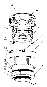
The invention discloses a kind of portable vibration speaker that is composed
of an upper cover, a lower cover, and a vibrating tone generator and a control
circuit
(the both are fitted inside the lower cover). The inside of the upper cover is
fitted with
a speaker. The improvements include a blow-molded spring; one end of the blow-
molded
spring is connected to the upper cover, and the other end is connected to the
lower cover in rotating mode; inner wall of the upper cover is provided with a
buckle,
and a buckle flute is arranged in a position on the lower cover corresponding
to the
buckle. A blow-molded spring connects the resonant sound unit and speakers
into
one piece so as to avoid the flaws such as poor sound effects and narrow
volume
range of pure resonant sound unit or conventional compact sound unit. Music of
different sound quality may be given with superior sound quality effects. The
portable
vibration speaker is characterized by its compactness, handiness and superior
bass
effects, and may meet the needs of young consumers.


Claims

Note: Claims are shown in the official language in which they were submitted.


CLAIMS
What is claimed is:
1. A portable vibration speaker comprising an upper cover, a lower cover, a
vibrating
tone generator and a control circuit; the vibrating tone generator and the
control
circuit are fitted inside the lower cover; a speaker is fitted inside the
upper cover,
wherein the portable vibration speaker also comprises a blow-molded spring;
one
end of the blow-molded spring is connected to the upper cover, and another end
of
the blow-molded spring is rotatably connected to the lower cover; inner wall
of the
upper cover is provided with buckles, and buckle flutes are arranged in
positions on
the lower cover corresponding to the buckles; the vibrating tone generator
comprises
a pedestal, a magnet and a surround coil; an upper end and a lower end of the
pedestal are provided with a first vibration transferring body and a second
vibration
transferring body respectively; the first and the second vibration
transferring bodies
are capable of moving up-and-down relative to the pedestal; the first
vibration
transferring body is connected to a coil sleeve on which the surround coil is
fitted; the
magnet is fitted inside the coil sleeve, and a magnetizer is fitted over the
magnet.
2. The portable vibration speaker as claimed in Claim 1, characterized in that
the
lower cover is provided with an audio input interlace, power supply interface
and
switch, which are connected to a control circuit board.
3. The portable vibration speaker as claimed in Claim 1, characterized in that
the
second vibration transferring body extends out of the lower cover.
4. The portable vibration speaker as claimed in Claim 1, characterized in that
the
second vibration transferring body is provided with a rubber pad.
5. The portable vibration speaker as claimed in Claim 1, characterized in that
the
upper cover is provided with a sound hole.
7

Description

Note: Descriptions are shown in the official language in which they were submitted.


CA 02794698 2012-08-22
DESCRIPTION
TITLE OF THE INVENTION
Portable Vibration Speaker
TECHNICAL FIELD OF THE INVENTION
The invention is related to acoustics, especially a kind of portable vibration
speaker.
BACKGROUND OF THE INVENTION
In recent years, a kind of resonant sound unit goes on the market, which
overturns people's concept and understanding of conventional sound unit. The
sounding system of this kind of resonant sound unit is not provided with
vibrating
diaphragms; however, it may convert the audio signals into audio mechanical
vibration as per the principle of resonance, and output the audio mechanical
vibration to any hard objects touched by it, such that the hard objects may
serve as
sounding media; the sounds are delicate, even, free of directivity, and may be
spread in omni-directional mode (3600). Surround sound may be obtained, and
various tone quality effects may be attained by different sounding media. The
resonant sound unit is characterized by its compactness, and may be placed at
your
own sweet will. It may change the common hard objects such as tables, doors,
windows and floor board into natural sound unit only if it is connected to the
tone
source equipment like computer, MP3, MP4, MD, CD, or DVD player. However, the
resonant sound unit developed as per the existing technologies is not combined
with
a loudspeaker system. The existing resonant sound unit works as simple
resonant
sound unit that features a relatively narrow volume range, poorly presented
treble,
and some flaws. Furthermore, the bass effect of conventional compact sound
unit is
t

CA 02794698 2012-08-22
usually poor due to its small chambers, its sound quality is non-tunable, and
its
overall sound effects may not satisfy most of the young consumers.
BRIEF SUMMARY OF THE INVENTION
The invention is intended to provide a kind of portable vibration speaker
that may effectively overcome the above-mentioned shortages and is provided
with a
wide volume range and better sound effects.
Technical proposal of the invention is implemented in this way: It is
composed of an upper cover, a lower cover, and a vibrating tone generator and
a
control circuit (the both are fitted inside the lower cover). The inside of
the upper
cover is fitted with a speaker. The improvements also include a blow-molded
spring;
one end of the blow-molded spring is connected to the upper cover, and the
other
end is connected to the lower cover in rotating mode; inner wall of the upper
cover is
provided with a buckle, and a buckle flute is arranged in a position on the
lower
cover corresponding to the buckle;
In the above-mentioned structure, the vibrating tone generator is
composed of a pedestal, a magnet and a surround coil. The upper end and lower
end of the pedestal are provided with 1 b` vibration transferring body and 2rd
vibration
transferring body respectively. The both resonance transferring bodies may
carry out
up-and-down movement relative to the pedestal. The 15t vibration transferring
body is
connected to a coil sleeve on which a surround coil is fitted. The magnet is
fitted
inside the coil sleeve, and a magnetizer is fitted over the magnet;
In the above-mentioned structure, the lower cover is provided with an
audio input interface, power supply interface and switch, which are connected
to the
control circuit board;
2

CA 02794698 2012-08-22
In the above-mentioned structure, the 2nd vibration transferring body
extends out of the lower cover;
In the above-mentioned structure, the 2nd vibration transferring body is
provided with a rubber pad;
In the above-mentioned structure, the upper cover is provided with a
sound hole.
Advantageous effects of the invention include the following: Firstly, in the
portable vibration speaker of the invention, a blow-molded spring connects the
resonant sound unit and speakers into one piece so as to avoid the flaws such
as
poor sound effects and narrow volume range of pure resonant sound unit or
conventional compact sound unit. Its vibrating tone generator is provided with
1S'
vibration transferring body and 2nd vibration transferring body. Prior to
operation,
connect the audio input terminal of the portable vibration speaker to the tone
source
equipment, and connect the electric power supply to the power supply
interface. The
varying music signals are processed by the control circuit board, and enter
into the
surround coil such that the surround coil generates a varying magnetic field.
Under
the action of the varying magnetic field, 1 S' vibration transferring body and
2nd
vibration transferring body start vibrating. Music of different sound quality
may be
given once the vibrational energy is transferred to the surface of a hard
medium; the
music features superior sound quality effects, and the user may enjoy the
music that
makes for comfort as much as he likes. Secondly, in the above-mentioned
structure
of the invention, 2nd vibration transferring body is provided with a rubber
pad that
may effectively avoid the noises generated during vibration so as to improve
the
sound effects further. Thirdly, prior to operation, the blow-molded spring may
be
compressed such that the upper cover and lower cover may be fastened with a
3

CA 02794698 2012-08-22
buckle; in such a case, the equipment may be used as an ordinary sound unit
more
freely. Fourthly, the portable vibration speaker features compactness,
handiness and
superior bass effect, and may meet the needs of young consumers.
BRIEF DESCRIPTION OF THE DRAWINGS
Fig. 1 shows an exploded view of the invention;
Fig. 2 shows a structural representation of the invention with its upper
cover and lower cover opened;
Fig. 3 shows a structural representation of the invention with its upper
cover and lower cover buckled;
In the figures: 1 Upper cover, 2 Lower cover, 3 Vibrating tone generator, 4
Speaker, 5 Blow-molded spring, 6 Buckle, 7 Buckle flute, 8 Pedestal, 9
Surround coil,
1st vibration transferring body, 11 2nd vibration transferring body, 12 Rubber
pad,
13 Power supply interface, 14 Switch, 15 Audio input interface, 16 Sound hole,
17
Coil sleeve.
DETAILED DESCRIPTION OF THE INVENTION
The invention is further described as per the figures and embodiments.
As shown in Figs. 1 to 3, the invention is a kind of portable vibration
speaker. It is composed of upper cover 1, lower cover 2, blow-molded spring 5
and
vibrating tone generator 3 and control circuit board fitted inside lower cover
2. The
inside of upper cover 1 is fitted with speaker 4. Therein, one end of blow-
molded
spring 5 is connected to upper cover 1, and the other end is connected to
lower
cover 2 in rotating mode. The blow-molded spring 5 may be rotated for a
certain
angle relative to lower cover 2. The inner wall of upper cover 1 is provided
with
buckle 6, and buckle flute 7 is arranged in a position corresponding to buckle
6 in
lower cover 2. Upper cover 1 may be pushed downward such that blow-molded
4

CA 02794698 2012-08-22
spring 5 may be compressed; then rotate upper cover 1 for a certain angle, and
have
buckle 6 on inner wall of upper cover 1 and buckle flute 7 in lower cover 2
fastened
such that upper cover 1 and lower cover 2 are buckled (as shown in Fig. 3);
when
the portable vibration speaker is used in such a "buckled" state, its effect
is
equivalent to ordinary sound unit that is free of obvious resonant effects.
In the above-mentioned structure, the vibrating tone generator 3 is
composed of pedestal 8, magnet (not shown in the figure), and surround coil 9.
The
upper end and lower end of pedestal 8 are provided with 1St vibration
transferring
body 10 and 2nd vibration transferring body 11 respectively. The both
resonance
transferring bodies may carry out up-and-down movement relative to pedestal 8.
The
1St vibration transferring body 10 is connected to coil sleeve 17 on which 17
surround
coil 9 is fitted. The magnet is fitted inside coil sleeve 17, and a magnetizer
(not
shown in the figure) is fitted over the magnet. The 2nd vibration transferring
body 11
extends out of lower cover 2; 2nd vibration transferring body 11 is provided
with
rubber pad 12 that may effectively avoid the noises generated during vibration
so as
to improve the sound effects further. Moreover, lower cover 2 is provided with
audio
input interface 15, power supply interface 13 and switch 14, which are
connected to
the control circuit board; upper cover 1 is provided with sound hole 16.
In order to improve the operational stability, the axes of upper cover 1,
lower cover 2, magnet fitted inside vibrating tone generator 3, pedestal 2,
1st
vibration transferring body 10 and 2nd vibration transferring body 11 coincide
with
each other.
Prior to operation, in order to attain a perfect resonant effect, rotate upper
cover 1 for a certain angle to release the buckled state of upper cover 1 and
lower
cover 2 such that upper cover 1 and lower cover 2 may be kept open by blow-

CA 02794698 2012-08-22
molded spring 5 (as shown in Fig. 2). Connect audio input terminal 15 of the
portable
vibration speaker to tone source equipment, connect an electric power supply
to
power supply interface 13. The varying music signals are processed by the
control
circuit board, enter into surround coil 9 such that surround coil 9 generates
a varying
magnetic field. Under the action of the varying magnetic field, 1st vibration
transferring body 10 and 2nd vibration transferring body 11 start vibrating.
Music of
different sound quality may be given once the vibrational energy is
transferred to the
surface of a hard medium; the music features superior sound quality effects,
and the
user may enjoy the music that makes for comfort as much as he likes.
Only the preferred embodiments of the invention are described above, and
the above-mentioned specific embodiments are not intended to restrict the
invention.
Many modifications and variations of the present invention will be apparent to
one of
ordinary skill in the art in light of the teachings of this invention. All
retouches,
modifications or equipollent replacements performed by ordinary technicians of
the
art in accordance with the above-mentioned description fall within the scope
of
protection of the invention.
6

Representative Drawing
A single figure which represents the drawing illustrating the invention.
Administrative Status

2024-08-01:As part of the Next Generation Patents (NGP) transition, the Canadian Patents Database (CPD) now contains a more detailed Event History, which replicates the Event Log of our new back-office solution.

Please note that "Inactive:" events refers to events no longer in use in our new back-office solution.

For a clearer understanding of the status of the application/patent presented on this page, the site Disclaimer , as well as the definitions for Patent , Event History , Maintenance Fee  and Payment History  should be consulted.

Event History

Description Date
Time Limit for Reversal Expired 2017-10-20
Letter Sent 2016-10-20
Grant by Issuance 2016-06-21
Inactive: Cover page published 2016-06-20
Inactive: Final fee received 2016-04-07
Pre-grant 2016-04-07
Notice of Allowance is Issued 2016-03-18
Letter Sent 2016-03-18
Notice of Allowance is Issued 2016-03-18
Inactive: QS passed 2016-03-16
Inactive: Approved for allowance (AFA) 2016-03-16
Amendment Received - Voluntary Amendment 2015-09-24
Maintenance Request Received 2015-09-22
Inactive: S.30(2) Rules - Examiner requisition 2015-06-18
Inactive: Report - No QC 2015-06-10
Amendment Received - Voluntary Amendment 2014-12-23
Maintenance Request Received 2014-10-20
Inactive: S.30(2) Rules - Examiner requisition 2014-07-03
Inactive: Report - No QC 2014-06-17
Maintenance Request Received 2013-10-02
Inactive: Cover page published 2013-01-18
Application Published (Open to Public Inspection) 2012-12-22
Inactive: IPC assigned 2012-11-23
Inactive: First IPC assigned 2012-11-23
Inactive: IPC assigned 2012-11-23
Application Received - PCT 2012-11-21
Letter Sent 2012-11-21
Inactive: Acknowledgment of national entry - RFE 2012-11-21
Inactive: Correspondence - PCT 2012-11-07
Small Entity Declaration Determined Compliant 2012-08-22
Request for Examination Requirements Determined Compliant 2012-08-22
All Requirements for Examination Determined Compliant 2012-08-22
National Entry Requirements Determined Compliant 2012-08-22

Abandonment History

There is no abandonment history.

Maintenance Fee

The last payment was received on 2015-09-22

Note : If the full payment has not been received on or before the date indicated, a further fee may be required which may be one of the following

  • the reinstatement fee;
  • the late payment fee; or
  • additional fee to reverse deemed expiry.

Patent fees are adjusted on the 1st of January every year. The amounts above are the current amounts if received by December 31 of the current year.
Please refer to the CIPO Patent Fees web page to see all current fee amounts.

Fee History

Fee Type Anniversary Year Due Date Paid Date
Basic national fee - small 2012-08-22
Request for examination - small 2012-08-22
MF (application, 2nd anniv.) - small 02 2013-10-21 2013-10-02
MF (application, 3rd anniv.) - small 03 2014-10-20 2014-10-20
MF (application, 4th anniv.) - small 04 2015-10-20 2015-09-22
Final fee - small 2016-04-07
Owners on Record

Note: Records showing the ownership history in alphabetical order.

Current Owners on Record
QINGKAI MEI
Past Owners on Record
None
Past Owners that do not appear in the "Owners on Record" listing will appear in other documentation within the application.
Documents

To view selected files, please enter reCAPTCHA code :


To view images, click a link in the Document Description column. To download the documents, select one or more checkboxes in the first column and then click the "Download Selected in PDF format (Zip Archive)" or the "Download Selected as Single PDF" button.

List of published and non-published patent-specific documents on the CPD .

If you have any difficulty accessing content, you can call the Client Service Centre at 1-866-997-1936 or send them an e-mail at CIPO Client Service Centre.


Document
Description 
Date
(yyyy-mm-dd) 
Number of pages   Size of Image (KB) 
Description 2012-08-21 6 172
Claims 2012-08-21 2 33
Abstract 2012-08-21 1 19
Drawings 2012-08-21 2 28
Claims 2014-12-22 2 42
Claims 2015-09-23 1 39
Representative drawing 2016-03-07 1 11
Representative drawing 2016-05-02 1 12
Acknowledgement of Request for Examination 2012-11-20 1 175
Notice of National Entry 2012-11-20 1 201
Notice: Maintenance Fee Reminder 2013-07-22 1 120
Notice: Maintenance Fee Reminder 2014-07-21 1 120
Notice: Maintenance Fee Reminder 2015-07-20 1 119
Commissioner's Notice - Application Found Allowable 2016-03-17 1 160
Notice: Maintenance Fee Reminder 2016-07-20 1 120
Maintenance Fee Notice 2016-11-30 1 178
Second Notice: Maintenance Fee Reminder 2017-04-23 1 130
Notice: Maintenance Fee Reminder 2017-07-23 1 119
Correspondence 2012-11-06 1 32
Fees 2013-10-01 1 31
Fees 2014-10-19 1 30
Examiner Requisition 2015-06-17 4 236
Amendment / response to report 2015-09-23 6 159
Maintenance fee payment 2015-09-21 1 42
Final fee 2016-04-06 1 42