Note: Descriptions are shown in the official language in which they were submitted.
CA 02794869 2014-04-07
1
CARTON WITH INSERT
BACKGROUND OF THE DISCLOSURE
[0003] The present disclosure generally relates to cartons for holding
beverage containers or
other types of articles. More specifically, the present disclosure relates to
cartons having an insert.
SUMMARY OF THE DISCLOSURE
[0004] In general, one aspect of the disclosure is directed to a carton for
holding a plurality of
containers. The carton comprises a plurality of panels that extends at least
partially around an interior
of the carton. The plurality of panels comprises a top panel, a first side
panel foldably connected to
the top panel, a bottom panel foldably connected to the first side panel, a
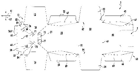
second side panel foldably
connected to the bottom panel, and a corner reinforcement flap foldably
connected to the top panel. A
reinforcing insert comprises a central panel and at least one reinforcing side
flap. The central panel
can be at least partially in face-to-face contact with at least a portion of
the top panel. A container-
restraining structure comprises the corner reinforcement flap positioned to
restrain at least one
container of the plurality of containers that is adjacent the second side
panel.
[0005] In another aspect, the disclosure is generally directed to, in
combination, a carton blank
and an insert blank for forming a carton having container-restraining features
for restraining
movement of containers in the carton. The carton blank comprises a plurality
of panels comprising a
top panel, a first side panel foldably connected to the top panel, a bottom
panel foldably connected to
the first side panel, a second side panel foldably connected to the bottom
panel, and a corner
reinforcement flap foldably connected to the top panel. The insert blank
comprises a central panel
CA 02794869 2012-09-27
WO 2011/150036
PCT/US2011/037872
2
and at least one reinforcing side flap foldably connected to the central
panel. The central panel is for
being positioned at least partially in face-to-face contact with at least a
portion of the top panel. The
container-restraining features comprise the corner reinforcement flap, which
is for being positioned
to restrain at least one container that is adjacent the second side panel in
the carton formed from the
carton blank and the insert blank.
[0006] In
another aspect, the disclosure is generally directed to a method of forming a
carton
comprising obtaining a carton blank comprising a plurality of panels
comprising a top panel, a first
side panel foldably connected to the top panel, a bottom panel foldably
connected to the first side
panel, a second side panel foldably connected to the bottom panel, and a
corner reinforcement flap
foldably connected to the top panel. The method further comprises obtaining an
insert blank
comprising a central panel and at least one reinforcing side flap foldably
connected to the central
panel, and positioning the insert blank relative to the carton blank so that
the central panel overlaps at
least a portion of the top panel. The method further comprises forming an
interior of the carton at
least partially defined by the plurality of panels, and forming a container-
restraining structure
comprising the corner reinforcement flap. The forming the container-
restraining structure comprises
positioning the corner reinforcement flap for restraining at least one
container adjacent the second
side panel in the interior of the carton.
[0007] Those
skilled in the art will appreciate the above stated advantages and other
advantages
and benefits of various additional embodiments reading the following detailed
description of the
embodiments with reference to the below-listed drawing figures.
[0008]
According to common practice, the various features of the drawings discussed
below are
not necessarily drawn to scale. Dimensions of various features and elements in
the drawings may be
expanded or reduced to more clearly illustrate the embodiments of the
disclosure.
BRIEF DESCRIPTION OF THE DRAWINGS
[0009] Fig. 1
is an exterior plan view of a carton blank for forming a carton according to
one
exemplary embodiment of the disclosure.
[0010] Fig. 2
is a plan view of an insert blank for forming a reinforcing insert according
to the
exemplary embodiment of the disclosure.
[0011] Figs. 3-
7 are perspective views of the insert blank of Fig. 2 and the carton blank of
Fig. 1
in various stages of formation of the carton according to the exemplary
embodiment of the disclosure.
CA 02794869 2012-09-27
WO 2011/150036
PCT/US2011/037872
3
[0012] Figs. 8
and 9 are perspective views of the interior of an open-ended sleeve formed
from
the insert blank of Fig. 2 and the carton blank of Fig. 1.
[0013] Fig. 10
is a perspective view of the erected carton according to the exemplary
embodiment
of the disclosure.
[0014]
Corresponding parts are designated by corresponding reference numbers
throughout the
drawings.
DETAILED DESCRIPTION OF THE EXEMPLARY EMBODIMENTS
[0015] The
present disclosure generally relates to cartons that contain articles such as
containers,
bottles, cans, etc. The articles can be used for packaging food and beverage
products, for example.
The articles can be made from materials suitable in composition for packaging
the particular food or
beverage item, and the materials include, but are not limited to, aluminum
and/or other metals; glass;
plastics such as PET, LDPE, LLDPE, HDPE, PP, PS, PVC, EVOH, and Nylon; and the
like, or any
combination thereof.
[0016] Cartons
according to the present disclosure can accommodate articles of any shape. For
the purpose of illustration and not for the purpose of limiting the scope of
the disclosure, the
following detailed description describes beverage containers (e.g., glass
beverage bottles) as disposed
within the carton embodiments. In this specification, the terms "lower,"
"bottom," "upper" and "top"
indicate orientations determined in relation to fully erected and upright
cartons.
[0017] Fig. 1
is a plan view of the exterior side 1 of a carton blank, generally indicated
at 3, used
to form a carton 5 (Fig. 10) according to one exemplary embodiment of the
disclosure. The carton 5
can be used to house a plurality of articles, such as containers C (Fig. 9).
In the illustrated
embodiment, the carton 5 is sized to house twelve containers C in a single
layer in a 3x4 arrangement,
though only nine of the twelve containers are shown in the carton in Fig. 9.
It is understood that the
carton 5 may be sized and shaped to hold containers of a different or same
quantity in more than one
layer and/or in different row/column arrangements (e.g., 1x6, 3x6, 2x6x2, 4x5,
3x5, 2x9, 2x6, 3x3,
etc.). In one embodiment, the carton 5 has a dispenser 7 for accessing the
containers C in the carton.
In the illustrated embodiment, the carton 5 includes a handle, generally
indicated at 11, for grasping
and carrying the carton. As will be discussed below in more detail, the carton
5 includes an insert
205 formed from an insert blank 203 for reinforcing the carton. In addition,
features of the insert
blank 203 and the carton blank 3 form a container-restraining structure 13 for
restraining the
movement of the containers C.
CA 02794869 2012-09-27
WO 2011/150036
PCT/US2011/037872
4
[0018] As shown
in Fig. 1, the carton blank 3 has a longitudinal axis Li and a lateral axis
L2.
The carton blank 3 comprises a top panel 10 foldably connected to a first side
panel 20 at a first
lateral fold line 21. A bottom panel 30 is foldably connected to the first
side panel 20 at a second
lateral fold line 31. A second side panel 40 is foldably connected to the
bottom panel 30 at a third
lateral fold line 41.
[0019] In the
illustrated embodiment, the carton blank 3 includes a corner reinforcement
flap 50
foldably connected to the top panel 10 at a fourth lateral fold line 52. The
corner reinforcement flap
50 comprises four panels or portions 54, 56, 58, 60 that are independently
positionable at respective
fold lines 52, 57, 59, 65. In the illustrated embodiment, the first portion 54
of the corner
reinforcement flap 50 has corner end flaps 82, 84. The corner reinforcement
flap 50 could be
otherwise shaped, arranged, and/or configured without departing from the
disclosure. In alternative
embodiments, the carton blank 3 can be arranged so that the top panel 10 is
foldably connected to
both the first and second side panels 20, 40, or the blank 3 can have other
alternative panel
arrangements.
[0020] The top
panel 10 is foldably connected to a first top end flap 12 and a second top end
flap
14. The first side panel 20 is foldably connected to a first side flap 22 and
a second side flap 24. The
bottom panel 30 is foldably connected to a first bottom end flap 32 and a
second bottom end flap 34.
The second side panel 40 is foldably connected to a first side flap 42 and a
second side flap 44.
When the carton 5 is erected, the top and bottom end flaps 12 and 32, the side
end flaps 22 and 42,
and the corner end flap 82 close a first end 51 of the carton, and the top and
bottom end flaps 14 and
34, the side end flaps 24 and 44, and the corner end flap 84 close a second
end 53 of the carton. In
accordance with an alternative embodiment of the present disclosure, different
flap arrangements can
be used for at least partially closing the ends 51, 53 of the carton 5.
[0021] The top
and bottom end flaps 12 and 32 and side end flaps 22 and 42 extend along a
first
marginal area of the carton blank 3, and are foldably connected at a first
longitudinal fold line 62 that
extends along the length of the blank. The top and bottom end flaps 14 and 34
and side end flaps 24
and 44 extend at least partially along a second marginal area of the carton
blank 3, and are foldably
connected at a second longitudinal fold line 64 that also extends at least
partially along the length of
the blank. The longitudinal fold lines 62, 64 may be, for example,
substantially straight, or offset at
one or more locations to account for blank thickness or for other factors.
[0022] In the
illustrated embodiment, the carton blank 3 includes features to form the
carton 5
having tapered ends 51, 53. That is, the blank includes diamond corner panels
67, 69 that connect
respective side end flaps 22, 42, 24, 44 to a respective one of the first side
panel 20 and the second
CA 02794869 2012-09-27
WO 2011/150036
PCT/US2011/037872
side panel 40. The diamond corner panels 67, 69 are configured to allow the
top end flaps 12, 14 and
the portions of the side end flaps 22, 42, 24, 44 in contact with the
respective top flaps 12, 14 (e.g.,
the upper portions of the side end flaps) at the respective ends 51, 53 to
taper inwardly to the top
panel 10. The bottom panel 30 is longer in the L2 direction than the top panel
10. Accordingly, the
containers C having a wide bottom B and narrow top T can be tightly held in
the carton. Particularly,
the bottoms B of the containers C adjacent the side panels 20, 40 and the ends
51, 53 are restrained
by the respective side panels and ends, and the tops T adjacent the ends 51,
53 are restrained by the
respective tapered upper portions 81, 83 of the respective ends 51, 53 (Fig.
10). In alternative
embodiments, the carton 5 could be otherwise shaped, arranged, and/or
configured. For example, the
ends 51, 53 can taper inwardly from a respective edge of the bottom panel 30
to a respective edge of
the top panel 10, any suitable portion of the ends 51, 53 can taper inwardly,
or the ends can extend
generally vertically.
[0023] As shown
in Fig. 1, the features that form the handle 11 of the carton 5 include a
first
elongate handle flap 71 foldably connected to the top panel 10 at a lateral
fold line 73, and a second
elongate handle flap 75 foldably connected to the top panel at a lateral fold
line 77. The handle 11
may be otherwise shaped and located in the carton 5 without departing from the
scope of this
disclosure.
[0024] Fig. 2
illustrates the insert blank 203 used to form the reinforcing insert 205 (Fig.
8) for
use in the carton 5. In the illustrated embodiment, the insert blank 203
includes a central panel 206,
two reinforcing end flaps 212, 214 respectively foldably connected to the
central panel 206 at
respective fold lines 215, 217 at opposite ends of the central panel 206. The
central panel 206 has
two handle openings 216, 218 with a tab 220 extending adjacent the handle
opening 218. The insert
blank 203 has a first reinforcing side flap 219 and a second reinforcing side
flap 221 foldably
connected to the central panel 206 at respective fold lines 223, 225 at
opposite sides of the central
panel 206. The second reinforcing side flap 221 is further defined by two cuts
226 at respective ends
of the fold line 225.
[0025] In the
illustrated embodiment, the second reinforcing side flap 221 has a handle
opening
229 with a first handle flap 231 foldably connected to the second reinforcing
side flap 221 along a
fold line 232. A second handle flap 233 is foldably connected to the second
reinforcing side flap 221
at a fold line 234. The handle openings 216, 218 in the central panel 206 and
the handle opening 229
and the handle flaps 231, 233 in the second reinforcing side flap 221
cooperate with the handle flaps
71, 75 in the top panel 10 to form the handle 11 (Fig. 4). The second
reinforcing side flap 221 can
further include two inner reinforcing end flaps 236, 238 foldably connected to
the second reinforcing
side flap 221 along the respective fold lines 215, 217. In the illustrated
embodiment, the first
CA 02794869 2012-09-27
WO 2011/150036
PCT/US2011/037872
6
reinforcing side flap 219 comprises three panels or portions, including a
proximal portion 237, an
intermediate portion 239, and a distal portion 241, that are independently
positionable at respective
fold lines 243, 245. In alternative embodiments, the reinforcing insert 205
could be otherwise
shaped, arranged, and/or configured.
[0026] As shown
in Figs. 3-9, in one exemplary embodiment, the carton 5 can be assembled by
adhering the end flap portion 60 of the corner reinforcement flap 50 to the
top panel 10 with the
application of glue 262 (Fig. 3). The corner reinforcement flap 50 is folded
about fold line 57 in the
direction of arrow Al (Fig. 3) so that the end flap portion 60 is in face-to-
face contact with the top
panel 10 (Fig. 5). As shown in Figs. 4, the insert blank 203 is adhered to the
top panel 10 of the
carton blank 3 on an interior surface 4 of the carton blank. Glue can be
applied in strips 275, 277,
279, 281 (Fig. 2) to the interior surface of the central panel 206 prior to
placing the insert blank 203
in face-to-face contact with the top panel 10. The insert blank 203 is
positioned on the top panel 10
so that the fold line 225 is adjacent the free edge 263 (Fig. 5) of the end
flap portion 60 of the corner
reinforcement flap 50 and the handle openings 216, 218 are generally aligned
with the respective
handle flaps 71, 75 in the top panel 10. The insert blank 206 can be
alternatively secured to the top
panel 10 without departing from the disclosure.
[0027] In the
illustrated embodiment, the insert blank 203 is attached to the top panel 10
of the
carton blank in a manner that keeps the reinforcing side flaps 219, 221 free
from attachment to the
carton blank 3. As shown in Fig. 4, the second reinforcing side flap 221 is
folded about fold line 225
in the direction of arrow A2 so the second reinforcing side flap 221 is in
face-to-face contact with the
central panel 206. The second reinforcing side flap 221 can be adhered to the
central panel 206 with
the handle opening 229 and the handle flap 231 are generally aligned with the
handle opening 216 in
the center panel 206 and the handle flap 71 in the top panel 10. The handle
flap 233 in the second
reinforcing side flap 221 is generally aligned with the handle opening 218 in
the central panel 206
and the handle flap 73 in the top panel 10. Accordingly, the central panel 206
and the second
reinforcing side flap 221 reinforce the handle 11 of the carton 5.
[0028] As shown
in Fig. 5, the first reinforcing side flap 219 can be folded about fold line
243 in
the direction of arrow A3 to position the reinforcing side flap 219 as shown
in Fig. 6 so that the
intermediate portion 239 and the distal portion 241 of the first reinforcing
side flap 219 are at least
partially in face-to-face contact with the central panel 206. In one
embodiment, a portion of the distal
portion 241 of the first reinforcing side flap 219 can be temporarily tucked
under the tab 220 in the
central panel 206 (Fig. 6). As shown in Fig. 7, glue can be applied to the
interior surface of the distal
portion 241 of the reinforcing side flap 219 in a strip 268. The top panel 10,
with the insert 205
partially assembled, can be folded about fold line 21 in the direction of
arrow A4 so that the distal
CA 02794869 2012-09-27
WO 2011/150036
PCT/US2011/037872
7
portion 241 of the first reinforcing side flap 219 is attached to the side
panel 20 by the glue strip 268.
Also, the second reinforcing side flap 221 and the corner reinforcement flap
50 are brought into face-
to-face contact with the side panel 20, when the top panel is downwardly
folded from the position of
Fig. 7.
[0029] In the
illustrated embodiment, the second side panel 40 and the bottom panel 30 of
the
carton blank 3 are folded along fold line 31 so that the top portion of the
second side panel 40 can be
glued in face-to-face contact to the exterior surface of the first portion 54
of the corner reinforcement
flap 50. As shown in Figs. 8 and 9, the carton blank 3 and the reinforcing
insert 205 are further
positioned and formed into a generally open-ended sleeve 305. The carton blank
3 can be folded
about fold lines 21, 31, 41, 52 to position the side panels 20, 40, the top
panel 10, and the bottom
panel 30 to form the sleeve 305 with an interior 306. The corner reinforcement
flap 50 is configured
to stabilize the row of containers C that is adjacent to the second side panel
40. As shown in Figs. 8
and 9, the second portion 56 and the third portion 58 of the corner
reinforcement flap 50 remain
unattached to the blank 3 (e.g., the top panel 10 and side panel 40).
Accordingly, the second portion
56 can extend generally inwardly from the second side panel 40, and the third
portion 58 can extend
generally upwardly from the second portion 56 to the fourth portion 60, which
is in face-to-face
contact with the top panel 10. As shown in Fig. 9, at least the sides of the
top portions T of the
containers C can abut at least the third portion 58 of the corner
reinforcement flap 50 to stabilize the
containers in the carton 5. The corner reinforcement flap 50 could be
otherwise shaped, arranged,
configured, and/or omitted without departing from the disclosure.
[0030] In the
illustrated embodiment, the first reinforcing side flap 219 disengages from
the tab
220 as the sleeve 305 is erected, and the first reinforcing side flap 219
extends generally downwardly
from the central panel 206 of the insert 205 in a manner that reinforces the
row of containers C
adjacent to the first side panel 20. The distal portion 241 of the first
reinforcing side flap 219 is
adhesively secured in face-to-face contact to the first side panel 20 as
described above. The
intermediate portion 239 and the proximal portion 237 are free from attachment
to either the side
panel 20 or top panel 10 of the carton blank 3 so that at least the sides of
the top portions T of the
containers C that are adjacent the first side panel 20 can contact the
intermediate portion 239 and/or
the proximal portion 237. The intermediate portion 239 can extend upwardly
from the distal portion
241 and be positioned at an oblique angle relative to the side panel 20 and
the top panel 10, and the
proximal portion 237 can extend upwardly from the intermediate portion 239 and
be positioned at an
oblique angle relative to the top panel 10 and the side panel 20. The proximal
portion 237 and the
intermediate portion 239 can be positioned at the same oblique angle or
different oblique angles. The
CA 02794869 2012-09-27
WO 2011/150036
PCT/US2011/037872
8
reinforcing features of the insert 205 could be otherwise shaped, arranged,
configured, and/or omitted
without departing from the disclosure.
[0031] As
shown in Figs. 8 and 10, the first end 51 of the carton 5 can be closed by
respectively
overlapping and adhering the side end flaps 22, 42, the top and bottom end
flaps 12, 32, and the
corner end flap 82. As the top end flap 12 is folded downwardly, the top end
flap 12 contacts the
reinforcing end flap 212, which, in turn, contacts the inner reinforcing end
flap 236. Accordingly, the
top end flap 12 folds the reinforcing end flap 212 and the inner reinforcing
end flap 236 downwardly
as the first end 51 is closed. At least the top end flap 12, the reinforcing
end flap 212, the inner
reinforcing end flap 236, and the upper portions of the side end flaps 22, 42
are angled inwardly in
the closed first end 51.
[0032] In the
illustrated embodiment, the second end 53 has similar features as the first
end 51
and can be closed in substantially the same manner as the first end 51. The
closed second end 53 is
shown in Fig. 10. The containers C can be loaded into the carton 5 after
closing one of the ends 51,
53, or before closing either end. At least the top end flap 14, the
reinforcing end flap 214, the inner
reinforcing end flap 238, and the upper portions of the side end flaps 24, 44
are angled inwardly in
the closed second end 53. Alternatively, the second end 53 can be otherwise
configured or closed in
a different manner than the first end 51 without departing from the scope of
the disclosure.
Additionally, alternative assembling, loading, and closing steps may be used
without departing from
the scope of the disclosure.
[0033] In the
illustrated embodiment, the top portions T of the containers C that are
adjacent the
first end 51 and the second end 53 can abut the respective tapered upper
portions 81, 83 of the
respective closed ends 51, 53 to help restrain the containers. Accordingly,
the containers adjacent the
first closed end 51 can contact at least the top end flap 12, the reinforcing
end flap 212, the inner
reinforcing end flap 236, and the upper portions of the side end flaps 22, 42,
and the containers C
adjacent the second closed end 53 an contact at least the top end flap 14, the
reinforcing end flap 214,
the inner reinforcing end flap 238, and the upper portions of the side end
flaps 24, 44.
[0034] The
first reinforcing side flap 219 of the insert 205 and the corner reinforcing
flap 50 form
the container-restraining structure 13, as shown in Figs. 8 and 9.
Accordingly, the first reinforcing
side flap 219 and the corner reinforcement flap 50 provide restraint to the
tops T for the containers C
that are adjacent the side panels 20, 40 of the carton 5. In this manner, the
container-restraining
structure 13 cooperates with the tapered portions of the ends 51, 53 to help
prevent excessive
movement of the containers C in the carton 5.
CA 02794869 2012-09-27
WO 2011/150036
PCT/US2011/037872
9
[0035] In the
illustrated embodiment, the reinforcing side flap 221 overlays the features of
the
handle 11 to reinforce the handle and increase the strength of the carton 5.
The reinforcing handle
features of the insert 205 could be otherwise shaped, arranged, configured,
and/or omitted without
departing from the disclosure.
[0036] The
blanks according to the present disclosure can be, for example, formed from
coated
paperboard and similar materials. For example, the interior and/or exterior
sides of the blanks can be
coated with a clay coating. The clay coating may then be printed over with
product, advertising,
price coding, and other information or images. The blanks may then be coated
with a varnish to
protect any information printed on the blank. The blanks may also be coated
with, for example, a
moisture barrier layer, on either or both sides of the blank. In accordance
with the above-described
embodiments, the blanks may be constructed of paperboard of a caliper such
that it is heavier and
more rigid than ordinary paper. The blanks can also be constructed of other
materials, such as
cardboard, hard paper, or any other material having properties suitable for
enabling the carton to
function at least generally as described herein. The blanks can also be
laminated or coated with one
or more sheet-like materials at selected panels or panel sections.
[0037] In
accordance with the above-described embodiments of the present disclosure, a
fold line
can be any substantially linear, although not necessarily straight, form of
weakening that facilitates
folding therealong. More specifically, but not for the purpose of narrowing
the scope of the present
disclosure, fold lines include: a score line, such as lines formed with a
blunt scoring knife, or the
like, which creates a crushed portion in the material along the desired line
of weakness; a cut that
extends partially into a material along the desired line of weakness, and/or a
series of cuts that extend
partially into and/or completely through the material along the desired line
of weakness; and various
combinations of these features.
[0038] As an
example, a tear line can include: a slit that extends partially into the
material along
the desired line of weakness, and/or a series of spaced apart slits that
extend partially into and/or
completely through the material along the desired line of weakness, or various
combinations of these
features. As a more specific example, one type tear line is in the form of a
series of spaced apart slits
that extend completely through the material, with adjacent slits being spaced
apart slightly so that a
nick (e.g., a small somewhat bridging-like piece of the material) is defined
between the adjacent slits
for typically temporarily connecting the material across the tear line. The
nicks are broken during
tearing along the tear line. The nicks typically are a relatively small
percentage of the tear line, and
alternatively the nicks can be omitted from or torn in a tear line such that
the tear line is a continuous
cut line. That is, it is within the scope of the present disclosure for each
of the tear lines to be
CA 02794869 2012-09-27
WO 2011/150036
PCT/US2011/037872
replaced with a continuous slit, or the like. For example, a cut line can be a
continuous slit or could
be wider than a slit without departing from the present disclosure.
[0039] The
above embodiments may be described as having one or more panels adhered
together
by glue during erection of the carton embodiments. The term "glue" is intended
to encompass all
manner of adhesives commonly used to secure carton panels in place.
[0040] The
foregoing description of the disclosure illustrates and describes various
embodiments.
As various changes could be made in the above construction without departing
from the scope of the
disclosure, it is intended that all matter contained in the above description
or shown in the
accompanying drawings shall be interpreted as illustrative and not in a
limiting sense. Furthermore,
the scope of the present disclosure covers various modifications,
combinations, alterations, etc., of
the above-described embodiments that are within the scope of the claims.
Additionally, the
disclosure shows and describes only selected embodiments of the disclosure,
but the disclosure is
capable of use in various other combinations, modifications, and environments
and is capable of
changes or modifications within the scope of the inventive concept as
expressed herein,
commensurate with the above teachings, and/or within the skill or knowledge of
the relevant art.
Furthermore, certain features and characteristics of each embodiment may be
selectively interchanged
and applied to other illustrated and non-illustrated embodiments of the
disclosure.