Note: Descriptions are shown in the official language in which they were submitted.
CA 02795472 2012-10-04
WO 2011/126486 PCT/US2010/030375
METHOD OF MODELING THE COLORING PROCESS IN MOVING WEB
MANUFACTURING
FIELD
[0001] The present specification relates to the manufacture of rolls, and more
particularly to a method and apparatus for modeling the coloring process in
moving
paper web manufacturing for optimum control of sheet color with colorants and
optical
brightening agents.
BACKGROUND
[0002] Tinting and/or coloring paper by the use of colorants, such as dyes and
optical
brightening agents (OBAs) has been common for many years in the operation of
paper
making machines. The actual sheet or web color is determined by measuring the
reflectance spectrum of the web sheet as it travels through the production
process. For
example, measurement may be performed by an online spectrophotometer that
measures the reflectance spectrum of the sheet. Dye additions can be made at
different
stages of the paper making process to achieve a desired color shade.
[0003] The spectrophotometer is typically mounted to a scanning device for
continuously measuring sheet color reflectance spectrum from a standard light
source
that is directed at one side of the sheet, with a backing background on the
opposite side
of the sheet chosen for reducing opacity effects. The measured sheet
reflectance
spectrum range is typically from 360 to 720 nm in wavelength, covering the
range of
visible light wavelengths plus a portion of the ultra-violet spectrum. By
using a set of
standard non-linear equations, the sheet reflectance spectrum can be used to
calculate
sheet color in terms of various defined coordinate systems, for example CIE
L*, a*, b*
values, where L` represents a lightness axis ranging from 0 for black and 100
for white,
a` represents a red-green axis where a positive number is indicative of
redness while a
negative number is indicative of greenness, and b* represents a blue-yellow
axis where
a positive number is indicative of yellowness while a negative number is
indicative of
more blueness.
[0004] Control of the sheet color using a set of dyes requires knowledge of
the
response model for each dye, which is typically represented by sheet color
reflectance
spectrum value change given a normalized dye flow ratio change, for example,
pound-
per-ton of fiber stock used to make the paper. With knowledge of the sheet
target value
(L,, at, bt) and measured sheet value (Lm, am, bm) and the response model for
each dye, a
CA 02795472 2012-10-04
WO 2011/126486 PCT/US2010/030375
2
control algorithm can be used to calculate the dye flow ratio change for
minimizing sheet
color error from the target value, normally represented by AE, as follows: AE
= sqrt[(Lt
Lm)2 '(a( -- am)2+(bt - bm)2].
[0005] The dye response model (Le. reflectance spectrum value change per unit
dye
ratio change) is normally obtained through the use of a "bump" test. For
example, under
normal operating conditions with manual color control and a stable production
process,
the measured sheet reflectance spectrum value change is calculated before and
after a
dye ratio change and the normalized spectrum difference is used for the dye
response
model. This model has been found to be valid for paper production of similar
sheet color
as produced during the "bump' test.
[0006] Color changes made during the production of paper often result in 'off-
spec'
sheet material being produced, both during and after such color changes. This
`off-spec'
web, referred to as color broke, is typically recycled back to the early
stages of
production. Accordingly, one of the goals in sheet color control is to develop
an accurate
dye response model that quickly minimizes the error between the measured sheet
color
and the target color, thereby reducing the occurrence of sheets that are off-
specification
during and following a grade change or at start-up or as a result of
disturbances that
may occur during steady-state, and thereby also reducing costs.
[0007] It is also known in the prior art to model the steady state behaviour
of the coloring
process by determining a steady state gain from the dye flow to the measured
color at
different concentrations, or by spectral response models obtained by dye
response tests.
One example of dye response model gain adaptation is described in US Patent
No.
6,052,194 (Nuyan), the contents of which are incorporated herein by reference.
In either
dye response model gain adaptation or spectral response modelling, the
resulting model
is grade-dependent. This grade dependency is especially severe in the case of
dye
response model gain adaptation because of the highly non-linear relationship
of
measured color to the measured sheet spectrum.
[0008] The dye response model, described above, can be decomposed into a
normalized response shape over the spectrum range (360 to 720 nm, with unit
gain),
and associated with a response gain (i.e. a scalar) for gain adaptation by
creating a non-
linear table of actual dye flow ratio used and the associated response gain,
while
keeping the response shape constant. The non-linear table may be calculated
using a
series of bump tests during the production process using different dye ratios.
When
using this type of gain adaptation, a base flow must be added to the actual
dye flow in
CA 02795472 2012-10-04
WO 2011/126486 PCT/US2010/030375
3
order to represent an "equivalent" amount of dye in the broke stock.
[0009] The model gain and base flow relation is highly non-linear. For
instance, the gain
difference could be as high as several thousand folds when producing light
shade color
(normally low dosage of dye) and dark shade color (normally high dosage) of
paper. To
get an accurate relation of gain-base flow curve, many "bump" tests were
needed.
[0010] There are at least two issues that have limited the use of the dye
response
model gain adaptation set forth above. First, it has been observed that when
producing a
deep shade color paper, the actual dye response gain is significantly smaller
than when
producing light shade color paper for the same dye using a similar dye ratio.
Second,
when a large amount of broke is used as furnish, there is no accurate way to
estimate
the corresponding base flow (added offset of a dye flow) of the dye. It has
been
reported that the amount of broke can be as high as 80% in extreme cases.
[0011] Furthermore, it has been discovered that the dye response shape over
the
spectrum can depend on the measured sheet color, especially when the sheet
color
shade is dark. The difference can in some circumstances be so large that the
resulting
control action is in the opposite direction to the predicted response based on
dye flows.
SUMMARY
[0012] A method is set forth in greater detail below for modeling the coloring
process in
moving web manufacturing for optimum control with dyes and optical brightening
agents
(OBA's). The method does not require the traditional on-line step response
tests (bump
tests) and relies only on the measured reflectance spectrum of the moving web
and on
predetermined spectral reflectance data of a set of sample sheets (normally
provided by
dye suppliers and stored in the color control system).
[0013] According to one aspect of this specification, there is provided a
color modeling
process for use in manufacturing a colored material, comprising a-priori
measuring of the
reflectance spectra of sample materials covering a range of production colors
and
determining therefrom a model; and on-line measuring of the reflectance
spectrum of
said colored material and applying said model thereto for at least one of
predicting color
trajectory or generating control actions to regulate the flow of at least one
of a colorant or
optical brightening agent.
[0014] According to another aspect, there is provided a color control process
for use in
color paper web manufacturing, comprising a-priori measuring of the
reflectance spectra
of sample sheets covering a range of known concentrations of at least one of a
colorant
CA 02795472 2012-10-04
WO 2011/126486 PCT/US2010/030375
4
or optical brightening agent and determining therefrom a model; and on-line
measuring of the reflectance spectrum of said color paper web and applying
said model
thereto for generating control actions to regulate the flow of said at least
one of a
colorant or optical brightening agent applied to the color web for achieving a
target color
or brightness.
[0015] According to a further aspect, there is provided an apparatus for
controlling the
color of a web of paper, comprising a spectrophotometer for scanning said web
of paper;
a plurality of regulators; and a color controller connected to said
spectrophotometer and
regulators for a-priori measuring of the reflectance spectra of sample sheets
covering a
range of known concentrations of at least one of a colorant or optical
brightening agent
and determining therefrom a model, and on-line measuring of the reflectance
spectrum
of said color paper web and applying said model thereto for generating and
transmitting
control actions to said a plurality of regulators for regulating the flow of
said at least one
of a colorant or optical brightening agent applied to the color web for
achieving a target
color or brightness.
[0016] For each colorant, a set of color samples is provided with different
known dye
ratios to the pulp, as well as a "white" sample with no dye added. The sheet
reflectance
spectrum is measured (off-line) for each color sample and the white sample.
For each
dye, a 'dye absorption wavelength' is identified from the measured reflectance
spectrum
samples at which the reflectance spectrum value is minimum. During the
production
process (i.e. on-line) the measured sheet color reflectance spectrum value and
the dye
absorption wavelength are used for colorant model response shape and gain
adaptation.
The adaptation table is generated from the samples, as follows: for given
samples "A"
and "B", the dye response is (spectrum of sample A -- spectrum of sample
B)/(concentration of sample A - concentration of sample B). The normalized
result
spectrum (normalized on a scale of -1 to 0) comprises the dye response shape
and the
associated multiplying factor comprises the dye response gain. The adaptation
point is
based on the average spectrum value of sample A and sample B at the dye
absorption
wavelength. When the measured sheet reflectance spectrum value at the
absorption
wavelength falls between two adaptation points, a weighted interpolation is
used to
generate both the color model response shape and the response gain.
[0017] The method set forth above can also be applied when "tinting" the
moving web
with colorants, for example by adding a blue colorant to a red sheet or adding
a small
amount of yellow colorant to a deep shade of blue sheet. Additional method
steps are
CA 02795472 2012-10-04
WO 2011/126486 PCT/US2010/030375
set forth to reduce the set of response models generated as described above
into a
fundamental model set from which the applicable response is generated
adaptively
using the measured color spectrum.
[0018] According to another aspect of the specification, the construction of
adaptive
response gains is set forth where the adaptation is based on the previous
control actions
and their measured effects in the reflectance spectrum of the sheet, for fast
color
changes required when the manufacturer makes color grade changes. For example,
when full control results in the measured sheet color changing toward the
target by only
a fraction of the full distance (SE) in the color (L, a, b) space as compared
with the
predicted change, the model gain can be reduced for more aggressive color
change.
This can account for dye retention differences at the initial stage of
producing a dark
paper grade (i.e. a sheet with small L value). Such aggressive adaptation is
not typically
necessary when the production stabilizes near its color target.
BRIEF DESCRIPTION OF THE DRAWINGS
[0019] Exemplary embodiments will be better understood with reference to the
following
FIGS in which like numerals denote like parts and in which:
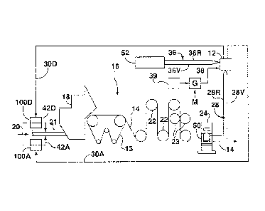
[0020] FIG. 1 is a schematic representation of a machine for making colored
paper that
incorporates a controller for modeling the coloring process according to an
exemplary
embodiment;
[0021] FIG. 2 is a flowchart showing a method for effecting the coloring
process using
the controller of FIG. 1, according to an exemplary embodiment
[0022] FIGS 3A- 3C are schematic representations of an exemplary set of dye
response gains and response spectra for a typical red dye sample sheet,
wherein FIG.
3A shows reflectance spectra of a sample sheet using different red dye
concentration
and of a white base sheet, FIG. 3B shows reflectance spectra difference
normalized with
respect to concentration difference from the white base sheet (i.e. spectrum
difference
per unit change in colorant), and FIG. 3C shows reflectance spectra difference
normalized using two different samples of similar color shade (for examples:
using 200
lb sample and 400 lb. sample, or using 8 .lb sample or 15 lb. sample);
[0023] FIG. 4 is a schematic representation of functional components of the
controller
depicted in FIG. 1 for effecting the coloring process set forth in FIGS. 2 and
3.
DETAILED DESCRIPTION
CA 02795472 2012-10-04
WO 2011/126486 PCT/US2010/030375
6
[0024] Turning to FIG. 1 of the drawings, a color controller 12 controls the
color of a web
of paper 14 produced by a paper machine indicated by the reference numeral 16.
Paper
machine 16 includes a headbox 18 that discharges a wet paper web 14 from a
slurry of
pulp 20 which flows through pipe 21 to headbox 18. Web 14 is initially
supported by a
porous belt 13 and acquires strength and form as it passes along rollers 22 to
a pair of
opposed press rollers 23 which may be used for surface sizing or for pigmented
surface
coatings. Web 14 eventually passes through a frame 24 along which a
spectrophotometer 50 scans the width of paper web 14.
[0025] Spectrophotometer 50 uses a light source to light the web 14. Light
reflected by
the web passes to a grating that splits the light into the full spectrum of
colors. The
spectrum of light impinges upon a diode array that measures the amount of
light at each
wavelength. The spectral data is sent to controller 12 in the form of measured
reflectance signals (indicated generally by the reference numeral 28) taken at
a number
of wavelength bands, typically seventy two, spanning the visible spectrum
(e.g. 360 to
720 nm wavelength in 5 nm intervals). This spectral data may, for example, be
expressed as X, Y, Z tristimulus colorimeter values. However, because X, Y and
Z values
are not easily understood in terms of object color, other color scales have
been
developed to simplify understanding, improve communication of color
differences and
which are more linear throughout color space. As discussed above, one example
of such
a color scale is the CIE LW, a*, b' color space, which is mathematically
derived from the X,
Y, Z values, and where L` represents a lightness axis, a" represents a red-
green axis and
b' represents a blue-yellow axis, according to opponent-colors theory.
[0026] The measured spectral data is multiplied together with target
reflectance values
indicated generally by the reference numeral 36 and stored in memory 52,
representing
dye response gain and dye response spectrum shape for each sample. Non-linear
equations representing color gain in the measured color spectrum are used to
calculate
the gradients and direction directives in the color control optimization, as
discussed in
greater detail below. Any number of dyes can be used for the color control
(but typically
the number of dyes used is I to 4).
[0027] Controller 12 generates dye flow control signals 30D and additive flow
control
signals 30A. Independently controlled indexers 39 provide signals which are
coupled
through gates 38 to controller 12 to change the flow of additives applied to
the web 14. A
signal M enables gates 38 at certain times for metering the flow of additives.
[0028] In response to dye flow control signals 30D from controller 12, dye
flow
CA 02795472 2012-10-04
WO 2011/126486 PCT/US2010/030375
7
regulators I OOD dispense dyes 42D to control the color of web 14. In response
to
additive flow control signals 30A, additive regulator 100A dispenses
controlled volumes
of additives 42A that affect other qualities of paper web 14.
[0029] As described in greater detail below, two new aspects of color control
are
provided by controller 12: dye response gain adaptation using measured sheet
color
spectrum value at the dye absorption wavelength; and dye response shape
adaptation
using measured color spectrum of the production sheet.
[0030] Having regard to the former, the adaptation of colorant (dye) response
gain uses
the measured sheet color spectrum value at the value of maximum light
absorbance of
the dye. This wavelength is referred to herein as the dye absorption
wavelength, which
can be identified from sample sheets as the most negative point in the
reflectance
spectrum difference between a colorant sample sheet and a white base sheet.
This
wavelength is usually the same for all samples using the same dye with
different dye
concentrations.
[0031] Having regard to the latter, it has been discovered that when a dye
concentration
changes, its influence is linear in ratio of light absorption to scattering
rather than in light
reflectance. More particularly, the relation is highly non-linear for deep
shade color
sheets but has close-to-linear relation for light shade colour sheet (i.e. the
relation
between the color sensed by spectrophotometer 50 as represented by light
reflectance
to light absorption is highly non-linear when the sheet color is dark). The
adaptation of
dye response spectrum therefore uses the measured sheet color reflectance
spectrum
and the sample sheet color spectrum with a corresponding response shape
calculated
using a formula to adapt the current sheet condition dye response shape using
the dye
response from the sample sheet on the assumption of a constant ratio of
absorption
change to dye concentration change.
[0032] Turning now to F1GS. 2 - 4, additional features of operation of the
controller 12
are set forth. First, a-priori off-line measurement is conducted (step 200 in
FIG. 2) of the
reflectance spectra of pre-specified colour sample sheets (e.g. 12 handsheets)
per
colorant and OBA's covering a range of concentrations of interest in the
manufacturing of
a particular color or shade as well as combinations of colorant dosages used
for tinting.
A measurement of the reflectance spectrum is also taken for a white sample
sheet
having no colorant. FIG. 3A shows the measured color spectra of the white
sample sheet
(top) and red samples having different concentrations of dye (from 2 oz/ton to
400
lb/ton), where wavelength is represented by the x-axis and reflectance is
represented by
CA 02795472 2012-10-04
WO 2011/126486 PCT/US2010/030375
8
the y-axis (with 0 representing 100% absorption and I representing 100%
reflectance).
Measurement values L*, a* and b* for the sample sheets are set forth in Table
1, as
follows:
Table 1: Samples of a typical red dye (with different dye concentrations)
2 oz oz 12 oz 2 lb 18 lb 15 lb 4 lb 8 lb 196 lb 1150 lb 00 lb 14400 lb
L* 191.6 90.8 89.0 86.2 178.1 173.5 68.7 163.0 57.7 54.9 53.1 149.4
* 10.2 1.3 14.1 8.6 0.1 26.1 34.0 1441.8 148.0 151.8 53.3 55.4
b* 0.8 0.8 10.6 0.8 12.8 14.8 8.8 113.6 119.0 1223.3 5.7 30.6
[0033] These measurements are then used to calculate (step 205) a
characteristic dye
absorption wavelength (i.e. the most negative point in the reflectance spectra
difference
between a colorant sample sheet and the white sample sheet). More
particularly, FIG. 3B
shows the calculated spectrum difference between each of the samples in FIG.
3A to the
white (base) sheet, along with the averaged and normalized spectrum (where -1
on the
y-axis indicates maximum absorption). The characteristic dye absorption
wavelength for
the illustrated example is approximately 560 nm.
[0034] Next, at step 210 a set of colorant and OBA responses is calculated for
various
dye concentrations. Specifically, the difference between the sample sheet
reflectance of
each pair of sample sheets (e.g. one such pair being the 8 lb sample and the
24 lb
sample from FIG. 3B) is used to calculate a normalized reflectance spectrum
difference
per unit change in colorant or OBA response (e.g. the response for 16 lb/ton
concentration is indicative of the change in dye dosage from 8 lb to 24 lb).
This
subtraction is performed for each pair of responses in FIG. 36 (normalized to
one pound)
and the difference is then divided by the difference of their corresponding
dosages or
concentrations. The resulting response is then further divided by the minimum
value of
the response (i.e. the process gain) to generate the normalized response
depicted in
FIG. 3C (i.e. normalized with respect to dosages/concentrations and a minimum
value of
-1).
[0035] Then, at step 215, dye response gains are determined for different
reflectance
spectrum values at the characteristic absorption wavelength (i.e. adaptation
point) for
each colorant or OBA. For example, at a concentration of 16 lb/ton, the
normalized dye
response is as shown in FIG. 3A (a spectrum value of 0.33794 at the 560 nm
characteristic dye absorption wavelength) and the response gain is 0.013191.
The
calculated gain adaptation for the red dye of FIGS 3A- 3C is as set forth in
Table 2, and
CA 02795472 2012-10-04
WO 2011/126486 PCT/US2010/030375
9
is stored in memory 52 (FIG. 1):
Reflectance Gain Shade
at 560nm
0.80447 0.24363 Light
0.79206 0,17105 Light
0,74856 0.1466 Light
0.69301 0.090685 Light
0.56506 0,039731 Light
0.4766 0.022157 Light
0.33794 0.013191 Medium
0.25434 0.0075536 Medium
0.18584 0.0024361 Dark
0.13564 0.0015402 Dark
0.12938 0.0011413 Dark
0.092643 0.00057065 Dark
[00361 In order to minimize the number of normalized response shapes to which
a
measured sheet reflectance response must be compared (discussed in greater
detail
below with reference to step 225), the multiple responses in FIG. 3C may be
averaged to
create three classes of response: light shade, medium shade and dark shade
(right-hand
column of Table 2). Subsequent on-line adaptation is therefore performed on
the basis of
similarity between the measured reflectance and a closest one of three
responses (e.g.
light, medium or dark). This results in reduced computation time for the
controller 12 to
compute the process model parameters and as well as fewer computer resources
required to store the response shapes.
[0037] It will be appreciated from the foregoing that the a-priori offline
measurement of
reflectance spectra of the sample sheets per colorant, according to the off-
line or 'setup'
steps 200 - 215, minimizes the need for on-line dye bump tests, and thereby
also
minimizes generation of off-spec product. The resulting dye response models
420 for
use in the production process (steps 220 - 235 and illustrated in FIG. 4) is
therefore
composed of the calculated dye absorption wavelength (e.g. 560 nm in FIGS 3A -
3C), a
set of normalized response shapes 410 over a spectrum range (e.g. from 360 to
720 nm
wavelength) on a scale of from -1 to 0 (e.g. as shown in FIG. 3C), a set of
gain
adaptation values 400 (e.g. the middle column in Table 2) and the associated
reflectance
CA 02795472 2012-10-04
WO 2011/126486 PCT/US2010/030375
spectrum 410 (e.g. the left-hand column in Table 2). A set of such pre-
calculated models
420 is stored in memory 52 for each colorant based on measurement of the
sample
sheet spectra (36). Optical Brightening Agents (OBAs) are a class of special
colorant
agent that absorb energy in ultra violet wavelengths (typically 330 to 380 nm)
and
release the energy in blue color wavelengths (typically 400 to 450 nm). As a
result, the
response shape for OBAs can be normalized from -1 to a small positive number
(larger
than zero). Scaling is also normally done to ensure the reflectance at the red
end of the
color spectrum is close to zero.
[0038] With reference to step 220, the applicable dye response gain is
adaptively
calculated from the value of the measured sheet spectrum at the dye absorption
wavelength, by interpolating between the adaptation gain values of Table 2
that are
stored in memory 52.
[0039] Next, at step 225, the applicable normalized dye response shape from
the
sample sheets (i.e. light, medium or dark) is selected using interpolation
from the
measured sheet reflectance spectrum value at the dye absorption wavelength
(i.e. the
dye response spectra 410 of the colorant models 420 in FIG. 4). For each
response
shape, there is an associated sample reflectance spectrum (denoted as re),
which as
discussed above, is pre-calculated using the sample sheet reflectance and is
used to
generate the normalized dye response (i.e. dr9/dx). A normalized response
shape (or
interpolated response shape) and associated reflectance spectrum (or
interpolated
reflectance spectrum) are then calculated on-line based on measured sheet
reflectance
(28) at the characterizing absorption wavelength using the adaptation formula
430.
[0040] Then, at step 230, the formula referred to above (identified by
reference numeral
430 in FIG. 4) is used for adapting the dye response shape using the measured
color
spectrum response of the production sheet (denoted as r0). The formula 430
used at
step 230 is derived from Kubelka-Munk theory for relating the ratio of total
light absorbed
and scattered by the sheet to the sum of ratios of light absorbed and
scattered by the
colorants measured separately. More particularly, it is known from Kubelka-
Munk theory
that for an opaque sheet (i.e. 100% opacity), the relationship between the
ratio y of
absorption coefficient K to scattering coefficient S and the reflectance r,
is: y = K/S = (1-
r)212r, where K is related to the absorption of light energy of the sheet; S
is related to the
light energy scattered backwards by the sheet and the reflectance r is the
measured
sheet spectrum by the spectrophotometer 50. The rate of change dr/dx of
reflectance r
to dye ratio, x may be used to define the rate of change of absorption to the
dye ratio, as
CA 02795472 2012-10-04
WO 2011/126486 PCT/US2010/030375
11
follows: dy/dx = [ r2 - 1)/2r2j (dr/dx).
[0041] If instead of assuming a constant ratio of reflectance change to dye
change, a
constant ratio of absorption change to dye change is assumed, then when
comparing
the sample sheet spectrum rs and the current sheet spectrum r, it is possible
to adapt
current sheet condition dye response shape (drjdx) using the dye response from
the
sample sheet (drjdx) by the following formula:
2 1 dr .r 2 1 drs.
try dx 2.r~,' dx
[0042] Or, equivalently by the adaptation formula 430:
I (dr, Pal- -1
T,
dx ~. 2 r~
[0043] From the foregoing, it will be appreciated that when the sheet color is
light, the
reflectance is close to a constant value (as shown in Figure 3A, white sample
to 12 oz
red samples) or relatively flat, the change of reflectance by the sample sheet
(drsldx)
would be approximately proportional to the change of response under the
current sheet
color condition (dr0/dx). However, when the sheet color is dark, it usually
has a large
variation of the spectrum value, which is accommodated by the adaptation
formula 430.
The normalized dye response shape associated with the response gain forms the
dye
response model for generating the color control actions. More particularly,
returning to
FIG. 2, at step 235, the controller 12 uses a color control application 440 to
calculate the
optimum control actions 30D based on the dye response for achieving the target
color in
the shortest possible time.
[0044] As discussed above, the colorant models 420 in FIG. 4 include a set of
dye
response gains 400 (e.g. the exemplary set of adaptation gains for the red dye
as
indicated in Table 2) and response spectra 410 (as shown in FIG. 3C). It will
be
appreciated that the dye response spectra 410 use the measured sheet color, a
properly
selected dye sample spectrum and the corresponding response spectrum of that
sample, wherein the selection is based on using the value of measured sheet
spectrum
at the dye absorption wavelength, and an interpolation method defined by the
adaptation
formula 430 for the adaptation.
[0045] By using the measured sheet reflectance spectrum value (28) at the
CA 02795472 2012-10-04
WO 2011/126486 PCT/US2010/030375
12
characteristic absorption wavelength, the response gain for adaptation may be
calculated by interpolating or extrapolating the adaptation gain values in
Table 2. The
normalized response shape and response gain are then used to control the
coloring
process (step 235) through generation of appropriate control signals 30A and
30D.
[0046] In summary, a system and method are provided for sheet color control
based on
response shape adaptation using the measured sheet reflectance spectrum only,
rather
than through the use of fixed dye response models as in the prior art (i.e,
models that
work well only for white or light shade color sheet productions). Such prior
art gain
adaptation based on fixed dye response shape suffers from disadvantages that
are
overcome by the system and method set forth herein, such as (i) for a given
dye, the
response shape when producing different sheet colors can differ with the
result that color
control action can actually change the color in the wrong direction, (ii) for
a given dye
concentration, the response gain can be different when making different sheet
colors,
and (iii) since varying amounts of broke may be used in the paper making
process and
the broke typically has some amount of color, it is difficult to determine
precisely how
much 'bias dye flow' must be added as an offset in order to obtain a correct
dye
response gain.
[0047] Specific embodiments have been shown and described herein. However,
modifications and variations may occur to those skilled in the art. All such
modifications
and variations are believed to be within the sphere and scope of the present
embodiment.