Note: Descriptions are shown in the official language in which they were submitted.
CA 02795606 2012-10-05
IMPROVEMENTS MADE TO INVENTION PATENT NUMBER P20080256018 BY: SKI
TRANSPORTATION DEVICE
DESCRIPTION
OBJECT OF THE INVENTION
The present invention, as stated in the heading of this description, relates
to
improvements made to Invention Patent number P200802560/8 by: SKI
TRANSPORTATION DEVICE.
The device is conceived for ski users to occasionally carry the skis during
routes
made on foot, without having to manually bear and withstand the weight of the
skis
themselves.
The device of the invention aims to liberate the user from the weight of the
skis
during trajectories made on foot, in such a way that the rear end of the skis
is supported
and retained in a supporting element placed on the outer side of the ski
boots.
Based on this premise, the object of the invention is improvements focused
precisely on the supporting element itself which presents a new structure,
notably
means of adjustment to adapt to the width of the skis with a view to achieving
better
support thereof.
Other improvements focus on new means for securing the supporting element to
each one of the ski boots when said supporting element is secured to the ski
boots in a
detachable manner.
BACKGROUND OF THE INVENTION
Currently, when skiers move on foot they have to carry their skis by holding
them
against their body, normally in a vertical position or also in a horizontal
position by
resting them against on one of their shoulders, this method of transporting
the skis
being fairly uncomfortable.
At the same time, Invention Patent number 200802560 is also known, describing
a ski transportation device which basically comprises a supporting element
placed on
the outer side of a ski boot, in such a way that said supporting element has a
receptacle
in which the rear end sections of the skis corresponding to the tails are
supported and
retained, making it much more comfortable for the user to carry the skis by
holding them
simultaneously from their top part with their hands.
This device presents the drawback of the receptacle that supports the skis by
their rear ends not being adjustable to the width of the skis, meaning that
there is a
CA 02795606 2012-10-05
2
looseness that hinders and obstructs normal walking by the user.
Invention Patent US-2008/0098625 incorporates a non-rotating receptacle joined
to a laminar body that is secured to the boots.
Invention Patent US-4681246 basically describes the same thing as the previous
US patent, with the difference that the receptacle is secured to the boot by
means of a
sort of belt.
Invention Patent WO 2006/128844 is also known, which describes a pocket-type
receptacle that is secured to the leg of the skiing boot by means of a strap
with adherent
surfaces that ensure its fastening to the mouth.
DESCRIPTION OF THE INVENTION
With a view to achieving the objectives and avoiding the drawbacks mentioned
in
the preceding paragraphs, the invention proposes improvements made to
Invention
Patent number 200802560/8 by: SKI TRANSPORTATION DEVICE.
The improvements comprise a characteristic supporting element placed on the
outer side of skiing boots, the supporting element incorporating a receptacle
for
accommodating the rear end sections of the skis with means of adjustment to
adapt to
the width of the skis, at the same time as these rest by their free rear edge
against the
bottom of the receptacle of the supporting element.
As in the case of the main Invention Patent, the supporting element comprises
in
principle a movable part formed by a rotatable body and a fixed part
determined by a
ring base on which the movable part of the aforesaid supporting element can
freely
rotate, the movable part having a receptacle that receives the rear end
section of the
skis, in such a way that said rotation substantially facilitates walking by
the user when
carrying the skis held by their tails in the supporting elements of the boots
and
additionally held with the hands from the top half of said skis.
Therefore, the receptacle of the supporting element can be adapted to the
different ski widths existing on the market, having to this effect a pair of
adjustable
runners for adapting to the width of the skis no greater than required for
appropriate
securing.
At the same time, the movable part of the supporting element incorporates a
frontal elastic rim that ensures that the ski is sufficiently held and pressed
against the
supporting element to prevent it from coming out of the receptacle delimited
basically by
the elastic rim and the adjustable runners, but also granting the necessary
mobility so
that when walking the ski can move in all necessary angles to guarantee
functionality
and comfort when walking. Said frontal fastening has an outwards curvature in
its
CA 02795606 2012-10-05
3
bottom part necessary for accommodating the end shape of the ski tails, in
such a way
that the fit is perfect, and guarantees the necessary mobility for walking
without the skis
hitting against the user's knees or any other incident. In the rear part of
the supporting
element a ring base of soft material has been incorporated to ensure suitable
contact of
the supporting element with the multiple shapes of the sides of the boots,
ensuring the
fit or contact, and in turn guaranteeing that the supporting element does not
move
involuntarily in respect of the boot. The rotating system of the supporting
element on its
own axis is also an interesting technical solution to be considered. The
solution ensures
that the ski is introduced and removed safely and easily, preventing it from
coming out
involuntarily.
The rigid laminar body of the main Invention Patent has been replaced with a
strap that adjusts to the boot in three directions. This strap ensures that
the supporting
element can be secured to any shape of boot, since a rigid laminar body would
be
impossible to fit onto the infinite variations of boots existing on the
market. By anchoring
the strap in three directions, total fastening of the supporting element is
ensured, at the
same time as it suitably withstands the weight of the ski and its movement
when
walking. The strap adheres to itself at the end part using adherent surfaces
incorporated
thereto.
Therefore it consists of a single strap which folds over itself to travel in
the three
aforesaid directions to ensure that the strap does not move and that once the
strap is
adjusted for first use, no subsequent adjustments need to be made to find its
exact
position according to the needs of the complete boot. The solution of the
strap over the
laminar body additionally provides certain flexibility to adjust the skis to
the natural
movement when walking, and avoids rigidities caused, for example, when any
part of
the ski collides against limbs of the body.
The solutions described allow the device of the invention not to have to be
removed for skiing, since it does not encounter the snow when bending, nor
does the
laminar body initially contemplated in the main Invention Patent have to be
removed
when putting the boot on or taking it off.
There is also the possibility of fixing the assembly of the supporting element
to
the ski boot by the ring base constituting the fixed part, in this case
dispensing with the
strap.
Thus, securing of the supporting element is resolved with the use of the strap
of
soft material which can be made of fabric and polyester, adjustable by means
of an
adherent surface, the strap embracing the boot in three zones ensuring that
the device
of the invention is centred and correctly secured to the aforesaid boot, in
such a way
CA 02795606 2012-10-05
4
that in the zone of contact between the device and the boot a ring is inserted
of soft
material such as neoprene foam, which acts as an anti-slip element adapting
the flat
profile of the device to the boot's irregular contour.
Through the characteristic rotatable body the latter can be adjusted to
different
ski widths. The ski's entry in the device is facilitated by a mouth in the
form of a funnel,
in such a way that the very geometry and flexibility of the material used by
the rotatable
body allows good entry and at the same time assures a self-adjustable
fastening that
prevents the accidental exit of the ski.
On a separate note, it is also worth noting that the characteristic structure
presented by the rotatable body ensures adaptation to the curvature of the ski
tail,
allowing at the same time a certain sideways rotation (in the right/left
direction). This
combination of movements of rotation acts as a pivot, facilitating and
accompanying in a
controlled and safe manner the natural movement of the user when walking, in
contrast
with what one might find if there was excessive rigidity or lack of fastening
at that point
transmitting insecurity or not very fluid motion.
Next, to facilitate a better understanding of this description and forming an
integral part thereof, a set of drawings is attached which by way of
illustration and not
limitation represent the object of the invention.
BRIEF DESCRIPTION OF THE DRAWINGS
Figure 1 shows a perspective view of a ski transportation device that includes
the
improvements made in Invention Patent number 200802560/8 object of the
invention. It
basically comprises a characteristic supporting element that is fixed to the
outer sides of
skiing boots to receive and secure the rear sections of skis when the user is
walking.
The supporting element comprises in turn a movable part determined by a
rotatable
body and a fixed part determined by a ring base, on which the aforesaid
movable part
can rotate freely. At the same time, the latter incorporates a receptacle for
receiving and
securing the rear end sections of the skis.
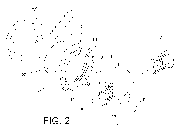
Figure 2 shows an exploded view of the device with the improvements of the
invention.
Figure 3 shows a perspective view of the rotatable body forming part of the
supporting element.
Figure 4 shows a plan view of the ring base that forms part of the supporting
element.
Figure 5 shows a cross-section view of the ring base, along the A-A section of
figure 4.
CA 02795606 2012-10-05
Figure 6 is a view that essentially shows the three strands of a strap for
fastening
the supporting element to the skiing boot, said strands meeting in a central
zone of the
supporting element.
Figure 7 is a view that essentially shows the fastening of the device of the
invention to the corresponding boot.
Figure 8 shows a cross-section view of the assembly of the device with the
improvements of the invention.
Figure 9 shows a view of the application of the device of the invention with
its
improvements.
DESCRIPTION OF A PREFERRED EMBODIMENT
Following the numbering adopted in the drawings, the ski transportation device
with the improvements of the invention is determined on the basis of a
supporting
element 1 having a movable part determined by a rotatable body 2 and a fixed
part
determined by a ring base 3 that is fixed to the outer side of skiing boots 4
using a strap
5 that embraces the corresponding boot 4 in three different directions.
The rotatable body 2 incorporates a receptacle for holding the rear end
section of
the skis 6, said receptacle being delimited by a frontal elastic rim 7 and two
adjustable
runners 8 that can be adapted to the width of the skis 6.
The adjustable runners 8 comprise an angular configuration wherein the larger
branches thereof are coupled to rails 9 in a dovetail, so that they adapt to
the width of
the skis 6, the latter butting at their edges against the smaller branches of
said
adjustable runners 8.
Stable securing of the adjustable runners 8 is achieved by means of bolts 10
that
pass through longitudinal grooves 11 in said runners 8 and also through
frontal holes 12
placed in a circular base 13 of the rotatable body 2, finally threading said
bolts 10 to
nuts 14 housed in notches in the circular base 13 of said rotatable body 2, in
such a
way that tightening the bolt 10 and the nut 14 ensures the stable position of
the
adjustable runners 8 adapted to the width of the respective ski 6. The
longitudinal
grooves 11 of the adjustable runners 8 are affected by bevelling to adapt to
the head of
the bolts 10 and thereby prevent it from jutting outwards frontally to avoid
collision with
the skis 6 when being accommodated by their rear end sections into the
rotatable body
2.
The elastic rim 7 starts from the edge of the circular base 13 of the
rotatable body
2 delimiting an inner gap 15 where the end portion (tail) of the ski 6 is
housed, at the
same time as the elastic rim 7 has a bottom section 16 where the outer edge of
the ski 6
CA 02795606 2012-10-05
6
rests. This inner gap 15 is delimited by the bottom section 16 and an
enveloping
intermediate section 16' which also forms part of the aforesaid elastic rim 7.
Meanwhile, the elastic rim 7 has a top arched section 17 close to the outer
face
of the circular base 13 of the rotatable body 2 in such a way that when the
tail of the ski
6 is accommodated in the corresponding receptacle of the rotatable body 2, its
insertion
begins through a conical mouth 18 in the form of a funnel delimited between a
curved
end portion 19 forming part of the elastic rim 7 and a bevelled portion 20
placed in a top
zone of the circular base 13, in such a way that when the ski 6 is moved
downwards,
the rim 7 yields elastically allowing the ski 6 to penetrate until resting on
the bottom
section 16 of the aforesaid elastic rim 7 that will press frontally against
the
accommodated ski 6 improving securing thereof.
The circular base 13 of the rotatable body 2 incorporates on its rear face
angular
tabs 21 wherein their free portions engage by snap fitting into a
circumferential slot 22
of the ring base 3, thereby ensuring the coupling between these two parts 2
and 3 of the
supporting element 1, as well as the rotational mobility of the rotatable body
2.
On a separate note, the ring base 3 of the supporting element 1 incorporates
three lateral openings 23 angularly equidistant from each other through which
the three
strands 5a-5b-5c of the fastening strap 5 of the supporting element 1 pass, in
such a
way that those three strands meet in the middle of the ring base 3, an
intermediate disk
24 being inserted between the meeting point of said strands and the rotatable
body 2,
embedded in a housing of the annular ring 3 covering its central gap.
Fastening of the supporting element assembly 1 to the side of the boot 4 is
ensured by means of the incorporation of a ring 25 of soft anti-slip material,
such as
neoprene foam, which is fixed to the ring base 3, whereupon this ring 25 will
adjust to
the irregularities and different profiles presented by the different ski boots
4 on this side
resting zone.
As shown in figure 6, in an embodiment to fasten the supporting element 1, the
strap 5 follows a path that has the three strands 5a-5b-5c angularly
equidistant from
each other as mentioned previously, which meet in a central zone of the ring
base 3 of
the supporting element 1. One of the strands passes underneath the sole of the
boot 4.
To this effect, a guiding piece 26 is incorporated with two end portions 27 at
120
through which two of the strands 5b-5c of the strap 5 pass, which meet in a
central
section that engages in a ring 28 which engages in turn the third strand 5a of
the strap
5, which has an adherent surface 29 to ensure the fastening of the supporting
element 1
to the boot 4 (figure 7) after making it pass through an outer ring 30 located
on the inner
side of the corresponding boot 4.
CA 02795606 2012-10-05
7
The meeting of the three strands 5a-5b-5c could present another different
structure, such as the one shown in figure 2 which shows a meeting of two
different
straps.