Note: Descriptions are shown in the official language in which they were submitted.
CA 02795633 2012-11-14
1
Blind Rivet Element
Description
The invention relates to a blind rivet element having a setting head and a
shank. The shank has a female
thread or a receptacle for a threaded bolt at its end distal to the setting
head, and a deformation section
between the female thread or the bolt receptacle and the setting head. The
setting head has a larger
outside diameter than the shank. After deformation of the shank and creation
of the closing head, the
deformation section has a bead that extends on the exterior circumference of
the shank.
Blind rivet elements of this type are designed for example as blind rivet nuts
or blind rivet threaded
bolts.
EP 1 918 596 describes a blind rivet element of the type cited in the
foregoing.
Blind rivet elements have proven appropriate for fastening tasks in which a
screw connection is required
in the area of thin-walled materials, for example metal sheets, into which it
is not normally possible to
cut a loadable thread. Blind rivet elements form the mating retainer flange ¨
closing head by forming a
bead, that is, a material fold. The lower the material strength of a thin-
walled article, especially metal
sheet, with which the blind rivet element of defined dimensions is to be
connected, the greater the
outer diameter of the bead. However, the radial extension of the bead is
always relatively small with
respect to the outer diameter of the shank of the blind rivet element.
DE 198 08 685 Al also describes a blind rivet element of the type cited in the
foregoing. It is embodied
as a blind rivet nut. In this blind rivet nut, the area in the deformation
section where the closing head
begins to be formed is not defined. Instead, it depends in particular on the
mounting arrangement.
When the blind rivet nut is being set, a circumferential bead forms in the
area of the deformation
section. This bead is thus closed in the circumferential direction of the
shank and consequently
describes a complete circle. The thin-walled article, especially metal sheet,
is fixed between this
circumferential bead and the setting head.
In order to attain a defined design of the circumferential bead, EP 1 918 596
Al provides that the shank
has a weakening in the shank wall in a central circumferential area of the
deformation section. This
weakening is attained in particular by means of a plurality of holes in the
shank. After the blind rivet
element has deformed, a closing head in the shape of a circumferential bead
forms in a defined manner
due to the weakening of the shank wall.
US-A-3,789,728 describes another type of blind rivet element. In this case,
the blind rivet element is
embodied as a blind rivet nut. Its shank is provided with a plurality of
through-slits arranged parallel to
CA 02795633 2012-11-14
2
the center longitudinal axis of the shank. Consequently, no bead-like closing
head is created when the
blind rivet element is being set. Instead, rosettes are bent out of the
material. These rosettes have quite
a large radial extension compared to a bead. A wedge-shaped intermediate space
forms between
adjacent rosettes. Because of the large radial extension of the deformed
sections of the blind rivet nut,
its outer radial position on the metal sheet is quite a distance from the
center longitudinal axis of the
shank.
The described blind rivet elements may be connected to thin-walled articles,
especially metal sheet, only
if there is sufficient room behind the thin-walled element for the blind rivet
element to deform radially
outward in the area of its deformation section when the blind rivet element is
set. This is particularly
true for the embodiment of the blind rivet element that forms rosettes when it
is set.
The object of the invention is to create a blind rivet element in which
fundamentally it is not necessary
for the closing head to be designed with a bead that describes a complete
circle, or in which it is not
desired that the closing head be designed with a bead that describes a
complete circle because it would
collide with another article.
For attaining this object, a blind rivet element is suggested according to the
features of the type of
element cited in the foregoing. In this blind rivet element, the shank is
configured such that in the area
of the shank in which a bead is not supposed to form, the bead is prevented
from forming by material
being removed from the shank.
The inventive blind rivet element may thus be used in two basic areas. In one
case, it would not be
possible to use a conventional blind rivet element because a circumferential
bead would form when the
blind rivet element was being set, but this bead cannot form because there is
an article in the expansion
path of the shank when the blind rivet element is being set. In this case the
blind rivet element cannot
be set unless it is configured such that it does not deform in the direction
of the article disposed
immediately adjacent to the blind rivet element. In the other case, there
would in fact basically be
sufficient room for a circumferential bead when the blind rivet element was
set. However, for certain
reasons this space should not be completely occupied. So, when the blind rivet
element is set, it is
enough to create a bead that is only a partial circle. Therefore, no bead
forms in the remaining part of
the circle. Such a bead design in a blind rivet element may be advantageous,
for example, if the blind
rivet element is acted upon by forces that have a substantial radial
component. In this case it is not of
decisive importance that a maximum clamping surface is created between bead
and setting head via a
circumferential bead.
In the inventive blind rivet element, the shank is thus configured such that
removing material from the
shank prevents formation of the bead in the area of the shank in which it is
desired that the bead does
not form.
As long as it is assured that the bead does not form in the area of interest
of the shank, material may be
removed from the shank in a variety of ways, and different amounts of material
may be removed from
the shank.
CA 02795633 2012-11-14
3
During production of the blind rivet element, material may be removed from the
shank in the area of
interest in that for example a hole or a recess is added to the shank when the
blank is pressed.
Alternatively, during production of the blind rivet element material may be
removed from the shank in
the area of interest by mechanical machine, for instance. Often removing
material in the area of interest
of the shank will attain the inventive purpose even though the removal of the
material does not lead to
a through-hole being formed in the shank. Just this measure may assure that in
this area the shank has
so little material that no bead can form in this area when the blind rivet
element is being set. It is
considered preferable because this is the simplest way to prevent the bead
from forming by removing
material from the shank. The shank has a hole, especially a hole that has a
circular cross-section prior to
the blind rivet element being set. As described, what this hole attains,
especially the hole that has a
circular cross-section prior to the blind rivet element being set, is that
there is not enough material
available to contribute to forming a bead when the blind rivet element is set.
Therefore no bead forms
in this area of the shank.
Material is removed in the area of the shank, and thus the wall thickness of
the shank wall is reduced
relative to the adjacent area of the shank wall, which is not reduced in
thickness. This allows bead
formation to be prevented in a defined shank area. Specifically, bead
formation may be prevented in the
area in which the material of the shank has been reduced. Removing material
from the shank at one or
two locations on the shank makes it possible to define one or two shank areas
in which no bead is
produced when the blind rivet element is set. When material is removed in the
area of one location on
the shank, no bead is produced on one side of the shank. If there are two
areas in which the material is
removed from the shank, especially areas that are arranged on outer sides of
the shank, this forms two
areas in these outer sides of the shank in which no bead forms.
This configuration of the blind rivet element makes it possible for example to
use the blind rivet
element, if it is to be mounted, after it has been inserted through a hole in
a floor of a channel-shaped
component, when the channel-shaped component has a limiting wall parallel to
the longitudinal
extension of the shank. It is possible to set the blind rivet element in the
area of the limiting wall
because material from the shank has been removed in the area of the limiting
wall and when the blind
rivet element is being placed the shank does not deform, or deforms only in an
insignificant manner, in
the direction of the limiting wall. It is only in this area of the limiting
wall that no bead is formed. The
bead is present in the remaining circumferential area of the shank after the
blind rivet element has been
set. Thus the blind rivet element is securely attached to the thin-walled
component, and in the area of
the floor of the channel-shaped component, but it is also positioned near the
limiting wall.
If the channel-shaped component is very narrow, so that two limiting walls are
arranged relatively close
to one another, it is provided that the blind rivet element has the shank with
reduced material thickness
on the outer sides. Thus the material is removed from these outer sides of the
shank. This prevents the
bead from forming on these two outer sides of the shank. The bead is prevented
from forming in
particular in that the shank has a hole. Prior to the setting of the blind
rivet element, the extension of
the hole in the axial direction of the shank is at least equal to the
extension of the deformation section
in the axial extension of the shank after the blind rivet element has been
set. In particular this ensures
CA 02795633 2012-11-14
4
that no bead can form in this area of the shank. This is because there is no
material available for
contributing to forming the bead because material was removed when the hole
was made.
Additional features of the invention are provided in the subordinate claims,
the description of the
figures, and the figures themselves. It should be noted that all individual
features and all combinations
of individual features are essential to the invention.
The invention is depicted using a plurality of embodiments for different
applications in an exemplary
manner without being limited thereto.
Fig. 1 shows as a first exemplary embodiment of the invention,
providing a view (right half)
and a center longitudinal section (left half) of a blind rivet element
embodied as a blind
rivet nut;
Fig. 2 shows a view and a center longitudinal section of the blind
rivet nut from Fig. 1, but
rotated 900 about its center longitudinal axis compared to the depiction in
Fig. 1.
Fig. 3 shows a center longitudinal section of the arrangement of a thin-
walled article (metal
sheet) and the blind rivet nut from the embodiment in Figs. 1 and 2 after the
blind rivet
nut has been set;
Fig. 4 shows a view of the arrangement according to Fig. 3, seen from
the direction of the
arrow IV in Fig. 3;
Fig. 5 shows the blind rivet nut from the embodiment in Figs. 1 and 2,
inserted into a leg of an
L-shaped article that defines a cavity;
Fig. 6 shows the arrangement from Fig. 5, seen from the direction of
the arrow VI in Fig. 5;
Figs. 7 and 8 show a second exemplary embodiment of the blind rivet element
embodied as a blind
rivet nut, shown in a view and a section as in Figs. 1 and 2;
Figs. 9 and 10 show the arrangement of the blind rivet nut and the thin-walled
article (metal sheet) as
shown in Figs. 3 and 4, wherein Fig. 10 is a view X according to Fig. 9;
Fig. 11 and 12 show an arrangement of the blind rivet nut according to the
embodiment in Figs. 7 and
8 and a component cooperating therewith in views like those in Figs. 5 and 6,
wherein
the component has a floor and two parallel limiting walls, and Fig. 12 is a
view XII
according to Fig. 11;
Figs. 13 through 19 are various views of the blind rivet nut embodied
according to Figs. 7 and 8 and
arranged according to Figs. 9 and 10, including a basic depiction of a blind
rivet nut for
clarifying the geometric relationships and forces, with dimensions provided;
Fig. 20 shows the blind rivet nut in accordance with the exemplary
embodiment according to
Figs. 7 and 8, in a depiction corresponding to these figures;
CA 02795633 2012-11-14
5
Fig. 21 shows the blind rivet nut according to the embodiment in Fig. 20
riveted to a
compressible material;
Fig. 22 is a section through the arrangement according to the line XXII
in Fig. 21;
Figs. 23 through 28 show a basic exemplary embodiment of the blind rivet
element embodied as a
blind rivet threaded bolt in depictions like those for the exemplary
embodiment in Figs.
7 through 12.
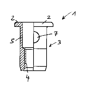
Figs. 1 and 2 illustrate a first embodiment of the invention, which is a blind
rivet nut 1 before it is set.
The blind rivet nut 1 has a setting head 2 and a shank 3. The shank 3 is
provided with a female thread 4
in the area of its end distal to the setting head. The shank 3 is provided
with a deformation section 5
between the female thread 4 and the setting head 2. Fundamentally this
deformation section 5 extends
up to the setting head 2, since the blind rivet nut 1 could deform in this
area if a tensile force is
introduced into the female thread 4. In practice, since the blind rivet nut is
to be connected to a plate-
shaped component 6, especially a metal sheet 6, this deformation section 5
extends only from the area
of the female thread 4 to the side of the plate-shaped component 6 that faces
away from the setting
head 2.
The setting head 2 has a larger outer diameter than the shank 3. The outer
diameter of the shank 3 is
constant. The inner diameter of the shank 3 in the area of the deformation
section 5 is also constant and
is equal to the inner diameter of the setting head 2. The inner diameter of
the female thread 4 is smaller
than the inner diameter of the shank 3 in the area of the deformation section
5. The aforesaid does not
apply to the blind rivet nut 1 when it has been deformed.
The blind rivet nut 1 in the area of its deformation section 5 is provided
with a hole 7 that has a circular
cross-section and that passes through the shank 3. For example, in the blind
rivet nut 1 the outer
diameter of the shank 3 is 9 mm and the diameter of the hole 7 is 4 mm. The
axis of rotation of the hole
7 intersects the center longitudinal axis of the deformation section 5 of the
shank 3 in the blind rivet nut
1 that has not be set.
The shank 3 of the blind rivet nut 1 is inserted through a hole 9 that has a
circular section in the metal
sheet 6. The outer diameter of the shank 3 of the blind rivet nut 1 is
slightly smaller than the diameter of
the hole 9. The setting head 2 of the blind rivet nut 1 is positioned on the
metal sheet 6. Then a
threaded mandrel (not shown) is introduced in the area of the setting head 2
into the blind rivet nut 1.
From there it is screwed into the female thread 4. As illustrated for the
blind rivet nut 1 that is already
set in Fig. 3, the blind rivet nut 1 is fastened by means of a blind rivet nut
setting device that has the
threaded mandrel and is placed on the setting head 2. When the blind rivet nut
1 is being set, a force is
introduced via the female thread 4 into the blind rivet nut 1 with the setting
head 2 fixed axially. This
causes the blind rivet nut 1 to deform in the area of the deformation section
5. A bead 10 forms.
However, as can be seen from the depiction in Fig. 4, the bead 10 is not
continuous and does not
describe a complete circle. On the contrary, it is interrupted. Due to
material being removed from the
CA 02795633 2012-11-14
6
shank 3 by the embodiment of the hole 7, when the blind rivet nut 1 is set
there is no material or only
very little material available in this area of the shank 3 to form a bead in
the area of this hole 9 when the
blind rivet nut 1 is set. The radial outer contour of the bead 10 extends
across an angle of approximately
270 relative to the center longitudinal axis 8 of the blind rivet nut 1.
As can be seen from the depiction in Fig. 4, after the blind rivet element has
been set the side of the
deformation section 5 in the area of which no bead 10 forms is essentially a
limiting surface that is
arranged perpendicular to the metal sheet 6 and runs tangential to the shank 3
in the area of the outer
contour of the shank 3 that faces away from the female thread 4. As can be
seen especially in the
depictions in Figs. 5 and 6, this makes it possible to attach the blind rivet
nut 1 in the embodiment
shown in Figs. 1 and 2 to an article that has the plate-shaped component 6 and
a limiting wall 11 that
runs perpendicular thereto. This limiting wall 11, the plate-shaped component
6, and other components
(not shown) form in particular a cavity 12. The shank 3 of the blind rivet nut
1 is inserted through the
hole 9 into the plate-shaped component 6. The shank 3 extends beyond the
component 6 into the
cavity. The hole 7 is arranged immediately adjacent to the inner surface 13 of
the limiting wall 11. When
the blind rivet nut 1 is being set, that is, when the deformation section 5 is
being deformed against the
component 6, the area 15 facing the limiting wall 11 does not deform. This is
because, due to the
embodiment of the shank 3 with the hole 7, there is not enough material
present there to form the
bead 10 adjacent to the limiting wall 11.
In this context it does not matter if there are slight projections 14 in the
end areas of the bead 10 when
the blind rivet nut 1 deforms. In the area of these projections the blind
rivet nut 1 contacts the limiting
wall 11 or the projections 14 dig slightly into the limiting wall 11. The
element formed by the limiting
wall 11 and the leaf-shaped component 6 preferably comprise aluminum or
plastic.
The embodiment of the blind rivet nut 1 in Figs. 7 and 8 is distinguished from
the embodiment in Figs. 1
and 2 only in that, instead of one hole 7, there are two holes 7 with the
identical dimensions and
arrangement. They are arranged on the outward facing sides of the shank 3 in
the area of the
deformation section 5. The center longitudinal axis of the holes 7 thus
intersects the center longitudinal
axis of the deformation section 5 at a right angle, relative to the unset
blind rivet nut 1. Consequently,
when the blind rivet nut 1 is set this leads to the bead 10 being interrupted,
not once as it is with the
exemplary embodiment in Figs. 1 through 6, but twice. Thus two areas 15 are
formed on the outer sides
of the shank 3 with the bead 10 therebetween. This design of the blind rivet
nut 1 with the two areas 15
in which the material in the shank 3 is removed by the creation of holes 7 to
prevent formation of the
bead makes it possible to attach the blind rivet nut 1 to a channel-shaped
component that forms a
cavity. The channel-shaped component is formed by the plate-shaped component 6
and two limiting
walls 11 that are arranged parallel to one another and perpendicular to the
plate-shaped component 6.
Despite the small distance between the two limiting walls 11, which is clearly
smaller than the diameter
of the blind rivet nut 1 in the area of the deformed deformation section 5,
the blind rivet nut 1 may be
arranged between the two limiting walls 11 and set there. The deformation of
the blind rivet nut 1 here
occurs only in the longitudinal extension of the channel formed between the
limiting walls 11.
CA 02795633 2012-11-14
7
Figs. 1 and 3 and Figs. 7 and 9 illustrate that each hole 7 in the exemplary
embodiments has a diameter
such that its extension in the axial direction of the shank 3 prior to the
blind rivet element 1 being set is
at least equal to the extension of the deformation section 5 in the axial
direction of the shank 3 after the
blind rivet element 1 has been set.
Instead of the blind rivet element being designed as a blind rivet nut 1, the
blind rivet element may
certainly be designed as a blind rivet threaded bolt. In this case the shank,
in the area distal to the
setting head, has a receptacle for a threaded bolt. It has the deformation
section between the
receptacle for the threaded bolt and the setting head.
Figs. 13 and 14 depict a blind rivet nut that is embodied according to the
exemplary embodiment in Figs.
7 and 8. In the actual test arrangement, this blind rivet nut 1 has two
opposing holes 7, each having a
diameter of 4.2 mm. The shank 3 has an outer diameter of 9 mm. This can be
seen in Fig. 13. As can be
seen in Fig. 14, because of these geometric relationships, seen over the arc
of the shank 3 in the area of
the deformation section 5, the computed opening in the non-deformed blind
rivet nut 1 is 4.2 mm and
each deformation section 5 between the two holes 7 is 7.96 mm. The takeout
angle in the area of each
hole 7 is 55.64 .
Fig. 15 depicts the blind rivet nut 1 riveted into the plate-shaped component
6 and having a bead 10. In
practice the outer diameter of the bead is for example 13 mm, as illustrated
in Fig. 15. Fig. 16 illustrates
actually expected dimensions in the area of the bead 10 when the nut is set.
It may be expected that
when the nut is set the 55.64 takeout angle of the hole will remain the same
in the area of the bead 10,
as well. This would mean that the takeout angle of the deformed hole 7 on the
circumference of the
bead 10 would have to be 6.7 mm. Consequently the outer arc of each bead 10
would be 11.5 mm.
Surprisingly, however, in practice this is not the case. Instead, Fig. 17
essentially depicts what actually
happens. The takeout angle (55.64 ) is significantly enlarged, and the
dimension of only 9.8 mm
according to Fig. 17 results instead of the dimension 11.5 mm according to
Fig. 16. Consequently both
beads 10 in Fig. 17, which correspond to those in Fig. 10, are arranged
essentially on opposing sides of
the blind rivet nut 1.
Figs. 18 and 19 provide possible explanations for the unexpected deformation
of the bead 10 in Fig. 17.
Fig. 18 illustrates that uniform deformation forces act on the circumference
of the deformation section
and form the bead in a blind rivet nut 1 in which the shank 3 does not have
any holes 7. These forces
are shown across the complete circle. Consequently, when such a blind rivet
nut 1 is deformed the
resulting bead on the circumference is precisely uniform. Fig. 19 illustrates
that when the shank 3 is
designed with the two holes 7, although it is entirely possible for only one
hole 7 to be provided, the
deformation forces act significantly more strongly diametrically. Only slight
forces can act in the
direction of the two holes 7. This seems to lead to the embodiment of the bead
10 or beads 10 in Fig.
17.
Fig. 20 illustrates the blind rivet nut 1 according to the exemplary
embodiment in Figs. 7 and 8. As can
be seen in the depiction in Figs. 21 and 22, this blind rivet nut 1 is riveted
to a thick-walled component 6
that comprises a compressible material, e.g. wood. Since the deformation
section 5 of the blind rivet nut
CA 02795633 2012-11-14
8
1 is disposed in the area of the component 6, when the blind rivet nut 1 is
being set this leads to the two
beads 10 expanding into the compressible material. As can be seen in the
depiction in Fig. 22, the
embodiment of the two beads 10 provides an anti-rotation element for the blind
rivet nut 1. This anti-
rotation element would of course also be provided if only one bead 10 were to
be formed, as in the
exemplary embodiment of the blind rivet nut 1 in Fig. 1.
Figs. 23 through 28 show an embodiment of the blind rivet element as a blind
rivet threaded bolt 1 and
its use with a plate-shaped component 6, as depicted in Figs. 25 and 26, and
with a component 6 that
has parallel limiting walls 11, as in Figs. 27 and 28. Parts that coincide
with the embodiments in Figs. 7
through 12 are marked with the same reference numbers in Figs. 23 through 28.
Fig. 26 is a view
according to the arrow XXVI in Fig. 25. Fig. 28 is a view according to the
arrow XXVIII in Fig. 27.
As can be seen from the depiction of the blind rivet element 1, which is
embodied as a blind rivet
threaded bolt according to the depictions in Figs. 23 through 28, the shank 3
of the blind rivet threaded
bolt has a receptacle 16 for a threaded bolt 17 in the area of its end distal
to the setting head 2. It has
the deformation section 5 between the receptacle 16 and the setting head 2.
Refer to the information
provided in the foregoing regarding the embodiment in Figs. 7 through 12 for a
more detailed
description of the exemplary embodiment in Figs. 23 through 28.