Note: Descriptions are shown in the official language in which they were submitted.
CA 2795685 2017-03-17
REBOUND-DAMPENING AND ENERGY ABSORBING HEADGEAR LINERS WITH
POSITIONING FEATURE
Related Applications
[0001] This application is the national phase of WO 2011/133589, filed
April 19, 2011.
Technical Field
[0002] The disclosure relates to personal protective equipment, and in
particular to fluid-
containing liners adapted for use with a wide variety of designs of protective
headgear.
Background
[0003] Liners are used in conjunction with protective headgear, such as
helmets designed
for use with various sports and other outdoor activities, primarily to be
interposed generally
between the interior surface of the headgear and a wearer's head. Most liners
are configured for
wearer comfort, but some may also or alternatively serve a protective
function, such as by
including cushions, pads, or other materials to soften or prevent the impact
of the wearer's head
against the interior of the headgear, such as when the headgear exterior is
subject to an impact
or other force.
[0004] Many head or brain injuries incurred while wearing protective
headgear, however,
are caused or exacerbated by what may be referred to as a "rebound effect": in
the event of a
sudden force delivered to the headgear, the wearer's head will tend to
initially lurch toward the
point of impact and then recoil or rebound from the headgear interior (or
cushioning system)
away from the point of impact, in certain instances, it is the energy
associated with the rebound
effect, sometimes regardless of whether the initial impact is cushioned, that
is primarily
responsible for the severity of head injuries sustained while wearing
headgear.
[0005] Headgear liners or protective systems that include a plurality of
fluid-filled cushions
or chambers may be found, for example, in US5720051, US4566137, US4375108,
US43707S4.
US4354284, US7774866. and US4287613. In some of these disclosures, the fluid-
filled
cushions are joined together to allow the flow of fluid from one cushion to an
adjoining one, such
as to absorb and/or distribute the energy from an impact to the headgear over
a large area of
the wearer's head. However.
Page 1
CA 02795685 2012-10-04
WO 2011/133589 PCT/US2011/033107
none address the rebound effect as explained above. Moreover, although the
headgear with which some
of these liners are used may employ a chinstrap or other device to orient the
headgear on a wearers
head, none of the liners themselves include such a feature. The complete
disclosures of the
aforementioned publications are hereby incorporated by reference for all
purposes.
Summary
[0006] Illustrative embodiments of liners adapted for use with headgear,
generally in a manner in
which the liner is interposed between the interior surface of the headgear and
a wearers head received
therein, include a plurality of fluid cells formed from a flexible, fluid-
impermeable material, each fluid cell
adapted to receive and store fluid, such as air, the plurality of fluid cells
further including a group of
networked fluid cells which each communicate with at least one other via a
fiuid passageway, and a
group of discrete, non-networked fluid cells interspersed among the networked
fluid cells. In such
embodiments, when the fluid pressure in the fluid cells is at least a
predetermined minimum value, such
as equivalent to atmospheric pressure, the discrete fluid cells are configured
to position the headgear on
a wearers head and to maintain an initial spaced relationship between the
user's head and the interior
surface of the headgear, and the fluid passageways are configured to equalize
fluid pressure across the
networked fluid cells of the group responsive to a force delivered thereto,
such as to distribute and
thereby dissipate such a force over a larger region of the wearers head than
that corresponding to the
initial point or location of impact. In such embodiments, the networked, or
interconnected, fluid cells are
adapted to dampen the tendency of the wearers head to rebound from an impact
location by laterally
distributing fluid from the networked cells at or near the impact location (or
at or near the portion of the
finer corresponding to the impact location on the headgear) to other networked
fluid cells that are
disposed at one or more locations on the liner that are generally opposed to
the impact location.
[0007] In some embodiments, the liner is formed from two or more
superimposed plies of a
flexibie, fluid-impermeable material, with the adjacent surfaces thereof being
seated at regions internally
of their peripheries to form the 'fluid cells and passageways. In some
embodiments, the fluid cells are
arranged in a single layer. In such embodiments, each of the discrete fluid
cells may be laterally
encompassed by at least one networked cell, or a combination of at least two
networked cells and the
fluid passageway(s) interconnecting them. In some embodiments, the cross-
sectional height of the
Page 2
CA 02795685 2012-10-04
WO 2011/133589 PCT/US2011/033107
discrete fluid ce,ils, as defined by the extent to which the discrete fluid
cells protrude into the concavity
formed by the liner, is greater than that of the networked fluid cells, such
as to maintain a spaced
relationship between the wearer's head and the headgear, or even between the
wearer's head and the
networked cells.
[0008] In some embodiments, some of the fluid cells may be configured to
release fluid responsive
to a predetermined threshold fluid pressure, such as by rupturing, by
transferring fluid via a passageway
or valve configured to only allow fluid transfer once the threshold fluid
pressure is reached, and so forth.
Some embodiments may include reserve fluid cells that are initially empty, but
are configured to accept
fluid transferred from other fluid cells responsive to the threshold fluid
pressure.
[0009] In some embodiments, some of the fluid passageways may be provided
with means to
restrict fluid flow to a predetermined flow rate, or to establish preferential
fluid transfer between certain
networked cells, such as cells in opposed regions of the liner, for example to
facilitate the rebound-
dampening effect of the liner.
[0010] The fluid cells in some liners may be completely sealed from the
ambient atmosphere,
whereas some liner embodiments may be valved, such as by including one or more
valve members
adapted to allow fluid to flow into or out of one or more fluid cells. Such
embodiments may further include
pressurizing means for selective fluid movement into or out of the liner, such
as by means of an integral
or removably attachable pump.
[0011] In some embodiments, a liner is attached to the interior surface of
a helmet having an
impact-resistant exterior surface and adapted to be disposed between the
interior surface and a wearer's
head. In such embodiments, the liner may be removably positionable within the
helmet via a plurality of
fasteners, which may optionally be arranged in a configuration defining a
predetermined orientation for
positioning the liner relative to the helmet,
[0012] The concepts and components listed above are clarified with
reference to the
accompanying drawings and detailed description below.
Page 3
CA 2795685 2017-03-17
[0012a] According
to one aspect of the invention, there is provided a liner for protective
headgear adapted to be interposed between the interior surface thereof and a
wearer's head
received therein, the liner comprising:
a plurality of fluid cells formed from a flexible, fluid-impermeable material,
each fluid cell
adapted to receive and store fluid therein, the plurality of fluid cells
further including:
a group of networked fluid cells extending in a hub-and-spoke arrangement
across the liner, where:
the networked fluid cells define the hubs in the hub-and-spoke
arrangement, the networked fluid cells being spaced from one another;
elongate fluid passageways define the spokes in the hub-and-spoke
arrangement, the elongate fluid passageways interconnecting two networked
fluid cells; and
the networked fluid cells and the elongate fluid passageways cooperate to
equalize fluid pressure across the networked fluid cells responsive to a force
delivered to a
networked fluid cell by communicating fluid through the elongate fluid
passageways between
the group of networked fluid cells; and
a group of discrete, non-networked fluid cells interspersed among the
networked
fluid cells;
wherein at least some of the discrete fluid cells position the headgear on a
wearer's
head and maintain an initial spaced relationship between the user's head and
the interior
surface of the headgear when the fluid pressure in the networked fluid cells
is at least a
predetermined minimum value.
[0012b] According
to another aspect of the invention, there is provided a liner for
protective headgear adapted to be interposed between the interior surface
thereof and a
wearer's head received therein, the liner comprising;
a plurality of spaced fluid cells formed from a flexible, fluid-impermeable
material, each
fluid cell adapted to receive and store fluid therein, the plurality of fluid
cells further including:
a group of networked fluid cells which each communicate with at least one
other
spaced networked fluid cell via an elongate fluid passageway extending
therebetween, each
networked fluid cell defining a distinct, fluid-restrictive wall substantially
enclosing the interior of
the fluid cell, each wall being initially spaced from the walls of other
networked fluid cells; and
a group of discrete, non-networked fluid cells interspersed among the
networked
fluid cells;
Page 3a
CA 2795685 2017-03-17
wherein:
the networked cells are ring-shaped and the discrete, non-networked cells are
encompassed thereby; and
when the fluid pressure in the fluid cells is at least a predetermined minimum
value, at
least some of the discrete fluid cells are configured to extend from the
interior surface toward
the wearer's head a distance sufficient to abut the wearer's head to position
the headgear on a
wearer's head and to maintain an initial spaced relationship between the
user's head and the
interior surface of the headgear, and the fluid passageways are configured to
equalize fluid
pressure across the networked fluid cells of the group responsive to a force
delivered thereto by
communicating fluid through the elongate fluid passageways extending between
the group of
networked fluid cells.
Page 3b
CA 02795685 2012-10-04
WO 2011/133589 PCT/US2011/033107
Brief Description of the Drawings
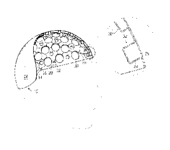
[0013] FIG. 1 shows a side view of an illustrative embodiment of a headgear
liner constructed in
accordance with the present disclosure, partially cut away to show the
interior surface and a cross-section
thereof
[0014] FIG. 2 shows a detail view of a portion of the fluid cell pattern on
the interior surface of the
headgear liner of FIG. 1.
[0015] FIG. 3 shows a detail view of another configuration of a fluid cell
pattern of another
illustrative embodiment of a headgear liner constructed in accordance with the
present disclosure.
[0016] FIG. 4 shows a cross-sectional view of the liner of FIG. 1
incorporated into a helmet that is
worn by a user.
[0017] FIG. 5 shows a cross-sectional view similar to that shown in FIG. 4,
but in which the user's
head has moved forward inside the helmet, such as in response to an impact
force delivered to the front
exterior surface thereof.
[0018] FIG. 6 shows a detail view of a configuration of a fluid cell
pattern of another illustrative
embodiment of a headgear liner constructed in accordance with the present
disclosure, in which some of
the fluid passageways are adapted to provide a preferential fluid flow
pathway.
[0019] FIG. 7 shows a detail view of a configuration of a fluid cell
pattern of another illustrative
embodiment of a headgear liner constructed in accordance with the present
disclosure, in which some of
the fluid passageways include fluid restricting means.
[0020] FIG. 8 shows a three-dimensional view of an illustrative embodiment
of a headgear liner
constructed in accordance with the present disclosure, in which the liner is
provided with pressurizing
means.
Detailed Description
[0021] The protective liner of the present disciosure may find utility in
several areas and design
emphasis may shift depending on the application. For example, the liner is
generally adapted for use with
a protective headgear, such as a helmet, to be interposed between the interior
surface of the headgear
and a wearer's head received therein. In such embodiments, the liner may take
a form appropriate to the
interior configuration of the headgear, such as to provide coverage to the
areas and/or portion of the
Page 4
CA 02795685 2012-10-04
WO 2011/133589 PCT/US2011/033107
wearer's head that the headgear covers or protects. Liners constructed in
accordance with this disclosure
may, in some embodiments, be suitable for use with other pieces or types of
personal protective gear,
such as those used in sports or other 'activities to protect other parts of
the wearer's body. Therefore, it is
intended that although the illustrative embodiments of a liner described
herein may be for use with a
specific type of protective helmet or other headgear used in connection with a
particular activity, the
present invention has application in other areas and may be adapted to such
applications without
departing from the scope of this disclosure.
[0022] Referring initially to FIG. 1, an illustrative embodiment of a liner
for protective headgear
constructed in accordance with the present disclosure is indicated generally
at 10, and is shown to
comprise a plurality of fluid cells 20 that are each adapted to receive and
store a fluid, such as air,
therein, and also a plurality of fluid passageways 22 that join some of the
cells 20. The cells 20 and
passageways 22 are at !east partially formed from a flexible, fluid-
impermeable material and are shown to
be arranged in a single layer generally defining a shape having a concavity
suitable to receive at least a
portion of a wearer's head.
[0023] In particular, the cells 20 and passageways 22 of the illustrative
liner 10 are formed from
two superimposed plies 24, 26 of such a material, with the adjacent surfaces
thereof sealed at regions
internally of their peripheries to form the fluid cells and passageways.
Although other configurations
having two or more plies are possible, in the liner 10, the "inner" ply 24
forms the interior surface of the
liner 10 which forms the concavity, and includes the fluid cells 20 and
passageways 22, which protrude or
project generally into the concavity. The "outer" ply 26 forms a generally
smooth exterior surface of the
liner 10.
[0024] As is evident from the shape and context, the liner 10 is configured
for use with protective
headgear, such as any of various types of helmets suitable for a range of
sports and other activities,
including football helmets, baseball helmets, motorcycle or motocross helmets,
bicycle helmets, skiing
and snowboarcling helmets, military helmets, and so forth. Liner 10 may be
incorporated into a helmet or
other headgear, generally to be interposed between the wearer's head and the
helmets interior. As such,
either or both of the exterior and interior surfaces of the liner may be
provided with additional components
or features as appropriate to the applic2tion. For example, the liner in some
embodiments may be
Page 5
CA 02795685 2012-10-04
WO 2011/133589 PCT/US2011/033107
removably positionable within a helmet or permanently affixed thereto, such as
via one or more fastening
systems that secure the liner directly to the interior surface of the helmet
and/or to a secondary
cushioning system on the helmet interior, such as hook-and-loop fasteners,
adhesives, snaps, and so
forth. Although the liner may be worn with the interior surface (or portions
thereof) directly contacting the
wearer's head, the interior surface of the liner may optionally be provided
with a cover or fabric liner, for
example for user comfort, to absorb perspiration, to prevent slipping, and so
forth.
[0025] The sheet material may be any suitable material having flexibility
and fluid-impermeability.
In the illustrative liner 10, the material is a plastic, specifically
polyethylene. Polyethylene and other
plastics typically retain their flexible and impermeable properties through a
range of material thickness,
making them ideal for production processes that may stretch or otherwise thin
the material relative to its
starting thickness. For example, a 15-mil sheet of polyethylene that was used
to form a prototype liner,
having a fluid cell configuration similar to that shown in FIG. 1, thinned to
approximately 6 mils through
the production process used to form the liner. However, a wide variety of
sheet materials, or combinations
of two or more materials, may be used, as suitable to the application,
production method, and so forth.
The selection of the material (and characteristics of the chosen material,
such as thickness) may
optionally depend, to some extent, on the fluid (or fluids) used with the
fluid cells of the liner. In the
illustrative embodiments discussed and shown herein, the fluid is ambient or
pressurized air, but different
gases or gas mixtures, or liquids, or other fluid mixtures, may be used. The
material (or materials) may
also be selected based on the material's yield strength, the production
process, and so forth. For an
example of the former, in some embodiments, the material andior its
characteristics (such as thickness)
may be selected in order to tear or otherwise fail upon being subjected to a
predetermined fluid pressure
or other force, such as may result from an impact or collision, in particular
a catastrophic impact or
collision,
[0026] As evident from FIG. 1, the plurality of fluid cells 20 is shown to
include two types: those
that are interconnected by fluid passageways 22, and those that are not. In
other words, some of the fluid
cells 20 are networked and form one or more groups of networked fluid cells,
whereas some of the fluid
cells 20 are discrete, or separate from and unconnected to other fluid cells.
As such, cells of the former
type are referred to herein as networked fluid cells (or networked cells) 30,
and the latter type as discrete
Page 6
CA 2795685 2017-03-17
fluid ceils (or discrete cells) 32. As explained in greater detail below, when
the fluid cells are at
least partially filled with fluid, or in other words when the fluid pressure
in the fluid cells is at
least a predetermined minimum value, the discrete fluid cells 32 function to
properly position
and/or orient the headgear on the wearer's head, and the fluid passageways 22
equalize and
transfer the fluid pressure across the networked fluid cells 30 of a group
responsive to a force
delivered thereto, such as may result from an impact to the exterior surface
of the headgear with
which the liner is used. In the prototype liner mentioned above, the
predetermined minimum
value of the air pressure in both the networked and the discrete fluid cells
is substantially
equivalent to atmospheric pressure.
[0027] For simplicity, the networked fluid cells 30 of the illustrative
liner 10 are shown to
form one group of networked cells; in other words, each of the networked fluid
cells 30 of liner
is interconnected, via one or more intermediate fluid passageways 22 (and
possibly via one
or more intermediate networked cells), to each other networked cell of the
liner. However, other
embodiments may include two or more separate groups of networked cells.
[0027a] As FIG. 2 shows, networked fluid cells 30 extend in a hub-and-spoke
arrangement
across the liner. As FIGS. 2-7 shows, networked fluid cells 30 define hubs in
the hub-and-spoke
arrangement Fluid passageways 22 elongatedly extend between fluid cells 30 to
define spokes
in the hub-and-spoke arrangement. As FIGS. 2-7 illustrates, each elongate
fluid passageway 22
spoke interconnects two spaced networked fluid cell 30 hubs. The networked
fluid cells and the
elongate fluid passageways cooperate to equalize fluid pressure across the
spaced networked
fluid cells responsive to a force delivered to one or more of the networked
fluid cells by
communicating fluid through the elongate fluid passageways between the group
of networked
fluid cells.
[0028] The discrete fluid cells 32 are interspersed among the networked
fluid cells 30. In
the illustrative embodiment in which the fluid cells 20 of the liner 10 are
arranged in a single
layer, "interspersed* indicates that each discrete fluid cell 32 is laterally
encompassed by at
least one networked fluid cell or by a combination of two (or more) networked
fluid cells and the
one (or more) fluid passageways connecting them, as is perhaps best
illustrated in FIG. 2,
which shows a detail view of some of the fluid cells 20 formed by the inner
ply 24 of the liner 10.
[0029] In the illustrative liner of FIGS. 1 and 2, all of the fluid cells
20 (both the networked
cells 30 and the discrete cells 32) are shown to have a substantially
constant, substantially
round cross-section as they protrude inward; in other words, the fluid cells
are substantially
cylindrical in shape. Further, the networked and discrete cells are all shown
to be substantially
Page 7
CA 2795685 2017-03-17
the same size as others of the same type, with the diameter of the networked
cells greater than
that of the discrete cells. In particular, in an illustrative prototype
example having a fluid cell
configuration similar to that shown in FIGS. 1 and 2, the networked fluid
cells have a diameter of
approximately 30 mm. and the discrete cells have a diameter of approximately
12 mm.
[0030] Of course, the three-dimensional shape of the fluid cells may be
considered to be
somewhat of a function of whether the cell contains any fluid, and or the
fluid pressure therein.
Although not required to all embodiments, in the illustrative embodiments
shown and discussed
herein it is assumed that the fluid cells each contain air that is
approximately the same or
greater than atmospheric pressure, which is generally sufficient to inflate
the fluid cells to initially
adopt the shapes (or shapes) discussed herein.
[0031] The fluid passageways may assume any suitable shape and cross-
sectional size. In
FIGS. 1 and 2, the fluid passageways 22 are each shown to have a much smaller
cross-section
than the fluid cells, and to describe a generally straight pathway between the
fluid cells they
interconnect However, as explained in further detail herein, differently-sized
and configured
passageways may be incorporated into a liner, for example to facilitate or
restrict fluid flow
between or among certain fluid cells.
[0032] The shapes, dimensions, dimension ratio, and other characteristics
of the fluid cells
and fluid passageways shown in FIGS. 1 and 2 are not required to all
embodiments. For
example, alternate configurations may include a range of differently-sized
networked and/or
discrete ceils, differently-shaped fluid cells, and so forth. One alternate
configuration is shown in
FIG. 3, in which the networked cells assume a ring shape, with each networked
cell 30
encompassing a discrete cell 32. In some liner embodiments, the fluid cells
may be arranged in
different configurations, for example in different areas of the liner. Indeed,
a wide range of fluid
cell dimensions, shapes, network configurations, and interspersed patterns may
be employed
for different activities, different levels of fit, comfort, energy impact
absorption, method of
manufacture, and so forth.
[0033] In the illustrative liner 10, the discrete fluid cells are not only
isolated from other fluid
cells, but are sealed from the ambient atmosphere by the material from which
they are formed.
In some embodiments, in a somewhat similar manner, each group of networked
cells, although
interconnected by its fluid passageways, may also be sealed from the ambient
atmosphere.
Such a configuration may be thought of as a completely sealed configuration.
[0034] However, although not required to all embodiments, the illustrative
liner 10 is shown
in FIG. 1 to include a valve member 34 configured to allow movement of fluid
into or out of the
Page 8
CA 2795685 2017-03-17
group of networked fluid cells, such as via transfer of ambient air from the
atmosphere or via
pressurizing means (not shown) such as attachable pump device. As such,
because the
discrete cells are sealed, whereas the group of networked cells is valved, the
illustrated
configuration may be thought of as a partially sealed configuration, or.
alternatively, as a valved
configuration. Of course, other configurations, or variants of these
configurations, are also
possible, such as those that include multiple groups of networked cells, some
of which are
sealed and some of which are valved; those in which some of the discrete cells
are sealed
whereas other discrete cells are valved, and so forth. Moreover, a valved
configuration may
include more than one valve per group of networked cells, and so forth.
[0035] In a partially or completely sealed configuration, a predetermined
amount of fluid, or
fluid pressure, may be introduced or otherwise contained in the fluid cells
during the production
process. For example, in the prototype liner mentioned above, a first ply of
polyethylene was
vacuum-pressed into a substantially dome-shaped mold that includes a number of
depressions
and raised areas that collectively define the shapes of the various fluid
cells and fluid
passageways. The ambient air in the volumes formed by the fluid cell and fluid
passageway
depressions was sealed into the prototype liner upon the application of a
second ply of material
applied and adhered to the raised areas of the first ply. Of course, other
methods of
manufacture may be employed. Fa example, air (or other fluid) at any desired
pressure may be
sealed into the fluid cells of the liner by carrying out the manufacturing
process described above
in a fluid-pressurized chamber.
[0036] The valve members, such as valve member 34, may be configured as
desired. For
example, even if the production process for a liner traps or seals an initial
quantity or volume of
ambient air in fluid cells that are valved, a valve member such as valve
member 34 may allow a
user to increase or decrease the fluid pressure in such ceils (or in the
networked group to which
such cells are connected), such as by opening the valve to the ambient
atmosphere, by
attaching a pressurizing means such as a pump, and so forth. Some
manufacturing processes,
such as the one outlined above, produce a liner in which the fluid cells are
all at least partially
filled with fluid or, in other words, in which the fluid pressure in the fluid
ceils is at least a
predetermined minimum value; in others, fluid may need to be introduced into
the valved fluid
cells prior to use. Some embodiments may be configured to allow the user to
adjust the fluid
pressure in some or all of the fluid cells to achieve a desired comfort and/or
safety level. In
some embodiments, a valve member may be designed to vent pressure to the
ambient
atmosphere
Page 9
CA 02795685 2012-10-04
WO 2011/133589 PCT/US2011/033107
automatically responsive to a predetermined threshold fluid pressure, such as
in the case of an impact to
a piece of protective headgear with which the liner is used.
[0037] The fluid pressure in the fluid cells, either as provided during
manufacture or as set by a
user, is generally less than the maximum fluid pressure that a given cell can
contain before rupturing, so
that the cell may accept additional fluid displaced from another networked
cell, to deform responsive to a
force, and so forth.
[0038] Referring again to the illustrative liner as shown in FIG. 1, the
fluid cells are configured so
that, when the fluid cells are at least partially filled with fluid and/or
when the fluid pressure therein is at
least a predetermined minimum value, the height of the discrete cells 32, as
defined, for example, by the
extent to which a discrete cell protrudes into the concavity formed by the
liner (or alternatively the extent
to which a discrete cell projects from the inner ply 24 forming the interior
surface of the liner), is greater
than that of the networked cells 30. However, in other examples the height of
the discrete cells is less
than or substantially equal to the height of the networked cells. In a sealed
configuration, the amount of
fluid in each of the discrete cells remains more or less constant through use
of the liner, for example
unless the material defining a particular discrete cell ruptures. Also, unless
the material from which it is
formed is distended by some force, the height of a discrete fluid cell also
remains constant.
[0039] However, the amount of fluid and/or fluid pressure in each of the
networked cells may vary,
such as if a networked cell is compressed upon the application of some force,
in which case the fluid
contained therein is transferred to another networked cell or cells in the
group in order to equalize the
pressure across the group. As such, the height of each networked cell will
selectively vary depending on
the fluid volume in the group, the pressure applied to a given networked cell
in a group, and so forth.
[0040] In the aforementioned prototype liner, the height of a discrete
fluid cell in a neutral, resting
state (that is, when no more that ambient atmospheric pressure, or nominal
pressure from resting against
a wearer's head, is applied to any of the fluid cells of the liner) is
approximately 50 mm, and the height of
a networked fluid cell is approximately 30 mm. Although the respective heights
may vary among
embodiments, the substantially constant, greater height of the discrete cells
help to space the wearer's
head from the networked cells. This spacing helps to initially position and
orient, and maintain proper
positioning of, the headgear on the wearer's head during use, The positioning
system provided by the
Page 10
CA 02795685 2012-10-04
WO 2011/133589 PCT/US2011/033107
discrete fluid cells also helps avoid inadvertent compression of the networked
cells due to improper
positioning of the headgear on the wearer's head, so as to ensure an even
initial fluid distribution across
the groups of networked cells of the liner. As explained below, an even
initial fluid distribution allows the
networked cells to more effectively distribute and dissipate a force, such as
due to an impact of the
headgear.
[0041] Although the range may vary among embodiments, the height of the
networked fluid cells
of the prototype liner vary between about 5 mm and about 100 mm, such as when
the liner or a portion
thereof is in an impacted state in which the fluid cells may be compacted or
distended (that is, when one
or more forces are applied to one or more networked cells, such as responsive
to an impact delivered to
the exterior of the headgear with which the liner is used).
[0042] As a simple example illustrating of these concepts, FIGS. 4 and 5
show a liner 10
constructed in accordance with this disclosure and incorporated into a
conventional helmet, which is
generally indicated at 40, worn on a wearer's head, which is generally
indicated at 50. The helmet has an
impact-resistant, shell-like exterior surface, and an interior surface
defining a concavity adapted to receive
a wearer's head therein. As shown, the liner is removably positionable within
the helmet to be interposed
between the wearer's head and the interior surface 42 of the helmet, such as
via a number of fasteners
44 between the exterior surface of the liner and the interior surface 42.
Fasteners 44 are shown as hook-
and-loop style fasteners, but any suitable manner of fasteners may he used.
Moreover, the configuration
of the fasteners 44, such as the manner in which the fasteners are disposed on
the interior surface of the
heirnet, may define a predetermined orientation for positioning the liner
relative thereto, such as by
forming a pattern to match up to a corresponding fastener pattern on the
exterior surface of the liner.
[0043] FIG. 4 represents the liner in a neutrai, resting state, in which
the discrete fluid cells 32 of
the liner are shown to directly contact the wearer's head 50, maintaining
correct orientation of the heirne.t
40 and initially spacing the wearer's head from the interior surface 42 of the
helmet. FIG. 5, however,
represents the liner in an impacted state, in particular one in which ,a force
is delivered to the front portion
of the exterior surface 46 of the helmet, such as if the front portion of the
helmet impacts an object.
[0044] As noted above, in the event of a sudden force delivered to the
helmet, the wearer's head
tends to initially lurch toward the point of impact, as shown in FIG. 5,
wherein the wearer's head 50 is
Page 11
CA 02795685 2012-10-04
WO 2011/133589 PCT/US2011/033107
shown to have moved forward relative to the helmet 40. Responsive to this
movement, the fluid cells
between the wearer's head and the interior of the helmet are compressed.
Specifically, the discrete fluid
cells in the portion of the liner between the wearer's head and the front
portion of the helmet, which are
either in contact with the wearers head or, due to their height, are
encountered by the wearer's head as it
moves forward toward the interior surface of the helmet, initially absorb some
of the impact energy and
decelerate the wearer's head.
[0045] As the discrete fluid cells are compressed and the wearer's head
moves further toward the
helmet interior, the wearer's head next encounters the networked cells, which
provide further cushioning
and deceleration. Depending on the configuration of the discrete cells and the
nature of the force, the
discrete cells may distend under compression, or rupture or other-wise release
fluid. However, the
networked fluid cells 30 of the liner are configured to distribute and thereby
dissipate the impact force by
transferring fluid from the compressed networked cells to others in the group
via the fluid passageways
22. As a result, the impact force is distributed over a lamer area of the
wearer's head compared to that
corresponding to the helmet's point of impact,
[0046] Additionally, FIG. 5 shows that the networked fluid cells 30 of the
portion of the liner
opposite to those compressed between the user's head and the helmet (in other
words, those to the rear
of the wearer's head) are inflated as compared with their neutral state,
having accepted fluid transferred
from the compressed networked cells in the front portion of the liner, to the
point that the inflated
networked cells may contact the rear portion of the wearer's head. In this
condition, the inflated cells may
serve to restrict or even prevent the wearer's head from rebounding from the
point of impact, which may
in turn reduce or even eliminate the occurrence and/or seventy of head or
brain injuries that would
otherwise result from the rebound effect.
[0047] As such, an even initial fluid distribution may ensure an effective
fluid transfer among
networked cells, such as those that are compressed as a result of an impact
force, when the liner is in an
impacted state. On the other hand, an uneven initial fluid distribution, such
as if some cells are
compressed and/or distended when the liner is not in an impacted state, may
reduce the capacity of
some cells to transfer fluid or accept fluid transferred from other cells. As
such, the positioning of the liner
relative to a wearer's head that is achieved by the discrete fluid cells, in
that such spacing may help to
Page 12
CA 02795685 2012-10-04
WO 2011/133589 PCT/US2011/033107
avoid inadvertent cell compression due to incorrect orientation in a neutral
state, facilitates the liners
ability to dissipate and distributed a force through the networked fluid
cells.
[0048] The liner 10, as shown in FIGS. 1, 4, and 5, may be thought of as
including several more or
less continuous regions shaped and configured to protect corresponding
portions of a wearer's head,
such as a crown, opposed front and back, and opposed right and left regions
that are positioned to
protect, respectively, those portions of the area of the wearer's head covered
by the liner. Of course,
other embodiments may assume different shapes, such as that include separate
and/or discontinuous
regions to protect respective head portions, and/or may have greater or lesser
head coverage than as
shown with liner 10. Optionally, some embodiments may include more than one
layer of fluid cells to
protect certain regions.
[0049] The liner 10 may be configured to preferentially direct fluid
displaced from one region to
another responsive to a force, such as an impact force, delivered to some of
the networked cells 30. Such
preferential fluid transfer may result ir faster or more direct fluid transfer
from certain designated
networked cells to other certain designated networked cells, and/or from the
networked cells in one region
of the liner to those in another specific region, such as from the front
region to the rear region. Faster or
more direct fluid transfer may in turn ensure that even in sudden impacts, the
networked fluid cells
preventing or restricting the head from rebounding from the point of impact
are inflated quickly,
dampening the rebound effect. Further, in circumstances in which the headgear
with which the liner is
used is subject to a succession of impact forces, preferential fluid transfer
may facilitate the quick
dissipation of each of such impact forces, even if delivered to different
parts of the headgear.
[0050] Preferential fluid transfer may be accomplished in a variety of
manners. As mentioned
above, the networked fluid cells 30 of the illustrative liner 10 are all
interconnected, either directly by
means of an intermediate fluid passageway or indirectly by means of multiple
intermediate passageways
and/or other networked cells; in other words, the illustrative liner 10
includes one group of networked
cells. Other embodiments may include several networked groups that are
separate from each other, such
as a first group of networked cells configured specifically to transfer fluid
between the front and back
regions of the liner and a separate, second group configured specifically to
transfer fluid between the left
and right regions, and so forth. Such separate networked groups may be formed
in a liner consisting of
Page 13
CA 02795685 2012-10-04
WO 2011/133589 PCT/US2011/033107
two superimposed plies of material forming a single layer of fluid cells and
fluid passageways, a liner
formed from three or more plies to create one or more superimposed layers of
fluid cells and fluid
passageways, and so forth.
[0051] Another (additional or alternative) manner in which preferential
fluid transfer may be
accomplished is via the physical configuration andlor the arrangement of the
various fluid passageways
that interconnect the networked cells. For a simple example, when all other
variables are held constant, a
networked cell connected to a second via one fluid passageway and to a third
via two fluid passageways,
all of the same cross-sectional area, will transfer fluid to the second cell
at a faster rate than to the third.
Similarly, and again when all other variables are held constant, a networked
cell connected to a second
one via a fluid passageway having a greater cross-section than a fluid
passageway connecting it to a third
will transfer fluid to the second at a faster rate than to the third. Still
other configurations and
arrangements of fluid passageways interconnecting networked fluid cells will
result in different relative
rates of fluid transfer, allowing preferential fluid transfer between certain
networked cells even among
those in the same group.
[0052] FIG. 6 illustrates this concept in a partial view of a liner 10
having an example configuration
of fluid cells 20 and passageways 22. In FIG. 6, the fluid cell configuration
of the liner is similar to those
shown in FIGS. 1-5, in that it includes a number of networked fluid cells 30
interconnected by the fluid
passageways 22, and a number of discrete fluid cells 32 interspersed among the
networked fluid cells.
However, in FIG. 6, some of the fluid passageways, indicated at 222, are shown
to have a larger cross-
section as compared with others, such as indicated at 224. As mentioned above,
all other variables held
constant, fluid will flow through passageways 222 at a greater rate than
through passageways 224. Of
course, some fluid will flow through the smaller cross-section passageways
222, but at a comparatively
slower rate. As such, this configuration provides a fluid transfer pathway
generally defined by the larger
fluid passageways 222 and the networked fluid cells they connect, and
indicated in FIG. 6 at 60, The fluid
transfer pathway 60 indicates the direction of preferred fluid flow through
the networked cells in the
represented portion of liner 10.
[0053] Thus, in a liner that includes several regions, such as a crown,
opposed front and back,
and opposed left and right regions shaped, respectively, to protect the crown,
front, back, left, and right
Page 14
CA 02795685 2012-10-04
WO 2011/133589 PCT/US2011/033107
portions of a wearer's head, the networked fluid cells may be adapted to
preferentially direct fluid from
one or more of the front, back, left, and right regions toward the opposed
region responsive to a force
delivered thereto, such as to achieve a faster fluid transfer in order to
dampen or even prevent the
rebound effect resulting from a sudden impact to a particular portion of the
headgear. Of course,
preferential fluid transfer means may be used to direct transferred fluid from
certain networked cells to
others in the same group in liners that may not include defined regions.
[0054] Preferential fluid transfer may be thought of, conversely, as being
accomplished by
selectively restricting some fluid transfer, such as by configuring some of
the fluid passageways to restrict
the rate at which fluid is transferred. All other variables held constant,
fluid will flow along the path of least
resistance: thus, between a fluid passageway incorporating some fluid
restricting means and one that
does not, preferential fluid transfer is accomplished via the latter.
[0055] Fluid restricting means may optionally be used other than to achieve
preferential fluid
transfer, however. For example, the energy absorbing capacity of a networked
cell may be facilitated by
limiting or otherwise restricting the rate at which fluid may be displaced
from it. Slowing the transfer of
fluid from a networked cell may increase the energy absorbed by the cell due
to more compression
energy and/or time required to move the fluid through the fluid restricting
means.
[0056] A variety of fluid restricting means with different levels of
restricting capacity may be
incorporated into the fluid passageways 22 of liner 10, such as baffles,
narrowed fluid passageways or
portions thereof, plugs, portions of increased friction, valves, such as one-
way valves, circuitous
passageways, and so forth. FIG. 7 illustrates this concept in a partial view
of a liner 10 having another
example configuration of fluid cells 20 and passageways 22. in FIG. .7, the
fluid cell configuration of the
liner is similar to those shown in FIGS. 1-6, in that it includes a number of
networked fluid cells 30
interconnected by the fluid passageways 22, and a number of discrete fluid
cells 32 interspersed among
the networked fluid cells. In the configuration shown in FIG. 7, the networked
cells 30 are ring-shaped,
and each of the discrete cells 32 is, respectively, encompassed thereby.
However, some of the fluid
passageways, particularly those connecting the networked fluid cell indicated
at 302 to its neighboring
networked fluid cells, are each shown to describe a circuitous, S-shaped
pathway between fluid cell 302
and its neighboring networked cells; such passageways are indicated at 226.
Other fluid passageways,
Page 15
CA 02795685 2012-10-04
WO 2011/133589 PCT/US2011/033107
such as indicated at 228, describe straight, direct pathways between the fluid
cells they interconnect.
Comparatively speaking, the S-shaped passageways 228 facilitate the energy-
absorbing capacity of fluid
cell 302 due to the greater amount of force required to move the fluid
contained in the cell through the
passageways 228 to its neighboring networked cells.
[0057] Depending on the configuration, the fluid restricting means
incorporated into a liner may be
adapted only to allow fluid transfer responsive to a predetermined threshold
pressure. One example of
this is by use of a pressure-responsive valve member (such as a one-way valve)
disposed in a fluid
passageway connecting a first fluid cell to a second. Such a valve member may
be configured to allow
fluid to be transferred, for example from the first cell to the second, only
when the fluid pressure in the first
cell reaches a predetermined threshold value.
[0058] Use of such a valve member or other such means is one way in which
the fluid celis in a
liner may be configured to release fluid responsive to a predetermined
threshold fluid pressure. In some
situations, such as when an impact force to the headgear is very sudden and of
great magnitude, the fluid
in some of the fluid cells absorbing the impact energy may reach a very high
pressure if the fluid is not
able to be rapidly transferred to neighboring networked cells. Rapid fluid
transfer may be facilitated by an
initial even fluid distribution, as mentioned above. However, some of the
fluid cells in some liner
embodiments may be provided with means in which the fluid contained therein
may be released
responsive to a predetermined threshold fluid pressure, in some cases in
addition to normal fluid transfer,
such as from one networked cell to others in a group. A simple method, of
course, is by using a material
designed to rupture responsive to such a fluid pressure, for example to
release the contained fluid to the
atmosphere. Arranging the fluid cells to be spaced away from each other, such
as in the iliustrative liners
shown and described herein, allows a volume of void space between a wearer's
head and the helmet
interior into which fluid may be released in the case of material rupture.
However, in embodiments in
which the liner is intended for repeated use, it may be preferable to employ
means of relieving high fluid
pressure in a manner that avoids cell rupture, such as by incorporating the
aforementioned valve
members.
[0059] Optionally, although not shown in the drawings, a liner may include
one or more reserve
fluid cells adapted to accept fluid released from a fluid cell responsive to a
predetermined threshold fluid
Page 16
CA 02795685 2012-10-04
WO 2011/133589 PCT/US2011/033107
pressure (such as via a one-way valve). Such reserve fluid cells may initially
be empty of fluid, or contain
less fluid (or fluid at a comparatively lower pressure) than as compared to
the fluid cells in communication
therewith, such as to be able to more quickly accept fluid than if initially
containing more fluid (or fluid at a
comparatively higher pressure). Some kner embodiments may include a number of
different pressure-
relief means (in addition to normal fluid transfer, such as among other
networked cells of a group), such
as some cells that are adapted to rupture responsive to a predetermined
threshold fluid pressure, some
that are adapted to release fluid to one or more reserve cells, and so forth.
[0060] As a further optional configuration, the liner may include a mix of
cells configured restrict
fluid to different degrees and therefore to absorb energy from different
magnitudes of impacts. For
example, the liner may include a first set of cells, a second set of ceiis,
and a third set of cells, where the
first set restricts fluid from flowing to a connected cell to a lesser degree
than the second set restricts fluid
flow and the third set restricts fluid flow to a greater degree than either
the first or second set. In this
example, the first set may readily transfer fluid and absorb energy from
relatively minor impacts whereas
the second set may require a greater amount of compression energy from an
impact before it will transfer
fluid. Likewise, the third set may require an even greater amount of impact
energy before it will transfer
fluid between cells. Any combination of the fluid restriction means discussed
above may be employed to
restrict fluid to different degrees in each set of cells.
[0061] Continuing the prior example, the first, second, and third set of
cells may be differentiated
by height or may be mounted in different layers of the liner. For example, the
first set of cells may be a
first height, the second set of cells be a second height less than the first
height, arid the third set of cells
may be a third height less than the second height. In this configuration, the
first set of cells will be closest
to the wearer's head and be the first to compress in an impact. If the impact
is sufficient to compress the
first set or cells to a height less than or equal to the second height, then
the second set of cells will begin
to compress and absorb energy by transferring fluid. Finally, if the impact is
sufficient to compress the first
and second set of cells to a height less than or equal to the third height,
then the third set of cells will
begin to compress and absorb energy by transferring fluid as well. In this
manner, the liner absorbs
energy in successive levels.
Page 17
CA 02795685 2012-10-04
WO 2011/133589 PCT/US2011/033107
[0062] Additionally or alternatively, the first set of cells, the second
set of cells, ,and the third set of
cells may be disposed in different layers. In one example, the first set of
cells is disposed in a top layer
closest to the wearers head, the second set of cells is disposed in a middle
layer, and the third sat of cells
is disposed in a bottom layer closet to the helmet. When helmet impacts an
object, the first set of cells in
the top layer are the first to compress and transfer fluid. When the first set
of cells transfer a selected
amount of fluid and/or a threshold impact energy is reached, the second set of
cells in the second layer
begin to transfer fluid and absorb energy. Likewise, when the first and second
set of cells transfer a
selected amount of fluid and/or a threshold impact energy is reached, the
third set of cells in the inner
layer begin to transfer fluid and absorb energy.
[0063] Some liner embodiments may optionally include pressurizing means
disposed on the liner
for selectively moving fluid into and out of the fluid cells, such as through
a valve member (such as valve
member 34, as shown in FIG. 1). FIG. 8 shows an illustrative example liner 10
that includes pressurizing
means, generally indicated at 70, and shown in the form of a pump mechanism 72
that communicates
with a networked fluid cell 30 via a pump channel 74, when actuated via an
actuator 76 (shown as a
button). The pressurizing means is shown to be positioned on the wearer's
right side of the liner to
descend generally forward of the wearer's ear, but such means may be disposed
in any appropriate
location (or locations) on the liner,
[0064] Further, in the example shown in FIG. 8, the fluid may be air that
is moved from the
ambient atmosphere into the cells of the iner 10, but, as mentioned above, the
fluid in other embodiments
may be a different gas or gas mixture, or a liquid or liquid mixture. In such
embodiments, the pressurizing
means may also communicate with a reserve volume of fluid, such as a reservoir
or pressurized tank.
Optionally, the pressurizing means may be adapted to selectively pressurize
the liner with a variety of
different fluids, such as by selectively attaching the pressurizing means to a
fluid reservoir or allowing the
pressurizing means to draw in ambient air as the fluid.
[0065] In embodiments in which the pressurizing means incorporates a pump
mechanism, the
pump may be integrated into the liner, otherwise secured thereto, or
selectively attachable thereto, such
as by removably coupling with an integrated valve member incorporated into the
liner.
Page 18
CA 02795685 2012-10-04
WO 2011/133589 PCT/US2011/033107
[0066] Pressurizing means may allow a user to adjust the fit, comfort,
and/or protective capabilities
of the liner, such as by pumping different amounts of fluid into one or more
fluid cells or groups of
networked cells. For example, the more fluid that is pumped into a fluid cell
or a group of networked fluid
cells, the more such cells expand. As mentioned above, in the illustrated
embodiments, the discrete fluid
cells generally protrude into the concavity formed by the liner further than
the networked cells, such that
the discrete fluid cells are generally the fluid cells in contact with the
wearer's head. In valved
configurations in which some of the discrete fluid cells are provided with a
valve, a user may tighten or
loosen the fit of the headgear used with the liner by adjusting the fluid
pressure or level of such discrete
fluid cells.
[0067] In valved configurations In which one or more of the groups of the
networked fluid cells are
provided with a valve, the cells may be expanded to the point at which they
contact the wearer's head, so
that a tighter fit may be achieved. As mentioned above, however, when the
fluid pressure across a group
of networked fluid cells is higher, each individual networked cell in the
group may have decreased
capacity to absorb energy by accepting fluid transferred from others. Thus,
depending on the
configuration of the fluid cells of a liner, a user may set the fluid
pressure(s) at a desired value (or values)
to optimize comfort and protection. Further, a user may choose to add or
remove fluid during the course
of an activity, for example if the user's head expands or contracts due to
changing heat and blood flow,
such as from different levels of physical exertion,
Industrial Applicability
[0068] The inventions described in this application may be made by a
variety of industrial
processes, including by various molding industrial methods, and may be used in
a wide variety of
industries that utilize protective headgear, such as helmets, including
manufacturing, construction,
engineering, recreation, and sporting industries.
[0069] The inventions described above may be alternatively described
according to the .roilowing
non-limiting embodiments:
[0070] In an embodiment for a liner for protective headgear adapted to be
interposed between the
interior surface thereof and a wearer's head received therein, the liner may
include, but is not limited to a
plurality of fluid cells. The fluid cells may be formed from a flexible,
fluidampermeable material. Each fluid
Page 19
CA 02795685 2012-10-04
WO 2011/133589 PCT/US2011/033107
cell may be adapted to receive and store fluid therein. The plurality of fluid
cells may further including a
group of networked fluid cells which each communicate with at least one other
via a fluid passageway
extending therebetween. The plurality of fluid cells may include a group of
discrete, non-networked fluid
cells interspersed among the networked fluid cells.
[0071] In some examples, when the fluid pressure in the fluid cells is at
least a predetermined
minimum value, at least some of the discrete fluid cells are configured to
position the headgear on a
wearer's head and to maintain an initial spaced relationship between the
user's head and the interior
surface of the headgear. In some further examples, the fluid passageways are
configured to equalize fluid
pressure across the networked fluid cells of the group responsive to a force
delivered thereto.
[0072] The fluid ceHs may be arranged in a single layer. In some examples
where the fluid cells
are arranged in a single layer, the material is formed such that the layer in
which the fluid cells are
arranged has an exterior side that faces the interior surface of the headgear,
and an interior side forming
a concavity adapted to receive a user's lead, wherein the interior side
defines a surface from which the
fluid cells project and wherein, when the fluid pressure in the fluid cells is
at least a predetermined
minimum value, the discrete fluid cells project into the concavity from the
surface to a greater extent than
the networked fluid cells.
[0073] In some examples, each of the group of discrete fluid cells are
laterally encompassed either
by at least one networked cell or a combination of at least two networked
cells and a fluid passageway
extending therebetween.
[0074] In some embodiments, at least some of the fluid cells may be
configured to release fluid
responsive to a predetermined threshold fluid pressure. The fluid cells may be
configured to rupture
responsive to the predetermined threshold fluid pressure. The iiner may
.further include at ieast one
reserve fluid cell communicating with at least one such fluid cell, the
reserve fluid cell configured to accept
fluid released from the fluid cell responsive to the predetermined threshold
fluid pressure.
[0075] The fluid-impermeable material may be formed such that the liner
includes crown, opposed
front and back, and opposed left and right regions shaped to protect the
respective crown, front, back,
left, and right poitions of the user's head, wherein the plurality of fluid
cells includes at least one group of
networked cells adapted to dampen the tendency of the wearer's head from
rebounding from a location
Page 20
CA 02795685 2012-10-04
WO 2011/133589 PCT/US2011/033107
on the liner in response to a force delivered thereto by distributing fluid
'from one or more of the front,
back, left, and right regions toward the respective one or more opposed
regions.
[0076] In some examples, the fluid pressure in the plurality of fluid cells
is at least the
predetermined minimum value. In such examples, the fluid in at least some of
the fluid cells may be air.
[0077] At least some of the fluid passageways may include fluid restricting
means configured to
limit the rate at which fluid is transferred therethrough. In some examples,
the adjacent surfaces of two
superimposed sheets of said material are sealed at regions internally of their
peripheries to form the
plurality of fluid cells and fluid passageways,
[0076] In some examples, the liner may include pressurizing means disposed
on said liner for
selectively moving fluid into and out of the plurality of fluid cells. The
pressurizing means may include an
integrated pump or a valve member configured to be attached to a pump.
[0079] in another embodiment for a liner for protective headgear adapted to be
interposed between the
interior surface thereof and a wearer's head received therein, the liner may
include, but is not limited to
two superimposed plies of a flexible, fluid-impermeable material, the adjacent
surfaces thereof being
sealed at regions internally of their peripheries to form a single layer of
fluid cells at least partially filled
with fluid, and fluid passageways interconnecting at least some of the fluid
cells. At least some of the
interconnected fluid cells may be adapted to dampen the tendency of the
wearer's head from rebounding
from an impact location on the headgear in response to a force delivered
thereto by laterally distributing
fluid from the interconnected fluid cells corresponding to the impact location
toward other interconnected
fluid cells disposed at one or more locations generally opposed to the impact
location. At least some of
the fluid cells that are not interconnected may be adapted to maintain the
liner in a predetermined
orientation on the wearer's head. At least some of the fluid cells that are
not interconnected may be
interspersed among the interconnected fluid cells. In some examples, the fluid
is air.
[0080] In an embodiment for an article of protective headgear, the article of
protective headgear may
include, but is not limited to a helmet having an impact-resistant exterior
surface and an interior surface
defining a concavity adapted to receive a wearer's head therein, and a liner
attached to the interior
surface and adapted to be disposed between the interior surface and a wearer's
head, the liner including
a plurality of fluid cells arranged in a single layer and a plurality of fluid
passageways interconnecting at
Page 21
CA 02795685 2012-10-04
WO 2011/133589 PCT/US2011/033107
least some of the fluid cells, the fluid cells arranged in the liner such that
the fluid cells that are not
interconnected are interspersed among the fluid cells that are interconnected.
The interconnected fluid
cells may be adapted to laterally distribute and dissipate an impact force
delivered to the exterior surface
of the helmet among the other interconnected fluid cells via the fluid
passageways. At least some of the
fluid cells that are not interconnected may be adapted to maintain the helmet
in a predetermined
orientation on the wearer's head.
[0081] In some examples, the liner is removably positionable within the helmet
via a plurality of
fasteners. The configuration of the fasteners may define a predetermined
orientation for positioning the
liner relative to the interior surface of the helmet.
[0082] Although the present invention has been shown and described with
reference to the
foregoing operational principles and illustrated examples and embodiments, it
will be apparent to those
skilled in the art that various changes in form and detail may be made without
departing from the spirit
and scope of the invention. The present invention is intended to embrace all
such alternatives,
modifications and variances that fall within the scope of the appended claims.
Page 22