Note: Descriptions are shown in the official language in which they were submitted.
CA 02796276 2012-10-12
WO 2011/128689 PCT/GB2011/050736
OFFSHORE MARINE ANCHOR.
The present invention relates to marine anchors and particularly to drag
embedment
and direct embedment marine anchors for use in hurricanes by the offshore
industry.
Drag embedment marine anchors are initially pulled horizontally to effect
penetration
through a seabed surface. Direct embedment marine anchors are pushed through
the
seabed surface by a heavy elongated tool, generally known as a follower, or
forced
through by impact due to momentum developed by falling freely from a distance
above
the seabed surface.
An offshore drilling or production platform is usually held in position by a
number of
anchor lines and anchors which, typically, are equally spaced along the
circumference of
a circle centred on the platform. A hurricane may exert large forces on such a
platform.
These forces may be large enough to part the anchor lines at the weather side
of the
platform if the anchors have been selected to provide holding capacity in
excess of the
breaking load of the anchor lines. If one or more of the anchor lines part on
the weather
side of the platform, adjacent anchor lines will become overloaded and, in
turn, may part.
The platform may then be driven off station whereupon the lee side anchors
will be
subjected to a change in the azimuthal direction of loading as tension
increases in the
anchor lines. These anchors will turn in the sea bed soil into the pulling
direction in
azimuth under increasing load and embed deeper until the remaining anchor
lines part to
allow the platform to drift. However, if the platform is driven along a path
which passes
directly over a leeside anchor, the last intact anchor line may rotate the
anchor
rearwards in a vertical plane to an inverted attitude whereupon increasing
load will cause
the anchor to lose embedment depth, break out, and drag on the sea bed
surface. The
dragging anchor then presents a serious hazard for any nearby pipelines as the
platform
drifts in the storm. Such a hazard became a costly reality during Hurricane
Katrina in
August, 2005, when a semi-submersible drilling platform parted anchor lines
and
dragged an anchor onto a nearby pipeline.
A first object of the present invention is to avoid the above-mentioned hazard
by
providing an improved marine anchor which, when already deeply buried below
the sea
bed surface and loaded in one azimuthal direction, has the capability of
rotating and
burying deeper to provide progressively increasing capacity when the anchor
line is
hauled rearwards to load it in the opposite azimuthal direction. Hereinafter,
an anchor is
considered to be deeply embedded in a soil below a seabed surface when the
centre of
area of the bearing surfaces of the flukes of the anchor, which bearing
surfaces bear on
CA 02796276 2012-10-12
WO 2011/128689 PCT/GB2011/050736
2
the soil when the anchor is subjected to loading therein, is embedded below
the seabed
surface in excess of twice the square root of the area of the bearing
surfaces.
A second object of the present invention is to provide an improved marine
anchor
having at least two operational fluke centroid angles, measured at the
centroid of the
anchor fluke as described herein, with each fluke centroid angle enabling the
anchor to
bury along a trajectory in a seabed soil.
According to a first embodiment of the present invention, a marine anchor, for
embedment in a soil below a seabed surface, comprises a fluke member having
bearing
surfaces which bear on said soil when said anchor is subjected to loading
therein, a
shank member, and at least two load application points for attachment of a
connecting
member for connecting said anchor to an anchor line, and a passageway for
enabling
said connecting member to be transferred between said load application points,
such
that said load application points lie on a straight line which contains the
centroid of said
bearing surfaces and forms an angle of inclination with a reference straight
line of said
anchor, said reference straight line containing said centroid and defining a
forward and a
rearward direction of said anchor in which forward direction said bearing
surfaces have
minimum projected area, and said reference straight line being located in a
plane of
symmetry of said anchor, and such that said passageway is fixed angularly with
respect
to said reference straight line, wherein said angle of inclination is a
forward-opening
acute angle with respect to a first load application point and a rearward-
opening acute
angle with respect to a second load application point whereby loading applied
by said
anchor line via said connecting member to said anchor at a load application
point causes
said anchor to bury deeper below said seabed surface in a forward direction
with respect
to said first load application point and in a rearward direction with respect
to said second
load application point.
Preferably, said forward-opening acute angle has a value in the range of 68
to 82 ,
with 75 further preferred, and said rearward-opening acute angle has a value
in the
range of 68 to 82 , with 75 further preferred.
Preferably, said passageway is adapted to receive said connecting member such
that
said connecting member may be transferred from a first load application point
to a
second load application point and vice versa by moving in said passageway.
Preferably, said passageway comprises a slot containing said first load
application
point and said second load application point each of which is located adjacent
to an end
of said slot.
CA 02796276 2012-10-12
WO 2011/128689 PCT/GB2011/050736
3
Preferably, said first and second load application points are each separated
from said
centroid by a distance in the range of 0.12 to 0.4 times the square root of
the plan area
of said bearing surfaces.
Preferably, said shank member comprises a planar member.
Preferably, said first load application point is separated from said second
load
application point by a distance in the range of 0.03 to 0.3 times the square
root of the
plan area of said bearing surfaces.
Preferably, said shank member is attached rigidly to said fluke member.
Preferably, said shank member is attached to said fluke member such as to be
rotatable about an axis parallel to said reference straight line.
Preferably, a straight line containing said first load application point and
said second
load application point is inclined to said reference straight line to form an
angle in one of
a forward-opening range of 0 to 15 and a rearward-opening range of 0 to 5 .
Preferably, said connecting member comprises an elongate auxiliary shank
member
including a clevis at a lower end for attachment by means of a load pin to
said shank
member and a preliminary first load application point at an upper end for
attaching an
anchor line.
Preferably, temporary holding means is provided between said shank member and
said auxiliary shank member to hold temporarily said preliminary load
application point
on a straight line, containing said centroid, which is inclined to said
reference straight
line to form a forward-opening angle in the range of 52 to 68 , with 60
further preferred.
Preferably said temporary holding means comprises a shearable pin.
Preferably deflection means are provided at the rear of said fluke member
which
include a rearward-facing surface, located one at each side of said plane of
symmetry of
said anchor, and each located in a plane intersecting said plane of symmetry
in a line
forming an angle of inclination relative to said reference straight line
whereby said
rearward-facing surfaces produce a deflection force from soil interaction
thereon to
facilitate rotation of said anchor in said soil when a rearward-directed
component of force
is applied to said second load application point.
Preferably said angle of inclination is in the range 10 to 40 , with 30
further
preferred.
Preferably the ratio of the area of said rearward-facing surfaces to the total
area of
said bearing surfaces is in the range of 0.02 to 0.2, with 0.09 further
preferred.
According to a second embodiment of the present invention, a marine anchor,
for
embedment in a soil below a seabed surface, comprises a fluke member having
bearing
surfaces which bear on said soil when said anchor is subjected to loading
therein, a
CA 02796276 2012-10-12
WO 2011/128689 PCT/GB2011/050736
4
shank member including at least two pivotable elongate members and a coupling
member serving to couple said elongate members distal from said fluke member,
and a
load application point for attachment of a connecting member for connecting
said anchor
to an anchor line, such that said load application point lies on a straight
line which
contains the centroid of said bearing surfaces and forms a centroid angle of
inclination
with a reference straight line of said anchor, said reference straight line
containing said
centroid and defining a forward and a rearward direction of said anchor in
which forward
direction said bearing surfaces have minimum projected area, and said
reference
straight line being located in a plane of symmetry of said anchor, said
elongate members
being of length such as to maintain said coupling member clear of said fluke
member
when said anchor is subjected to loading by said anchor line, said elongate
members
being attached to said fluke member at attachment points such that projections
of said
attachment points on said plane of symmetry are spaced apart, said elongate
members
being attached to said coupling member at attachment points spaced apart on
said
coupling member, wherein said coupling member includes at least two load
application
points and transfer means for enabling said connecting member, when attached
to said
coupling member, to be transferred between said load application points such
that said
anchor comprises a multi-stable mechanism, operable by said anchor line,
whereby said
connecting member may be moved reversibly between at least two stable
positions of
location of a load application point.
Preferably, said elongate members comprise at least one of wires, lines,
stays,
cables, chains and rigid beams.
Preferably, two forward pairs of said elongate members and two rearward pairs
of
said elongate members are provided and are of lengths such that said stable
positions
are located at a distance from the centroid of bearing surfaces of said fluke
member,
which bearing surfaces bear on said soil when said anchor is subject to
loading therein,
said distance being in the range of 0.5 to 1.65 times the square root of the
plan area of
said bearing surfaces, with the range of 0.8 to 1.2 times further preferred.
Preferably, said centroid angle of inclination relating to each of two
adjacent stable
positions is selected to be in a different one of five ranges: three forward-
opening ranges
comprising 36 to 52 , with 47 further preferred, 52 to 68 , with 60
further preferred,
and 68 to 82 , with 75 further preferred; one intermediate range of 85 to
95 , with
90 further preferred; and one rearward-opening range of 68 to 82 , with 75
further
preferred.
CA 02796276 2012-10-12
WO 2011/128689 PCT/GB2011/050736
Preferably, said transfer means comprises a passageway adapted to receive said
connecting member such that said connecting member may be displaced from one
load
application point to another, and vice versa, by moving in said passageway.
Preferably, said passageway comprises a slot.
5 Preferably, said coupling member comprises a planar member including said
slot, two
spaced attachment points for attaching said elongate members, and said first
load
application point and said second load application point each located in and
adjacent to
an end of said slot.
Preferably, said first and second load application points are separated by a
distance
L which is less than a distance M separating said two spaced attachment
points.
Preferably the ratio of said distance M to said distance L is in the range of
1 to 3, with
the range of 1.5 to 2.5 further preferred.
Preferably a first straight line containing said first and second load
application points
is parallel to a second straight line containing said two spaced attachment
points, said
first and second straight lines being separated by a distance in the range of
zero to 0.5
times said distance M.
Preferably, said multi-stable mechanism comprises a bi-stable mechanism
wherein
said coupling member includes a straight slot containing first and second load
application points locatable at corresponding first and second stable
positions, said first
and said second stable positions defining respectively a forward-opening acute
centroid
angle and a rearward-opening acute centroid angle each in the range of 68 to
82 , with
75 further preferred.
Preferably, said multi-stable mechanism comprises a bi-stable mechanism
wherein
said coupling member includes a straight slot containing first and second load
application points locatable at corresponding first and second stable
positions, said first
and said second stable positions defining respectively a first forward-opening
acute
centroid angle in the range of 52 to 68 , with 60 further preferred, and a
second
forward-opening acute angle in the range of 68 to 82 , with 75 further
preferred.
Preferably, said slot in said coupling member has a bend therein serving to
provide
an intermediate load application point between said first and second load
application
points with axes of said slot at each side of said bend forming an included
downward-
opening obtuse angle in the range of 140 to 160 , with 150 further
preferred.
Preferably, said multi-stable mechanism comprises a tri-stable mechanism
wherein
said coupling member includes a bent slot containing first and second load
application
points locatable at corresponding first and second stable positions, said
first and said
second stable positions defining respectively a forward-opening acute centroid
angle and
CA 02796276 2012-10-12
WO 2011/128689 PCT/GB2011/050736
6
a rearward-opening acute centroid angle each in the range of 68 to 82 , with
75
preferred, and containing an intermediate load application point locatable at
an
intermediate stable position defining one of a forward-opening acute centroid
angle and
a rearward-opening acute centroid angle each in the range of 85 to 90 , with
90 further
preferred.
Preferably, said multi-stable mechanism comprises a tri-stable mechanism
wherein
said coupling member includes a bent slot containing first and second load
application
points locatable at corresponding first and second stable positions, said
first stable
position defining a first forward-opening acute centroid angle in the range of
36 to 52
with 46 preferred, said second stable position defining a second forward-
opening acute
centroid angle in the range of 68 to 82 , with 75 preferred, and containing
an
intermediate load application point locatable at an intermediate stable
position defining
an intermediate forward-opening centroid angle in the range of 52 to 68 ,
with 60
further preferred.
Preferably, said multi-stable mechanism comprises a tri-stable mechanism
wherein
said coupling member includes bent slot containing first and second load
application
points locatable at corresponding first and second stable positions, said
first stable
position defining a forward-opening acute centroid angle in the range of 52 to
68 , with
60 preferred, said second stable position defining a rearward-opening acute
centroid
angle in the range of 68 to 82 , with 75 further preferred, and containing
an
intermediate load application point locatable at an intermediate stable
position defining
an intermediate forward-opening centroid angle in the range of 68 to 82 ,
with 75
further preferred.
Preferably, adjustment means is provided in said shank member for altering
temporarily the distance between an attachment point on said coupling member
for at
least one of said elongate members and a corresponding attachment point on
said fluke
member to provide a preliminary stable position for said first load
application point
whereby a straight line containing said first load application point and said
centroid forms
with said reference straight line a preliminary forward-opening acute angle in
one of the
range of 36 to 52 , with 46 further preferred, and the range of 52 to 68 ,
with 60
further preferred, when said anchor line is tensioned.
Preferably, said adjustment means comprises two elongate elements connected by
a
hinge joint, with an attachment point on each element distal from said hinge
joint for
attachment between said forward attachment point on said coupling member and
said
fluke member, whereby said elements provide minimum or maximum separation of
attachment points when closed or opened respectively.
CA 02796276 2012-10-12
WO 2011/128689 PCT/GB2011/050736
7
Preferably, temporary holding means is provided between said elements to hold
said
elements temporarily together with said attachment points at minimum
separation.
Preferably, said temporary holding means comprises a shearable pin.
Preferably, deflection means is provided at the rear of said fluke member
which
include a rearward-facing upper surface, located at each side of said plane of
symmetry
of said anchor, and located in a plane intersecting said plane of symmetry in
a line
forming an angle of inclination relative to said reference straight line
whereby said
rearward-facing upper surfaces produce a deflection force from soil
interaction thereon
to facilitate rotation of said anchor in said soil when a rearward-directed
component of
force is applied to said second load application point.
Preferably, said angle of inclination is in the range of 10 to 40 , with 30
further
preferred.
Preferably, the ratio of the area of said rearward-facing upper surfaces to
the total
area of said bearing surfaces is in the range of 0.02 to 0.2, with 0.09
further preferred.
Embodiments of the present invention will now be described by way of example
with
reference to the accompanying drawings wherein:
Fig. 1 shows a side view of a marine anchor according to a first embodiment of
the present invention;
Fig. 2 shows a plan view of the anchor of Fig.1;
Fig. 3 shows a front view of the anchor of Fig.1;
Fig. 4 shows a rear view of the anchor of Fig.1;
Fig. 5 shows a side view of a marine anchor in a first stable configuration
according to a second embodiment of the present invention;
Fig. 6 shows a side view of a marine anchor in a second stable configuration
according to a second embodiment of the present invention;
Fig. 7 shows a front view of the anchor of Fig. 5;
Fig. 8 shows a front view of the anchor of Fig. 6;
Fig. 9 shows a plan view of the anchor of Fig. 5;
Fig. 10 shows, to a larger scale, a coupling plate having two load application
points as shown in Fig. 5;
Fig. 11 shows a side view of the anchor of Fig. 5 including a distance
adjuster
in a closed configuration and a preliminary forward-opening acute
angle R;
Fig. 12 shows a side view of the anchor of Fig. 5 including a distance
adjuster
in an opened configuration and a forward-opening first acute angle A;
Fig. 13 shows a side view of the anchor of Fig. 5 including a distance
adjuster
CA 02796276 2012-10-12
WO 2011/128689 PCT/GB2011/050736
8
in an opened configuration and a rearward-opening second acute
angle C;
Fig. 14 shows a side view of the anchor of Fig. 5 with a forward-opening
preliminary acute angle R;
Fig. 15 shows a side view of the anchor of Fig. 5 with a forward-opening first
acute angle A;
Fig. 16 shows to a larger scale an alternative coupling plate having three
load
application points;
Fig. 17 shows the anchor of Fig. 5 fitted with the coupling plate of Fig. 16
and
in a first stable configuration defining angle A;
Fig. 18 shows the anchor of Fig. 17 in an intermediate stable configuration
defining angle B;
Fig. 19 shows the anchor of Fig. 17 in a second stable configuration defining
angle C;
Fig. 20 shows the anchor of Fig. 18 with P less than Q and in a first initial
stable configuration defining angle a;
Fig. 21 shows the anchor of Fig. 20 in a second initial stable configuration
defining angle R;
Fig. 22 shows the anchor of Fig. 20 in a first stable configuration defining
angle A.
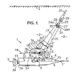
Referring to Figs. 1 to 4, in a first embodiment of the present invention, a
marine
anchor 1 for deep embedment in operation in a soil 2 below a seabed surface 3
comprises two flukes 4 joined together at a junction 5 in a plane of symmetry
6 of anchor
1 and together attached rigidly along junction 5 to a plate shank 7 located in
plane of
symmetry 6. Plane of symmetry 6 is shown as a vertical dashed line in Figs. 3
and 4
and a horizontal dashed line in Fig. 2. Each fluke 4 has a planar upper
surface 8.
Upper surfaces 8 are inclined relative to each other to include an anhedral
angle E
(Fig.3) having a magnitude in the range 120 to 180 with 140 preferred. The
centroid
9 (Fig. 1) of combined surfaces 8 lies in plane of symmetry 6. A reference
straight
line-10 containing centroid 9 and lying parallel to planar upper surfaces 8
defines a
forward direction F and a rearward direction R of anchor 1. Each fluke 4 has a
generally pentagonal shape in plan view (Fig. 2) with a forward point 11
spaced from
plane of symmetry 6. Plate shank 7 includes an elongated slot 12 having a
first load
application point 13 at a forward end 14 and a second load application point
15 at a
rearward end 16 of slot 12. The distance separating each of first load
application point
13 and second load application point 15 from centroid 9 is in the range 0.12IA
to 0.4IA
CA 02796276 2012-10-12
WO 2011/128689 PCT/GB2011/050736
9
with the range 0.15JA to 0.25IA preferred where A denotes the combined plan
area of
flukes 4 as shown in Fig. 2. The distance separating first load application
point 13 from
second load application point 15 is in the range of 0.03IA to 0.3IA. A
straight line 17
containing centroid 9 and first load application point 13 forms a forward-
opening acute
centroid angle A with reference straight line 10. Similarly, a straight line
18 containing
centroid 9 and second load application point 15 forms a rearward-opening acute
centroid
angle C with reference straight line 10. The magnitude of each of centroid
angle A and
centroid angle C is in the range 68 to 82 , with 75 further preferred. It is
preferred but
not essential that centroid angle C is equal to centroid angle A. Axis 19 of
slot 12
contains first load application point 13 and second load application point 15
and lies at a
forward-opening angle G relative to reference straight line 10. The magnitude
of
forward-opening angle G is chosen to be in the range 5 negative to 15
positive with 0
preferred, where first load application point 13 is nearer to reference
straight line 10 than
second load application point 15 when angle G is negative.
Anchor 1 includes an elongate auxiliary shank 20 which has a clevis 21
including a
pin hole 22 at a lower end 23 and a shackle lug hole 24 at an upper end 25.
The
distance between pin hole 22 and shackle lug hole 24 is in the range 0.7IA to
IA, with
0.85IA preferred. Clevis 21 straddles shank 7 and is attached thereto by a
load pin 26
located in pin hole 22 and passing through slot 12. The diameter of load pin
26 is
slightly smaller than the width of slot 12 so that load pin 26 can slide
freely from first load
application point 13 to second load application point 15 when a component of
load in
direction F in anchor line 30 is reversed to cause auxiliary shank 20 to
rotate
anticlockwise about load pin 26 (Fig. 1) and move rearwards in direction R.
For clarity,
Fig.1 shows clevis 21 partially sectioned to show the first load application
point 13 in
shank 7 at the forward end 14 of slot 12.
Pin 27 of shackle 28 is fitted in shackle lug hole 24, which has a centre 24A,
to
connect auxiliary shank 20 via shackle 28 and socket 29 to anchor line 30.
Clevis 21
includes a shear pin hole 31 positioned to be alignable with one of a
plurality of shear pin
holes 32 in shank 7 for receiving shear pin 33. When shear pin 33 is located
in shear
pin hole 31 and in one of shear pin holes 32, load pin 26 is located at first
load
application point 13 and auxiliary shank 20 is held such that a straight line
34 containing
the centre 24A and centroid 9 forms a preliminary forward-opening acute
centroid angle
R relative to reference straight line 10. The magnitude of preliminary forward-
opening
centroid angle R is chosen to be in the range 52 to 68 with 60 preferred
for operation
in soft clay soils. The plurality of shear pin holes in shank 7 permits step-
wise selection
of the magnitude of angle R by locating shear pin 33 in a particular shear pin
hole in
CA 02796276 2012-10-12
WO 2011/128689 PCT/GB2011/050736
shank 7. When auxiliary shank 20 is thus constrained by shear pin 33, centre
24A of
shackle lug hole 24 is held at a preliminary load application point 35,
defining preliminary
forward-opening centroid angle R relative to flukes 4 of anchor 1, which
facilitates
complete penetration of anchor 1 through seabed surface 3 and along an
inclined sub-
5 surface trajectory constrained by centroid angle R to reach a depth of
penetration of
centroid 9 below seabed surface 3 of about 2IA. This is sufficiently deep to
allow shear
pin 33 to be parted safely, by increasing the inclination of anchor line 30
while under
tension, to free auxiliary shank 20 to rotate about load pin 26 and so
transfer the loading
applied to anchor 1 from preliminary load application point 35 to first load
application
10 point 14 to enable subsequent burying along a more steeply inclined
trajectory
constrained by larger forward-opening acute centroid angle A.
A deflector plate 36 (Figs. 1, 2, and 4) is located at a rear edge 37 of fluke
4 and has
a planar upper surface 38 which forms an inclined extension of fluke surface
8. A
straight line 39 parallel to plane of symmetry 6 and lying in surface 38 forms
a rearward-
opening angle D with reference line 10 when projected onto plane of symmetry
6. The
magnitude of angle D is in the range 10 to 40 with 30 preferred. The ratio
of the total
area of deflector plate upper surfaces 38 to the total area of fluke surfaces
8 is in the
range 0.02 to 0.2 with 0.09 preferred.
In a modification of anchor 1 (Figs. 1 to 4), flukes 4 are hingedly instead of
rigidly
attached to shank 7 by hinge 5A (not shown). Hinge 5A is located between
junction 5
and shank 7 with the axis 5B of hinge 5A lying in plane of symmetry 6 and
parallel to
reference straight line 10 to permit shank 7 to be rotated out of plane of
symmetry 6 to
permit anchor 1 to resist loading out of the plane of symmetry 6 as the
azimuthal
direction of anchor line 30 changes.
Referring to Figs. 5 to 10, in a second embodiment of the present invention, a
marine
anchor 40 for deep embedment in operation in a soil 2 below a seabed surface 3
comprises a fluke 41 formed by a central plate 42 with an upper surface 42A
and two
inclined side plates 43 each with an upper surface 43A and each joined to
central plate
42 at junctions 44. Junctions 44 are parallel to and spaced from a plane of
symmetry
45 (Figs. 7, 8, and 9) of anchor 40. Plate stiffening ribs 44A (Figs. 5 to 9)
are attached
to an underside of fluke 41 along the length of each of junctions 44. Side
plates 43 are
inclined relative to each other to include an anhedral angle E below fluke 41
(Figs. 7 and
8) of magnitude in the range 180 to 120 with 140 preferred. Centroid 46
(Fig. 9) of
the combined upper surfaces 42A and 43A of plates 42 and 43 lies in the plane
of
symmetry 45. Reference straight line 47 (Figs. 5, 6, and 9) containing
centroid 46 and
lying parallel to upper surface 42A of central plate 42 defines forward
direction F and
CA 02796276 2012-10-12
WO 2011/128689 PCT/GB2011/050736
11
rearward direction R of anchor 40. At each side of plane of symmetry 45, each
half of
fluke 41 has a generally pentagonal shape in plan view with a forward point 48
spaced
from plane of symmetry 45. A deflector plate 76 (Figs. 5, 6, and 9) is located
at a rear
edge 77 of central plate 42 of fluke 41 and has a planar upper surface 78
(Fig. 9) which
forms an inclined extension of upper surface 42A of central plate 42. A
straight line 79
(Fig. 5) parallel to plane of symmetry 45 and located in surface 78 forms a
rearward-
opening angle D with reference line 47 measured in plane of symmetry 45. The
magnitude of angle D is in the range 10 to 40 with 30 preferred. The ratio
of the area
of deflector plate upper surface 78 to the total plan area of surfaces 42A and
43A is in
the range 0.02 to 0.2 with 0.09 preferred.
Shank 49 of anchor 40 includes a coupling plate 50 (Figs. 5 and 6) and two
forward
cables 51 F and two rearward cables 52R. Shank 49 is attached to a forward lug
53F
and to a rearward lug 53R on each of stiffening ribs 44A of fluke 41. Lugs 53F
and 53R
have centres 53A and 53B respectively and protrude through upper surfaces 42A
and
43A of fluke 41. Lugs 53F and 53R are equally spaced from centroid 46 (Fig.
9). Each
of cables 51 F and 52R is terminated by a socket 54L at each lower end and by
a socket
54U at each upper end. Each of sockets 54L has a shackle 55 linked there-
through as a
means of attaching each forward cable 51 F to each corresponding forward lug
53F and
each rearward cable 52R to each corresponding rearward lug 53R. Forward pair
of
cables 51 F is attached to coupling plate 50 at a forward lug hole 57F with
centre 57A by
a shackle 56 linking through two sockets 54U (Figs. 5, 6, and 7). Similarly,
rearward
pair of cables 52R is attached to coupling plate 50 at a rearward lug hole 57R
with
centre 57B by a shackle 56 linking through two sockets 54U (Figs. 5, 6, and
8).
Referring now to Fig. 10, for inclusion in anchor 40, a coupling plate 50 is
generally
of quadrilateral shape in side view with upper edge 58 lying parallel to lower
edge 59
separated by forward edge 60 and rearward edge 61. An elongated slot 62 is
located
above forward lug hole 57F and rearward lug hole 57R in coupling plate 50 and
has
therein a first load application point 63 at forward end 64 of slot 62 and a
second load
application point 65 at rearward end 66 of slot 62. Slot 62 serves to receive
pin 67 of
shackle 68 (Fig. 5) which is provided for linking through terminal socket 69
of anchor line
70. Slot 62 is slightly greater in width than the diameter of pin 67 of
shackle 68 whereby
pin 67 may slide from first load application point 63 at forward end 64 of
slot 62 to
second load application point 65 at rearward end 66 of slot 62. Distance L
(Fig. 10)
between first load application point 63 and second load application point 65
of coupling
plate 50 is preferred to be less than distance M separating centres 57A and
57B of lug
holes 57F and 57R respectively in coupling plate 50. Distance L plus the
diameter of
CA 02796276 2012-10-12
WO 2011/128689 PCT/GB2011/050736
12
pin 67 equals the overall length of slot 62. Ratio M/L is preferably in the
range of 1 to 3
with the range 1.5 to 2.5 further preferred. Lug holes 57F and 57R are
preferably but
not necessarily symmetrically disposed about a straight line 72 in the plane
of coupling
plate 50 which bisects at right angles a straight line 73 containing first
load application
point 63 and second load application point 65. A straight line 73A contains
centres 57A
and 57B of lug holes 57F and 57R respectively and lies parallel to straight
line 73.
Distance N between straight line 73 and straight line 73A is preferably in the
range of
zero to 0.5 times distance M with the range zero to 0.3 times distance M
further
preferred, although values of N outside of this range may be used. Coupling 50
enables a bi-stable mechanism 49B to be realized in anchor 40 as hereinafter
described.
In anchor 40, when pin 67 of shackle 68 is lodged at first load application
point 63
and cables 51 F and 52R are taut, first load application point 63 is held at
first stable
point 74 and a straight line 74A containing first stable point 74 and centroid
46 forms a
forward-opening acute angle A with reference straight line 47 (Fig. 5).
Likewise, when
pin 67 is lodged at second load application point 65 and cables 51 F and 52R
are taut,
first load application point 65 is held at second stable point 75 and a
straight line 75A
containing second stable point 75 and centroid 46 forms a rearward-opening
acute angle
C with reference straight line 47 (Fig. 6). The magnitudes of distances L, M,
and N of
coupling plate 50 (Fig. 10) may be chosen together with distances P and Q of
shank 49
(Fig. 6) to obtain any practical desired value for angle A or angle C.
Distance P is the
distance, measured in plane of symmetry 45 (Figs. 7, 8 and 9), between centre
57A of
forward lug hole 57F in coupling plate 50 and the intersection with plane of
symmetry 45
of a straight line joining centres 53A of forward lugs 53F on fluke 41.
Distance Q is the
distance, measured in plane of symmetry 45, between centre 57B of rearward lug
hole
57R in coupling plate 50 and the intersection with plane of symmetry 45 of a
straight line
joining centres 53B of rearward lugs 53R on fluke 41. Distances P and Q are
such that
coupling plate 50 is maintained clear of fluke 41 when anchor 40 is subjected
to loading
by anchor line 70.
When a forward-directed component of force is applied to anchor 40 when buried
in
soil 2, by tensioning anchor line 70, pin 67 of shackle 68 lodges at first
load application
point 63 and so tensions cables 51 F and cables 52R. In consequence, shank 49
including cables 51F, cables 52R, and coupling plate 50 rotate to bring first
load
application point 63 into first stable position 74 relative to fluke 41 when
force equilibrium
is established. Straight line 74A (Fig. 5), containing first stable position
74 and centroid
46, is now collinear with axis 70A of anchor line 70 and forms forward-opening
angle A
with reference straight line 47, in the range 68 to 82 with 75 preferred.
The
CA 02796276 2012-10-12
WO 2011/128689 PCT/GB2011/050736
13
separation between first stable position 74 and centroid 46 is chosen to be in
the range
0.5IA to 1.7IA with the range 0.8IA to 1.2IA preferred. Pin 67 is stable when
held at
first stable position 74, while lodged at first load application point 63, in
that the
inclination to the horizontal of axis 70A of anchor line 70 at shackle 68 can
be changed
progressively from being almost parallel to a plane containing cables 51 F to
being
almost parallel to a plane containing cables 52R without dislodging pin 67 of
shackle 68
from first load application point 63 or completely losing tension in either of
cables 51 F or
cables 52R. Thus, the inclination of axis 70A of anchor line 70 can be varied,
for
example, by about plus or minus 15 without causing pin 67 of shackle 68 to
slide in slot
62 of coupling plate 50 away from first load application point 63.
When anchor line 70 is now pulled such as to introduce a rearward component of
force on anchor 40 via pin 67 of shackle 68, lodged at first load application
point 63 and
presently held at first stable position 74 (Fig. 5), shank 49 including cables
51 F and
cables 52R rotate anticlockwise rearward (Fig. 6) under tension while coupling
plate 50
rotates clockwise such that pin 67 of shackle 68 slides in slot 62 from first
load
application point 63 to second load application point 65. When force
equilibrium is re-
established, second load application point 65 is held in second stable
position 75 (Fig. 6)
relative to fluke 41 while the rearward-directed component of tension is
maintained.
Straight line 75A, containing second stable position 75, axis 70A (Fig. 6) of
anchor line
70, and centroid 46, forms rearward-opening angle C with reference straight
line 47, in
the range 68 to 82 with 75 preferred. The separation between second stable
position
75 and centroid 46 is chosen to be in the range 0.5IA to 1.65IA with the range
0.9IA to
1.3JA preferred where A denotes the plan area of fluke 41 as shown in Fig. 6.
Pin 67 is
stable when held at second stable position 75, while lodged at second load
application
point 65, in that the inclination to the horizontal of axis 70A of anchor line
70 at shackle
68 can be changed progressively from being almost parallel to a plane
containing cables
52R to being almost parallel to a plane containing cables 51 F without
dislodging pin 67
from second load application point 65 or completely losing tension in either
of cables
52R or cables 51 F. The inclination of axis 70A of anchor line 70 can be
varied, for
example, by about plus or minus 15 without causing pin 67 to slide in slot 62
of coupling
plate 50 away from second load application point 65.
It is notable that when cables 51F and 52R rotate anti-clockwise under
tension,
coupling plate 50 rotates clockwise. This progressively changes the
inclination to
horizontal of slot 62 and so precipitates sliding therein of pin 67 of shackle
68 from first
load application point 63 to second load application point 65 of coupling
plate 50 and,
hence, when force equilibrium is established, from first stable position 74 to
second
CA 02796276 2012-10-12
WO 2011/128689 PCT/GB2011/050736
14
stable position 75, driven by tension in anchor line 70. The arrangement of
anchor 40
comprising fluke 41 and shank 49 including cables 51 F, cables 52R, and
coupling plate
50, together with shackle 68, thus constitutes a bi-stable mechanism 49B
wherein an
appropriate and sufficient change of the inclination of axis 70A of anchor
line 70
attached to shackle 68 can trigger, or switch, the bi-stable mechanism 49B
from a first to
a second stable geometrical configuration including forward-opening acute
angle A and
rearward-opening acute angle C respectively and vice versa.
Referring to Figs. 11 to 13, marine anchor 40 is fitted with a distance
adjuster 80
(Figs. 11 and 12) for altering temporarily distance P to provide a forward-
opening acute
angle R which is smaller than forward-opening acute angle A. Angle R is in the
range of
54 to 66 , with 60 preferred. Angle R is provided to facilitate penetration
of fluke 41
through seabed surface 3 into a soft soil 2. Distance adjuster 80 is connected
between
forward lug hole 57F on coupling plate 50 and shackle 56 linking with sockets
54U which
terminate appropriately shortened forward cables 51 F. Distance adjuster 80
comprises
two parallel identical elongated plates 81 fixed together and spaced
sufficiently apart by
a spacing plate 82 to be able to straddle coupling plate 50. At a forward end
83 of
plates 81 is a hole 84 having a diameter equal to that of forward lug hole 57F
in coupling
plate 50. Pin 85 is located through holes 84 and 57F to attach distance
adjuster 80 to
coupling plate 50 instead of shackle 56. Plates 81 have lugs 86 containing
shear pin
hole 87 located towards hole 84 on the opposite side of plates 81 from spacing
plate 82.
An elongated plate 88 is located between plates 81 and is hingedly attached at
a
rearward end 89 of plate 88 to a rearward end 90 of plates 81 by pin 91. A
hole 92 with
centre 92A is provided at a forward end 93 of plate 88 for the attachment of
shackle 56
linking with sockets 54U which terminate cables 51 F. Plate 88 can swing
between
plates 81 to bring a shear pin hole 94 in plate 88 into alignment with shear
pin hole 87 in
plates 81 whereby a shear pin 95 may be fitted in the aligned holes. When
shear pin 95
parts, plates 81 and 88 are free to rotate into axial alignment (Fig. 12) and
thus increase
separation distance P - (S - T) (Fig. 11) between centre 57A of lug hole 57F
and centre
53A of lug 53F by distance S minus T. S is the maximum distance possible (Fig.
12)
between centre 57A of hole 57F and centre 92A of hole 92 when shear pin 95 is
omitted
or parted. Distance T (Fig. 11) is the minimum distance separating centre 57A
of hole
57F and centre 92A of hole 92, measured parallel to cable 51 F, when shear pin
95 is
fitted and is intact. When shear pin 95 is fitted between plates 81 and 86 of
distance
adjuster 80 of anchor 40, distance P is shortened by distance (S - T). When a
forward-
directed component of force is applied at first load application point 63,
first load
application point 63 is now held at a preliminary stable position 96 relative
to fluke 41
CA 02796276 2012-10-12
WO 2011/128689 PCT/GB2011/050736
(Fig. 11). A straight line 96A containing preliminary stable position 96 and
centroid 46
forms acute forward-opening angle R with reference straight line 47. The
magnitude of
angle R is determined by selecting appropriate magnitudes for distances S and
T (Figs.
11 and 12) and, as mentioned previously, is in the range of 54 to 66 with
60 preferred
5 for soft soils.
When anchor 40 is laid on seabed surface 3 and pulled horizontally thereon by
anchor line 70 with pin 67 of shackle 68 located at first load application
point 63 of
coupling plate 50, penetration of fluke 41 through seabed surface 3 into soil
2 is
facilitated by the presence of forward-opening acute angle R maintained by
shear pin 95
10 in closed distance adjuster 80 (Fig. 11). When centroid 46 of fluke 41 is
at a certain
depth below seabed surface 3 exceeding 2'A, soil loading on fluke 41 causes
shear pin
95 to part. Consequently, distance adjuster 80 opens to allow shank 49 to
rotate and so
move pin 67 from preliminary stable position 96 to first stable position 74
which defines
forward-opening acute angle A (Fig. 12). As before, angle A is in the range of
68 to
15 82 with 75 preferred. As previously mentioned, the separation between
first stable
position 74 and centroid 46 is chosen to be in the range 0.5IA to 1.65IA with
the range
0.9IA to 1.3IA preferred. When the direction of anchor line 70 is now altered
and
tensioned to apply a rearward-directed component of force at first load
application point
63 held at first stable position 74, cables 51 F together with opened distance
adjuster 80
and cables 52R rotate anticlockwise rearward under tension and coupling plate
50
rotates clockwise such that pin 67 of shackle 68 slides in slot 62, driven by
tension in
anchor line 70, from first load application point 63 to second load
application point 65.
The second load application point 65 arrives at and is held at second stable
position 75
(Fig. 13) relative to fluke 41 while the rearward-directed component of force
is
maintained. A straight line 75A containing second stable position 75 and
centroid 46, is
collinear with axis 70A of anchor line 70 and forms a rearward-opening acute
angle C
with reference straight line 47, in the range of 68 to 82 , with 75
preferred. As
previously mentioned, the separation between second stable position 75 and
centroid 46
is chosen to be in the range 0.5IA to 1.65IA with range 0.9IA to 1.3IA
preferred. As
before, the arrangement of shank 49 (now including opened distance adjuster
80, cables
51 F, cables 52R, and coupling plate 50), shackle 68, and fluke 41 constitutes
a bi-stable
mechanism 49B.
Referring to Figs. 14 and 15, if the rearward- burying near normal load mode
of
operation is not required, for example, in regions where hurricanes do not
occur, anchor
40A includes coupling plate 50 and cables 52R, as in anchor 40 (Figs. 5 and
6), but has
cables 51 F reduced in length to make distance P about 0.75 times distance Q
instead of
CA 02796276 2012-10-12
WO 2011/128689 PCT/GB2011/050736
16
being equal to distance Q. When pin 67 of shackle 68 is loaded and lodged at
first load
application point 63 in coupling plate 50, first load application point 63
stabilizes at
preliminary stable point 96 as previously described for anchor 40 (Fig. 11).
Preliminary
stable point 96 defines forward-opening acute angle R. Forward-opening acute
angle R
is in the range of 54 to 66 with 60 preferred and, as before, is
provided to facilitate
seabed surface penetration by fluke 41 in soft soils. Distances L, M, and N in
coupling
plate 50 are selected such that when pin 67 of shackle 68 is loaded and lodged
at
second load application point 65 of coupling plate 50, second load application
point 65
stabilizes at first stable point 74 as previously described for anchor 40
(Fig. 12). First
stable point 74 defines forward-opening acute angle A which, as before, in the
range of
68 to 82 , with 75 preferred. Anchor 40A thus includes the bi-stable
mechanism 49B
previously described. When anchor 40A is embedded in soil 2 with pin 67 of
shackle 68
held at first stable position 96 for installation, with anchor line 70
inclined to horizontal at
seabed surface 3 by up to 25 , and with fluke centroid 46 below seabed surface
3 by
more than 2IA, the bi-stable mechanism 49B may be triggered by increasing the
inclination of anchor line 70 to horizontal at seabed surface 3 into the range
of 40 to 60
while under tension. This, in turn, increases the inclination of anchor line
70 at shackle
68 and causes shank 69, including cables 51 F and 52R and coupling plate 50,
to rotate
under tension in soil 2. However, as mentioned previously, coupling plate 50
rotates in
the opposite sense to the rotation of cables 51 F and 52R of shank 49. In
consequence,
the slope of slot 62 in coupling plate 50 changes progressively to a point
where pin 67 of
shackle 68 slides from first load application point 63 to second load
application point 65
whereby forward-opening acute angle R increases to become forward-opening
acute
angle A and pin 67 of shackle 68 is held at second stable position 74 (Fig.
15). When
anchor line 70 is now pulled at a reduced operational inclination angle at
seabed surface
3 typically in the range of 15 to 35 , anchor 40A buries along a steeper
trajectory in the
before-mentioned "near normal load mode" of anchor operation to provide
holding
capacity to match the loading in anchor cable 70 up to the point where anchor
cable 70
parts. It is noteworthy that, in this arrangement of anchor 40A, the near
normal load
mode of operation at forward-opening acute angle A, following surface
penetration and
initial burial at smaller forward-opening acute angle R, is achieved by simply
increasing
and then decreasing the angle of inclination of anchor line 70 at seabed
surface 3 while
under tension, without need for parting shear pin 95 in distance adjuster 80
as in the
arrangement of anchor 40 shown in Figs. 11 to 13, and without a need for an
auxiliary
line hitherto essential to enable a known alternative mechanism to be remotely
actuated.
This reduces mechanical complexity and increases operational versatility.
CA 02796276 2012-10-12
WO 2011/128689 PCT/GB2011/050736
17
Referring to Fig. 16, a modified coupling plate 50A, for inclusion in anchor
40A
mentioned hereinafter, differs from coupling plate 50 by having a slot 62A
which
incorporates an intermediate load application point 63A at a bend 62B therein
and by
being strengthened with increased material above slot 62A to resist bending
moment
arising when pin 67 of shackle 68 is lodged at and applies loading at
intermediate load
application point 63A. Intermediate load application point 63A is preferably
located
equidistant from first load application point 63 and second load application
point 65.
First load application point 63 and intermediate load application point 63A
lie on straight
line 62C while second load application point 65 and intermediate load
application point
63A lie on straight line 62D. A downward-opening obtuse angle F is included
between
straight lines 62C and 62D. Obtuse angle F is in a preferred range of 140 to
160 with
150 further preferred. It may be noted that if angle F is chosen to be
outside of the
preferred range and made equal to 180 , coupling plate 50A effectively becomes
identical to coupling plate 50. Coupling plate 50A enables a tri-stable
mechanism 49C
to be incorporated in anchor 40A.
Referring to Figs. 17 to 19, anchor 40B is a modification of anchor 40 (Figs.
5 and 6).
Anchor 40B includes a tri-stable mechanism 49C by virtue of substituting
coupling plate
50A (Fig. 16) for coupling plate 50 (Figs. 5, 6 and 10). Distance P is equal
to distance
Q (Fig. 18). Intermediate load application point 63A, in coupling plate 50A,
allows
utilization of an intermediate stable position 74B (Fig. 18) in anchor 40B,
between first
stable position 74 (for first load application point 63) and second stable
position 75 (for
second load application point 65), such that straight line 74C containing
intermediate
stable position 74B and centroid 46 forms an angle B with reference straight
line 47.
Angle B is a right angle when cables 51 F and 52R are of equal length where
distance P
equals distance Q. When loading from pin 67 of shackle 68 is applied at
intermediate
load application point 63A, point 63A stabilizes at intermediate stable
position 74B. This
permits anchor 40B to function additionally as a vertical load anchor, capable
of
providing the ultimate in holding capacity when resisting loads applied at
right angles to
fluke 41 (in what is known as the "vertical load mode" or "normal load mode"
of anchor
operation), as well as to function in the "near normal load mode" conferred by
the use of
angles A or C in the ranges mentioned previously wherein almost the full
capacity of the
vertical load mode is realizable while preserving the ability of anchor 40B to
continue
burying deeper below seabed surface 3 in forward or rearward directions. In a
manner
similar to that of the bi-stable mechanism 49B described previously, the tri-
stable
mechanism 49C may be triggered from first to second to third stable
geometrical
configuration of anchor 40B, encompassing forward-opening acute angle A,
intermediate
CA 02796276 2012-10-12
WO 2011/128689 PCT/GB2011/050736
18
angle B, and rearward-opening acute angle C respectively, and vice versa, by
appropriately and sufficiently changing the inclination of axis 70A of anchor
line 70
controlled by an installation vessel.
Referring to Figs. 20 to 22, anchor 40C is a version of anchor 40B modified
further to
include a tri-stable mechanism 49C having three forward-opening acute angles
a, R, and
A obtained by choosing distance P to be about 0.75 times distance Q instead of
being
equal to distance Q as shown in Fig. 18. In anchor 40C, pin 67 of shackle 68
first
lodges at first load application point 63 in coupling plate 50A which
stabilizes at first
initial stable position 97 defining forward-opening acute angle a (Fig. 20).
Pin 67 next
lodges at intermediate load application point 63A in coupling plate 50A which
stabilizes
at second initial stable position 96 defining forward-opening acute angle R
(Fig. 21).
Finally, pin 67 lodges at second load application point 65 in coupling plate
50A which
stabilizes at first stable position 74 defining forward-opening acute angle A
(Fig. 22).
Angle a is in the range of 35 to 50 , with 42 preferred, for facilitating
penetration
through seabed surface 3 into a firm soil 2. As before: angle R is in the
range of 54 to
66 , with 60 preferred, for facilitating penetration through seabed surface 3
into a soft
soil 2; and angle A is in the range of 68 to 82 , with 75 preferred, to
provide anchor
40C with near normal load mode capability when centroid 46 of fluke 41 is
buried at a
depth below seabed surface 3 exceeding 2IA. Again, the tri-stable mechanism
49C of
anchor 40C may be triggered from one stable position to another by increasing
and then
decreasing the inclination to horizontal at seabed surface 3 of anchor line 70
while under
tension. The advantages of arranging tri-stable anchor 40C to have three
forward-
opening acute angles includes: the capability of successful deployment in firm
as well as
in soft bottom soils without requiring prior adjustment of the geometry of
anchor 40; no
requirement for using shear pins; reduced mechanical complexity; and greatly
increased
operational versatility.
Distance adjuster 80 (Figs. 11 to 12) may be incorporated into anchor 40B
(Figs. 17
to 19) or into anchor 40C (Figs. 20 to 22) to realise four separate centroid
angles instead
of three by suitably choosing distances P and Q. Thus,
anchors 40B and 40C thus modified may have any four centroid angles chosen
from a,
R, A, B, and C to suit particular operational requirements.
For drag embedment installation of an anchor according to the first embodiment
of
the present invention as shown in Figs. 1 to 4, anchor 1 has auxiliary shank
20 initially
locked rotationally by shear pin 33 and then is lowered from an installation
vessel onto
seabed surface 3 so that fluke 4 rests thereon with reference straight line 10
horizontal.
Anchor line 30 is laid out on seabed surface 3 with sufficient length to
remain
CA 02796276 2012-10-12
WO 2011/128689 PCT/GB2011/050736
19
substantially horizontal near anchor 40 while tension is applied therein by
the installation
vessel to cause anchor 1 to tip forward until points 11 of flukes 4 penetrate
through
seabed surface 3 and shackle 28 makes contact there-with. In consequence of a
relatively small angle R maintained by shear pin 33, further tensioning causes
anchor 1
to penetrate through and then bury wholly below seabed surface 3 to follow a
curved
burial trajectory in soil 2. A progressively increasing soil reaction force is
impressed on
fluke 4 as the depth of burial of centroid 9 of fluke 4 increases. A
correspondingly
increasing moment-induced force is impressed on shear pin 33 due to the moment
about
load pin 26 of force in anchor line 30 acting along straight line 34
containing preliminary
load application point 35 and fluke centroid 9. Shear pin 33 parts when the
moment-
induced force exceeds the strength of shear pin 33. Auxiliary shank 20 is then
free to
pivot about load pin 26 which is lodged at first load application point 13 in
slot 12 of fluke
4. Thus, the load applied to anchor 1 is transferred from preliminary load
application
point 35 to first load application point 13. With loading now being applied at
the larger
forward-opening acute angle A, anchor 1 commences to bury along a steeper
trajectory
in the before-mentioned near normal load mode of anchor operation wherein much
deeper penetration below seabed surface 3 can occur to obtain greatly
increased
holding capacity. Installation is complete when shear pin 33 has parted and a
consequently increased resistance to pulling has allowed a prescribed anchor
line
tension to be held for 15 to 20 minutes.
For direct embedment installation of anchor 1, auxiliary shank 20 is first
removed and
pin 28A of shackle 28, linked through socket 29 of anchor line 30, is fitted
in slot 12 of
shank 7 instead of load pin 26 of shank 20. Anchor 1 is pushed vertically into
soil 2 as
described in US Patent 6598555 using a heavy elongate pile known as a follower
which
is pivotably and releasably attached to anchor 1. When anchor 1 has been
rotated
about 45 by reaction against the weight of the follower as the installation
vessel
cyclically heaves up and pays out anchor line 30 about five times, the
elongate follower
is removed from anchor 1. Installation is completed by the installation vessel
pulling
horizontally on anchor line 30 to hold a prescribed test tension for 15 to 30
minutes.
Subsequent overloading of anchor line 30 causes anchor 1 to move in forward
direction
F and follow a steeper near normal load trajectory as described previously
whereby
anchor 1 can provide holding capacity to match loading in anchor line 30 up to
the point
where anchor line 30 parts.
In hurricane conditions, when either drag-embedded or direct-embedded anchor 1
is
subjected to over loading with a substantial component of load being out of
plane of
symmetry 6, anchor 1 will veer in soil 2 assisted by anhedral angle E of
flukes 4 to bring
CA 02796276 2012-10-12
WO 2011/128689 PCT/GB2011/050736
plane of symmetry 6 into the direction of loading while burying deeper to
produce holding
capacity to match hurricane loading in anchor line 30 up to the point where
anchor line
parts. However, when anchor line 30 remains in plane of symmetry 6 and is
pulled
rearward over anchor 1, either load pin 26 of auxiliary shank 20 or pin 28A of
shackle 28
5 is pulled rearward and slides in slot 12 to lodge at second load application
point 15 and
so pulls anchor 1 rearward. Anchor 1 simultaneously rotates in soil 2 in plane
of
symmetry 6 due to the presence of a moment arm comprising distance H
separating
second load application point 15 from centroid 9 of flukes 4. Rotation is
assisted by soil
forces on deflector plates 36. Continued pulling causes anchor 1 to commence
burying
10 deeper in rearward direction R in the near normal load mode of operation to
produce
holding capacity to match hurricane loading in anchor line 30 up to the point
where
anchor line 30 parts. Thus, when deployed at multiple locations around an
offshore
exploration or production platform, anchor 1 is capable of providing holding
capacity in
any azimuthal direction of loading sufficient to part attached anchor line 30
so that
15 dragging of anchor 1 into a nearby pipeline does not occur.
When anchor 1 has not been pulled rearward in hurricane conditions, anchor 1
may
be recovered in the azimuthal direction of the installed anchor line 30 simply
by heaving
up on anchor line 30 at an inclination at seabed surface 3 in the range 60 to
80 and
maintaining tension in anchor line 30 by pulling horizontally thereon with a
recovery
20 vessel until anchor 1 moves along an upward-inclined path back to seabed
surface 3.
When anchor 1 has been pulled rearward, this recovery procedure is carried out
in the
opposite azimuthal direction.
For drag embedment installation of an anchor according to the second
embodiment
of the present invention as shown in Figs. 5 to 9 and 11 to 13, anchor 40 is
equipped
25 with distance adjuster 80 in which shear pin 95 is fitted (Fig. 11). Anchor
40 is lowered
from an installation vessel onto seabed surface 3 by means of anchor line 70
so that
fluke 41 comes to rest thereon with reference straight line 47 horizontal. The
installation vessel then moves slowly forward at a speed of about one knot
while paying
out anchor line 70 at the same speed. This lays anchor line 70 without tension
on
30 seabed surface 3. The installation vessel then stops both moving forward
and paying
out anchor line 70 when the length of anchor line 70 outboard is calculated to
provide an
angle of inclination of anchor line 70 at seabed surface 3 of between 15 and
25 to
horizontal at final installation tension. This minimises installation time in
deep water.
On commencing installation pulling, anchor line 70 adjacent to anchor 40 lies
horizontally
on seabed surface 3. Tension in anchor line 70 causes pin 67 of shackle 68 to
slide in
slot 62 of coupling plate 50 to lodge at first load application point 63
therein. This, in
CA 02796276 2012-10-12
WO 2011/128689 PCT/GB2011/050736
21
turn, exerts a forward-directed force via rear cables 52R on rear lugs 53B of
fluke 41
while forward cables 51 F remain slack. The line of action of force in rear
cables 52R
applied to upstanding lugs 53B has a small moment about centroid 46 which,
together
with soil resistance at fluke points 48, causes fluke 41 to tip up and
penetrate through
seabed surface 3 at a small angle of inclination to horizontal. As penetration
progresses, fluke 41 tips up further until cables 51 F become taut as well as
cables 52R
and first load application point 63 is held at preliminary stable position 96
which defines
preliminary forward-opening acute centroid angle R which is smaller than
forward-
opening acute centroid angle A (Fig. 11). Angle R, being relatively small,
prevents
anchor 40 from pulling out of soil 2 while fluke 41 is in close proximity to
seabed surface
3 by failing a wedge of soil above fluke 41. Further pulling on anchor line 70
causes
anchor 40 to penetrate deeper along an inclined path below seabed surface 3.
At a
certain depth of penetration of fluke centroid 46 below seabed surface 3, soil
reaction
load on fluke 41 induces sufficient tension in cables 51 F to part shear pin
95 in distance
adjuster 80 to allow elongated plates 81 and 88 to swing into alignment with
each other
and to cause distance P - (S - T) to increase to P and cause shank 49 to
rotate relative
to fluke 41 to move first load application point 63 from preliminary stable
position 96 to
first stable position 74 which defines larger forward-opening acute centroid
angle A
(Figs. 11 and 12). The parting strength of shear pin 95 is chosen to allow
centroid 46 of
fluke 41 to reach a depth below seabed surface 3 exceeding 2'A before shear
pin 95
parts, where A is the total area of plates 42 and 43 plus the area of
deflector plate 76
seen in plan view (Fig. 9). Further pulling causes anchor 40 to follow a
steeper near
normal load trajectory as described previously. When a prescribed installation
tension
is reached, the scope of anchor line 70 is adjusted to bring anchor line 70 to
an
operational angle of inclination to horizontal at seabed surface 3 of
typically between 15
and 35 . The prescribed installation tension is then maintained for 15 to 30
minutes by
way of final testing of the installation prior to connecting to a structure to
be moored.
In hurricane conditions, when drag-embedded anchor 40 is deeply embedded in
the
near normal load mode and subjected to overloading with a substantial
component of
load out of plane of symmetry 45, anchor 40 will veer in soil 2, assisted by
anhedral
angle E of fluke plates 43, to bring plane of symmetry 45 into the direction
of loading
while burying deeper to provide holding capacity to match hurricane loading in
anchor
line 70 up to the point where anchor line 70 parts.
However, when anchor line 70 remains in plane of symmetry 45 and is pulled
rearward over anchor 40, the inclination to horizontal of the loading
direction at shackle
68 increases and triggers the bi-stable mechanical system of anchor 40, as
hereinbefore
CA 02796276 2012-10-12
WO 2011/128689 PCT/GB2011/050736
22
described, whereby shank 49 automatically reconfigures geometrically such that
pin 67
of shackle 68 moves in slot 62 of coupling plate 50 to lodge at second load
application
point 65 which, in turn, moves to second stable position 75 (Fig. 13) to
establish
rearward-opening acute centroid angle C. Continued pulling causes anchor 40 to
rotate
and commence burying deeper in rearward direction R in the near normal load
mode of
operation to produce holding capacity to match hurricane loading in anchor
line 70 up to
the point where anchor line 70 parts. Thus, as for anchor 1, when deployed at
multiple
locations around an offshore exploration of production platform, anchor 40 is
capable of
providing holding capacity in any azimuthal direction of loading sufficient to
part anchor
line 70 so that dragging of anchor 40 into a pipeline does not occur.
If anchor 40 has not been pulled rearward in hurricane conditions, anchor 40
may be
recovered in the azimuthal direction of installation simply by heaving up on
anchor line
70 at an inclination to horizontal at seabed surface 3 in the range of 60 to
80 and
maintaining tension in anchor line 70 by pulling horizontally thereon with a
recovery
vessel until anchor 70 moves along an upward-inclined path back to seabed
surface 3.
If anchor 70 has been pulled rearward, this latter recovery procedure is
carried out in the
opposite azimuthal direction.
For drag embedment installation of an anchor according to a first modification
of the
second embodiment of the present invention as shown in Figs. 14 and 15, anchor
40A is
deployed on seabed surface 3 and embedded in soil 2 in the same manner as for
anchor
40, described previously, up to the point where shear pin 95 in distance
adjuster 80 of
anchor 40 would be about to part. At this point, tension in anchor line 70
measured at
the installation vessel reaches a prescribed value. Tension is then reduced to
allow
shortening of the scope of anchor line 70 such that, when tension is restored,
the angle
of inclination to horizontal at seabed surface 3 of anchor line 70 has been
increased by
some 20 to 30 . This increases the inclination of axis 70A of anchor line 70
at shackle
68 attached to embedded anchor 40A sufficiently to trigger the bi-stable
mechanism 49B
of anchor 40A to cause shank 49 to rotate relative to fluke 41 to move first
load
application point 63 from preliminary stable position 96 to first stable
position 74 which
defines larger forward-opening acute centroid angle A (Fig. 15). Tension in
anchor line
70 is then reduced again and the scope of anchor line 70 is increased to a
scope
calculated to produce an inclination to horizontal of anchor line 70 at seabed
surface 3 to
between 15 and 25 at final installation tension. Further pulling causes
anchor 40A to
follow a steeper near normal load trajectory as described previously. When the
final
installation tension is reached, the scope of anchor line 70 is recalculated
and adjusted
to bring anchor line 70 to an operational angle of inclination to horizontal
at seabed
CA 02796276 2012-10-12
WO 2011/128689 PCT/GB2011/050736
23
surface 3 of between 15 and 35 at a prescribed test tension. The prescribed
test
tension is then maintained for 15 to 30 minutes by way of final proving of the
installation
prior to connecting to a structure to be moored. Recovery of anchor 40A is
accomplished by using the same procedure as for anchor 40.
For drag embedment installation of an anchor according to a second
modification of
the second embodiment of the present invention as shown in Figs. 17 to 19,
anchor 40B
is fitted with distance adjuster 80 as for bi-stable anchor 40 shown in Figs.
11 to 13.
Thus fitted, anchor 40B is installed in the same manner as described for
anchor 40 and
also functions in hurricane conditions as described for anchor 40. However,
the
presence of intermediate stable position 63A in the tri-stable mechanism 49C
of anchor
40B provides an option to operate anchor 40B as a normal load anchor by
locating pin
67 of shackle 68 at intermediate load application point 63A in coupling plate
50B by
appropriate manipulation of the inclination to horizontal of anchor line 70 at
seabed
surface 3 as previously described. Anchor 40B can then be used in applications
requiring anchor line 70 to resist high loading when pulled vertically.
Recovery
procedure for anchor 40B is similar to that of anchor 40 with the exception
that, when
anchor 40B has been operated in the vertical load mode, anchor line 70 must
first be
paid out to establish long scope and then pulled to move pin 67 of shackle 68
from
intermediate load application point 63A to first load application point 63
before
commencing the recovery procedure.
For drag embedment installation of an anchor according to a third modification
of the
second embodiment of the present invention as shown in Figs. 20 to 22, the
procedure
used is the same as that for anchor 40A previously described with reference to
Figs. 14
and 15. Recovery procedure for anchor 40C is similar to that of anchor 40 with
the
exception that anchor line 70 must first be paid out to establish long scope
and then
pulled to move pin 67 of shackle 68 from second load application point 65 or
from
intermediate load application point 63A to first load application point 63 in
coupling plate
50A before commencing the recovery procedure.
Further modifications of the anchors herein described are, of course, possible
within
the scope of the present invention. For example, the magnitudes of the angles
a and R
in anchors 1 and 40, 40A, 40B and 40C may be chosen to be outside of the above-
noted
ranges for particular applications and elongate members 51 F and 52R may be
rigid
beams.