Note: Descriptions are shown in the official language in which they were submitted.
CA 02796614 2012-11-21
-1-
FUEL INJECTOR CALIBRATION AND TRIMMING
Field of the Invention
[0001] The present application relates to a technique of calibrating gaseous
fuel
injectors after assembly and trimming the same during operation in an internal
combustion engine.
Background of the Invention
[0002] Combustion control is an important factor in optimizing fuel economy
and
performance in internal combustion engines. The amount of fuel introduced to
the
combustion chamber and the timing when that fuel is introduced contributes to
the
quality of combustion at any given engine operating condition. Fuel injectors
are capable
of introducing specific amounts of fuel at a given time by way of an actuation
signal that
originates in an engine controller. However, fuel injectors are multi-part
mechanical
components with moving pieces that exhibit performance variations from part to
part, due
to design factors and dimensional variances, even when the fuel injectors are
made within
specified manufacturing tolerances. When fuel injectors are activated with a
nominal
actuation signal the amount of fuel injected and the timing of when that fuel
is introduced
can be different from one injector to another injector.
[0003] There are known techniques for correcting performance variations in
fuel
injectors. These techniques primarily address fuel injectors that introduce a
liquid fuel,
such as Diesel, to the combustion chamber. In a calibration phase during
manufacturing,
each fuel injector is actuated with a variety of actuation signals as a
function of liquid rail
pressure such that the actual quantity of fuel injected and other fuel
injector
characteristics can be measured and compared against set point values such
that
correction factors are identified. A bar code or other means on the fuel
injector stores the
CA 02796614 2012-11-21
-2-
correction factors, also known as trim information, such that when the fuel
injector is
installed in an engine the engine controller can be programmed with these
values.
[00041 In the case of hydraulically actuated fuel injectors that introduce
both a pilot
fuel and a gaseous fuel, separately and independently, the quantity of gaseous
fuel
introduced by the injector and its timing is a function of more than just
liquid rail
pressure. For example, both the pilot (liquid) fuel rail pressure and gaseous
fuel rail
pressure influence injector performance. In liquid fuel injection systems the
rail pressure
is significantly higher than cylinder pressure in order to atomize the fuel
during injection,
for example diesel common rail pressure can be in the range 1000 bar to 1800
bar, and
even higher. The differential pressure between in-cylinder pressure and liquid
rail
pressure is of a sufficiently large magnitude that the influence of in-
cylinder pressure
variations on injector performance is insignificant. However, when injecting a
gaseous
fuel directly into a combustion chamber, in-cylinder pressure variations can
influence
injector performance when gaseous fuel rail pressure is substantially less
than liquid fuel
rail pressure. There are a variety of reasons for designing a gaseous fuel
injector to
operate with a lower gaseous fuel rail pressure, for example between 100 bar
and 500 bar.
For instance, atomization is not required for a gaseous fuel so there is no
motivation to
increase gaseous rail pressure for this reason. Compressing a gaseous fuel, a
compressible substance, requires more energy than compressing a liquid fuel,
an
incompressible substance, so the desire to maximize engine efficiency favors
using a
lower gaseous fuel rail pressure, as long as the pressure is high enough to
inject the
demanded quantity of fuel at corresponding engine operating conditions, and
with this
objective in mind, people skilled in the design of fuel injectors can design
fuel injectors
with the needed flow capacity at lower pressures. As a result, for many
gaseous fuel
injectors, the differential between in-cylinder pressure and gaseous rail
pressure is of a
smaller magnitude, compared to typical liquid fuel injectors, with a
consequence of this
being that, for gaseous fuel injectors, in-cylinder pressure variations can be
a factor in
injector performance.
CA 02796614 2012-11-21
-3-
[0005] Other parameters influencing injector performance are hydraulic fluid
pressure and hydraulic pulse width. When activated by the nominal actuation
signal,
hydraulic fluid pressure decreases inside the injector actuating mechanisms to
inject fuel.
Because of the aforementioned dimensional variances that are inevitably
introduced
during manufacturing, the injectors exhibit performance variations caused by
changes in
hydraulic fluid pressure, such as closing and opening times. As the desired on-
time
(hydraulic pulse width) for the injector decreases the variations in opening
and closing
time of the injector have an increased influence on the amount of fuel that is
actually
introduced. This influence is especially noticeable when the injector
partially opens. The
fuel flow area in an opened injector changes from injector to injector because
of
dimensional differences introduced by the manufacturing process which allows
variations
within specified tolerances. Therefore for identical hydraulic pulse widths
(desired
injector on-time) the amount of fuel that is actually introduced can be
different from one
injector to another injector even though both are manufactured in accordance
with
specifications.
[0006] Unlike a simpler monofuel injector that injects only one fuel, there
are at least
four parameters that influence fuel injector performance in a hydraulically-
actuated
gaseous fuel injector introducing both a pilot fuel and a gaseous fuel,
separately and
independently. These parameters are pilot fuel (liquid) rail pressure, gaseous
fuel rail
pressure, in-cylinder pressure and hydraulic pulse width. During the
calibration phase
using traditional liquid fuel trimming techniques, an increased number of test
points are
required for the gaseous fuel injector described above, due to the number of
parameters
influencing injector performance, compared to a conventional liquid fuel
injector,
resulting in a larger amount of fuel injector trim information.
[0007] Several techniques are known to store fuel injector trim information on
the
fuel injector that can later be programmed into an engine controller, such as
on a bar
code, a memory device or an integrated circuit. Preferably the information
that needs to
CA 02796614 2012-11-21
-4-
be stored can be accommodated by any of these techniques. Normally, during
production
the trim code is transferred to the engine controller by an automated method,
such as by a
bar code scanner or by RFID, for example. There are times, however, when the
trim code
is entered manually, for example when a fuel injector is replaced in the
field. Using
conventional trimming techniques with the gaseous fuel injector described
above resulted
in large trim codes, due to the many test points required as a consequence of
the multiple
engine parameters influencing injector performance. With a larger trim code a
disadvantage is that it can be impractical and prone to error when entered
manually by an
operator.
[00081 United States Patent No. 6,112,720, issued September 5, 2000 to George
M.
Matta, the `720 reference, discloses a method of tuning hydraulically actuated
fuel
injectors based on electronic trim. The technique involves representing a
difference in
fuel delivery between a nominal fuel injector and an actual fuel injector as a
linear
relationship that is a function of liquid rail pressure. The nominal fuel
injector is a
theoretical perfectly performing injector without any variations due to
tolerancing or
other manufacturing considerations. Since the relationship is assumed linear,
two test
conditions are required to determine equation (1) of the linear relationship
from which
constants al (y-intercept) and a2 (slope) are learned. The change in on time
required for
the actual fuel injector is then calculated according to equation (2) where
the difference in
fuel delivery is divided by the slope of the fuel delivery curve for the
actual fuel injector.
Since the slope of the actual fuel injector is not known the slope for the
nominal fuel
injector is employed instead. By substituting equation (1) into equation (2)
the trimming
solution, that is the adjustment in on-time for the actual fuel injector is
derived according
to equation (3).
[00091 The technique of the `720 reference has a number of approximations that
introduce error into the trimming solution of equation (3) and limitations
resulting in
reduced injector performance. In a first approximation, in calculating the
change in on-
CA 02796614 2012-11-21
-5-
time for the actual injector according to equation (2) to compensate for the
difference in
fuel delivery between the actual and ideal injectors, the slope of the fuel
delivery curve
for the ideal (nominal) injector is employed instead of the slope of the fuel
delivery curve
for the actual injector which is not known. This introduces an error in the
calculation
since the correct slope to employ is that for the actual injector fuel
delivery curve, which
is different than the slope of the ideal injector fuel delivery curve. In a
second
approximation, a linear relationship is assumed to exist between the liquid
rail pressure
and the difference in fuel delivery between the ideal and actual injectors. As
previously
discussed, the performance of a hydraulically actuated fuel injector that
injects a gaseous
fuel, or a gaseous fuel and a liquid fuel, is dependent upon multiple engine
operating
parameters. Accordingly, the difference in fuel delivery of such a gaseous
fuel injector
and a nominal injector is not a simple linear relationship of engine operating
conditions.
[00101 The `720 reference does not disclose any solution for correcting for
differences in start of injection timing between the nominal fuel injector and
actual fuel
injectors. Errors in start of injection directly contribute to reduced
combustion
performance. The `720 reference does propose a technique for adjusting on-time
of an
actual fuel injector to correct for fuel delivery variations from the nominal
injector. The
technique does not correct for the non-linear behavior of fuel injector
performance as the
commanded on-time decreases and approaches the opening and closing times of
the
injector. Yet another limitation of the technique of `720 reference is the
reliance upon an
ideal (nominal) fuel injector as a starting position for fuel injector
operation. An ideal
(nominal) injector is employed to compare performance against an actual fuel
injector
and from which correction in on-time for the actual fuel injector is derived.
In reality
there is no such ideal fuel injector since the injectors exhibit dimensional
variations due
to tolerances allowed in manufacturing. In the event a trimming solution for
an actual
fuel injector is not found, for example trim information was not entered
during a fuel
injector replacement in the field then the on-time for the nominal injector is
employed.
However, the performance of an ideal injector is not the same as the
performance of an
CA 02796614 2012-11-21
-6-
average injector, for example the average injector from a lot of manufactured
injectors. It
has been observed by the inventors of the present technique that actuating an
actual
injector with the on-time of the ideal injector, when trim information is not
employed,
statistically provides reduced accuracy compared to the present technique,
which is
explained in more detail in the disclosure herein.
[0011] The state of the art is lacking in techniques for generating fuel
injector trim
information during calibration of gaseous fuel injectors whose performance is
influenced
by a plurality of engine operating parameters. The present method and
apparatus provide
an improved technique for generating and using fuel injector trim information
in an
internal combustion engine.
Summary of the Invention
[0012] An improved method for correcting injection behavior of a fuel injector
comprises calculating a nominal value of a fuel injector family characteristic
as a multi-
variable function of engine operating conditions; calculating a corrected
value of the fuel
injector family characteristic as a function of the nominal value; and
employing the
corrected value when actuating the fuel injector to inject fuel. The nominal
value is an
average value for a fuel injector from a family of fuel injectors taking into
consideration
dimensional variations due to tolerancing or other manufacturing
considerations. In a
preferred embodiment the calculations for the nominal value and the corrected
value are
determined in real-time while the engine in which the fuel injector is
installed is
operating. These calculations are performed for each fuel injector installed
in the engine
since each fuel injector is calibrated uniquely and independently of other
fuel injectors,
according to the technique described herein. That is, the function of the
nominal value is
unique for each fuel injector. The engine operating conditions comprise at
least gaseous
fuel rail pressure, liquid fuel rail pressure and cylinder pressure, and
additionally can
CA 02796614 2012-11-21
-7-
comprise hydraulic pulse width. The fuel injector family characteristic can be
one of
opening delay, closing delay and hydraulic pulse width. The injection behavior
for the
fuel injector can be corrected by determining corrected values for each of the
opening
delay, closing delay and hydraulic pulse width. The fuel injector can be a
gaseous fuel
injector designed for injecting an accurately metered quantity of gaseous
fuel, or a fuel
injector designed for injecting accurately metered quantities of gaseous fuel
and liquid
fuel respectively.
[00131 The multi-variable function can be derived by operating a set of fuel
injectors
from the family of fuel injectors at a predetermined number of engine
operating
conditions, and for each fuel injector and engine operating condition
measuring at least
three engine parameters from the group containing gaseous fuel rail pressure,
liquid fuel
rail pressure, cylinder pressure and hydraulic pulse width; and measuring the
nominal
value of the fuel injector family characteristic; grouping the engine
parameters and the
nominal value for each fuel injector and engine operating condition into a set
of points;
and employing curve fitting techniques on the set of points to determine the
multi-
variable function of the engine operating conditions.
[0014] The function of the nominal value can comprise a first equation of a
first line
representative of a relationship between the nominal value and the corrected
value. The
first equation of the first line is characterized by coefficients, whereby the
coefficients are
associated with the fuel injector. In a preferred embodiment the first
equation is an
equation for a straight line characterized by coefficients comprising a slope
and a y-
intercept. The method can further comprise determining the slope and the y-
intercept
during fuel injector calibration and associating the slope and the y-intercept
with the fuel
injector. The function of the nominal value can further comprise a second
equation of a
second line representative of a relationship between the nominal value and the
corrected
value, such that the first equation is representative of a high load and/or
speed region and
the second equation is representative of a low load and speed region of the
engine
CA 02796614 2012-11-21
-8-
operating conditions. When an engine operating condition is between the low
load and
speed region and the high load and/or speed region, the method further
comprises
interpolating between corresponding corrected values in the low load and speed
region
and the high load and/or speed region to determine the corrected value.
[0015] An improved apparatus for correcting injection behavior of a fuel
injector
comprises an electronic controller operatively connected with the fuel
injector and
programmed to calculate a nominal value of a fuel injector family
characteristic as a
multi-variable function of engine operating conditions; calculate a corrected
value of the
fuel injector family characteristic as a function of the nominal value; and
employ the
corrected value when actuating the fuel injector to inject fuel. The apparatus
further
comprises a recording apparatus connected with the fuel injector and storing
information
relating the fuel injector family characteristic with the corrected value.
[0016] The function of the nominal value comprises a first equation of a first
line
representative of a relationship between the nominal value and the corrected
value. The
first equation of the first line is characterized by coefficients, which are
stored in the
recording apparatus. In a preferred embodiment the first equation is an
equation of a
straight line characterized by coefficients comprising a slope and a y-
intercept, whereby
the slope and the y-intercept are stored in the recording apparatus.
[0017] An improved method for correcting injection behavior of a fuel injector
comprises employing corrected values for opening delay and closing delay when
actuating the fuel injector to inject fuel. The opening delay corrected value
is determined
in two principle steps comprising calculating an opening delay nominal value
representative of opening delay for a family of fuel injectors as a first
multi-variable
function of engine operating conditions; and calculating the opening delay
corrected
value as a function of the opening delay nominal value. The closing delay
corrected
value is determined in two principle steps comprising calculating a closing
delay nominal
value representative of closing delay for the family of fuel injectors as a
second multi-
CA 02796614 2012-11-21
-9-
variable function of engine operating conditions; and calculating a closing
delay
corrected value as a function of the closing delay nominal value.
[0018] A method of calibrating a fuel injector after its manufacture and prior
to
installation in an engine where calibration information is determined and
later employed
to correct the actuation of the fuel injector comprises the steps of arranging
the fuel
injector in a testing apparatus; operating the fuel injector at a
predetermined number of
engine operating conditions; measuring an operating characteristic for the
fuel injector at
each engine operating condition; calculating corresponding nominal values of
each of the
operating characteristic that are representative of a family of the fuel
injector as a multi-
variable function of the engine operating conditions; grouping corresponding
operating
characteristics and nominal values into a set of points; employing curve
fitting techniques
to determine an equation representative of the set of points, the equation
characterized by
at least one or more coefficients; and associating calibration information
comprising the
coefficients with the fuel injector.
[0019] An improved method of calibrating a fuel injector after its manufacture
and
prior to installation in an engine is provided. Trim information is determined
during
calibration and later employed when operating the fuel injector in the engine
to correct
actuation of the fuel injector. The fuel injector is arranged in a testing
apparatus and
operated at a predetermined number of engine operating conditions. An
operating
characteristic for the fuel injector is measured at each engine operating
condition.
Nominal values corresponding to each operating characteristic and
representative of an
average fuel injector from a family of the fuel injector are calculated as a
multi-variable
function of the engine operating conditions. The corresponding operating
characteristics
and nominal values are grouped into a set of points. Curve fitting techniques
are
employed to determine an equation representative of the set of points. The
equation is
characterized by at least one coefficient. Trim information comprising the at
least one
coefficient is associated with the fuel injector.
CA 02796614 2012-11-21
-10-
[0020] An improved apparatus for correcting injection behavior of a fuel
injector is
provided. An electronic controller operatively connected with the fuel
injector is
programmed to (1) calculate a nominal value of a fuel injector family
characteristic for an
average fuel injector from a family of fuel injectors as a multi-variable
function of engine
operating conditions, (2) calculate a corrected value of the fuel injector
family
characteristic as a function of the nominal value, and (3) employ the
corrected value
when actuating the fuel injector to inject fuel. The fuel injector can be a
gaseous fuel
injector designed for injecting an accurately metered quantity of gaseous
fuel. The fuel
injector can also be a fuel injector designed for injecting accurately metered
quantities of
gaseous fuel and liquid fuel respectively. A recording apparatus is connected
with the
fuel injector and stores information relating the fuel injector family
characteristic with the
corrected value.
Brief Description of the Drawings
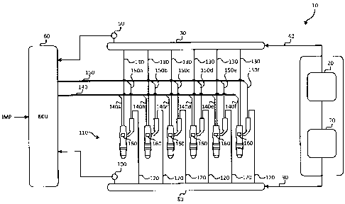
[0021] FIG. 1 is a schematic view of a fuel system according to one
embodiment.
[0022] FIG. 2 is a plot of an electronic control signal, a corresponding
hydraulic
pressure signal employed to activate a fuel injector in the fuel system of
FIG. 1, and a
mass flow signal representing the rate of mass flow through the fuel injector
due to the
hydraulic pressure signal.
[0023] FIG. 3 is a schematic view of a fuel injector trim apparatus for the
fuel system
of FIG. 1.
[0024] FIG. 4 is a plot of opening delay (OD) for a fuel injector versus a
fuel injector
family characteristic (XOD) representative of a nominal value of opening delay
for an
average fuel injector from a family of fuel injectors and determined as a
function of
engine operating conditions.
CA 02796614 2012-11-21
-11-
[0025] FIG. 5 is a plot of closing delay (CD) for a fuel injector versus a
fuel injector
family characteristic (XCD) representative of a nominal value of closing delay
for the
average fuel injector from the family of fuel injectors and determined as a
function of
engine operating conditions.
[0026] FIG. 6 is a plot of fuel trim (FTM) for a fuel injector versus a fuel
injector
family characteristic (XFTM) representative of a nominal value of fuel trim
for the average
fuel injector from the family of fuel injectors and determined as a function
of engine
operating conditions.
[0027] FIG. 7 is a plot of opening delay (OD) for a fuel injector versus a
fuel injector
family characteristic (XOD) representative of a nominal value of opening delay
for the
average fuel injector from the family of fuel injectors showing a low
load/speed trend and
a high load/speed trend.
[0028] FIG. 8 illustrates a plot of load versus speed illustrating a high load
region, a
low load region and a transition region for an internal combustion engine
employing the
fuel system of FIG. 1.
Detailed Description of Preferred Embodiment(s)
[0029] Referring to FIG. 1, there is shown fuel system 10 for a high pressure,
direct
injection internal combustion engine. Only the components relevant for the
understanding of the present technique are shown, as would be known by those
skilled in
the technology there are other components associated with a fuel system which
are not
shown. Although the disclosure herein is directed at a direct injection
system, the
technique described applies to any type of fuel injector. Gaseous fuel supply
apparatus
20 delivers pressurized gaseous fuel to gas rail 30 through piping 40. In the
present
disclosure gas refers to gaseous fuel. Gaseous fuel pressure in rail 30 is
monitored by
pressure sensor 50 which sends a signal to electronic controller 60 such that
the controller
CA 02796614 2012-11-21
-12-
commands apparatus 20 to pump gaseous fuel to maintain the pressure in rail 30
at a set
point pressure within a predetermined range of tolerance as a function of
engine
operating conditions. Liquid fuel supply apparatus 70 delivers pressurized
liquid fuel to
rail 80 through piping 90. The liquid fuel pressure in rail 80 is monitored by
pressure
sensor 100 which sends a signal to electronic controller 60 such that the
controller
commands apparatus 70 to pump liquid fuel to maintain the pressure in rail 80
at a set
point pressure within a predetermined range of tolerance as a function of
engine
operating conditions. In other embodiments a bias pressure between gaseous
fuel
pressure in rail 30 and liquid fuel pressure in rail 80 can be mechanically
controlled, for
example by a dome loaded regulator, such that by controlling the pressure of
one fuel the
other is automatically determined by the bias pressure. As is understood by
those
familiar with the technology, there are other related techniques for
controlling pressure in
rails 30 and 80.
[0030] In preferred embodiments, fuel injectors 110 are hydraulically actuated
direct
injectors that inject a pilot fuel and a main fuel, which can be actuated to
introduce the
pilot fuel separately and independently from the main fuel. In the present
embodiment
the pilot fuel is the liquid fuel in rail 80 delivered through piping 120 and
the main fuel is
the gaseous fuel in rail 30 delivered through piping 130. Control bus 140 from
controller
60 comprises control lines 140a, 140b, 140c, 140d, 140e, 140f which actuate
respective
fuel injectors 110 to inject gaseous fuel. Similarly, control bus 150 from
controller 60
comprises control lines 150a, 150b, 150c, 150d, 150e, 150f which actuate
respective fuel
injectors 110 to inject liquid fuel.
[0031] Referring now to FIGS. 1 and 2, the actuation of fuel injectors 110 is
described in more detail in relation to control line 140a of one such fuel
injector.
Controller 60 (from FIG. 1) actuates the fuel injector to introduce gaseous
fuel by
generating control signal 143a (shown in FIG. 2) sent over control line 140a
which
energizes an actuator in the injector (not shown) to initiate a pressure
change of hydraulic
CA 02796614 2012-11-21
- 13-
fluid characterized by hydraulic fluid pressure signal 144a. Control signal
143a is an
electrical control signal shown in its ideal form, such as a voltage or
current signal for
example. Hydraulic fluid pressure signal 144a actuates mechanisms of the
injector to
introduce gaseous fuel into combustion chambers (not shown) of the internal
combustion
engine, and the mass flow of the gaseous fuel into the combustion chambers is
illustrated
in FIG. 2 as mass flow signal 145a. Mass flow signal 145a is representative of
the rate of
fuel flowing into the combustion chambers. Control signal 143a is
characterized by
electronic pulse width (ePW), and mass flow signal 145a is characterized by
hydraulic
pulse width (hPW). The timing for electronic pulse width (ePW) begins at the
rising
edge of control signal 143a indicated as electronic start of injection (eSOI).
The timing
for hydraulic pulse width (hPW) begins at the rising edge of mass flow signal
145a
indicated as hydraulic start of injection (hSOI), and begins a period of time
known as
opening delay (OD) after electronic start of injection (eSOI). Hydraulic start
of injection
(hSOI) , which is an important parameter to control for improved combustion
quality,
correlates to the time fuel starts flowing through the injector into the
combustion
chamber, in direct injector embodiments. For this reason it is advantageous to
know the
opening delay (OD) for each fuel injector such that the time when fuel is
introduced can
be known with improved accuracy. Similarly, closing delay (CD) is the timing
difference
between the falling edge of control signal 143a and the corresponding falling
edge in
mass flow signal 145a. Opening delay (OD) and closing delay (CD) are
characteristics of
each fuel injector that vary from injector to injector. For the purposes of
this disclosure,
in FIG. 2, it is arbitrary whether opening delay (OD) is greater than, equal
to or less than
closing delay (CD). Depending upon the design and operating characteristics of
a
particular fuel injector, as well as the engine system operating conditions,
opening delay
(OD) could be greater than, equal to, or less than closing delay (CD).
[00321 Fuel injectors exhibit other characteristics that vary from part to
part. For a
given hydraulic pulse width (hPW) the actual quantity of fuel delivered from
each fuel
injector varies from a nominal value for the family of fuel injectors for a
variety of
CA 02796614 2012-11-21
- 14-
reasons, but primarily due to dimensional variances introduced by the
permitted
manufacturing tolerances. As used herein a family of fuel injectors comprises
like fuel
injectors. To compensate for this variation the hydraulic pulse width (hPW)
can be
corrected by increasing or decreasing the width. In the present disclosure the
hydraulic
pulse width is corrected by multiplying it by a correction factor called fuel
trim (FTM)
which will be described in more detail below. The present disclosure provides
a
technique to calibrate fuel injectors 110 such that a reduced amount of trim
information is
provided to electronic controller 60 whereby opening delay (OD), closing delay
(CD) and
fuel trim (FTM) can be determined for each fuel injector 110 as function of
engine
operating conditions as a function of the particular characteristics of each
individual fuel
injector.
[0033] Referring now to FIG. 3 fuel injector trim apparatus 200 comprises
opening
delay (OD) module 220, closing delay (CD) module 230, fuel trim (FTM) module
240
and correction module 250. As used herein, the terms module, algorithm and
step refer to
an application specific integrated circuit (ASIC), an electronic circuit, a
processor
(shared, dedicated, or group) and memory that execute one or more software or
firmware
programs, a combinational logic circuit, and/or other suitable components that
provide
the described functionality. In preferred embodiments the modules, algorithms
and steps
herein are part of electronic controller 60. Apparatus 200 operates to
determine
electronic start of injection (eSOI) and electronic pulse width (ePW) based on
a desired
hydraulic start of injection (hSOI) and a desired hydraulic pulse width (hPW).
Hydraulic
start of injection (hSOI) and hydraulic pulse width (hPW) are nominal values
for a
nominal fuel injector and are determined as a function of engine operating
conditions to
achieve a desired nominal fuelling at a desired nominal timing. For the
purposes of this
disclosure start of injection (SOI) refers to crank angle degrees (CA ) before
top dead
center (BTDC). Conventionally, controller 60 looks up in a map a corresponding
electronic pulse width (ePW) as a function of hydraulic pulse width (hPW) and
a
corresponding electronic start of injection (eSOI) as a function of hydraulic
start of
CA 02796614 2012-11-21
- 15-
injection (hSOI). In the present disclosure modules 220, 230 and 240 correct
opening
delay (OD), closing delay (CD) and hydraulic pulse width (hPW) respectively,
such that
electronic start of injection (eSOI) and electronic pulse width (eSOI) can be
determined
according to correction module 250.
[0034] Each module 220, 230 and 240 comprises a model representative of the
family
of fuel injectors 110 in the form of a multi-variable function that outputs a
value as a
function of engine operating conditions that is common to all fuel injectors
in that family.
Referring first to opening delay module 220, Eqn. 1 below illustrates the
multi-variable
function that determines a value (xoD) representative of the opening delay for
an average
fuel injector from the family of fuel injectors as a function of gaseous fuel
rail pressure
(GFRP), liquid fuel rail pressure (LFRP) and in-cylinder pressure (PCYL). The
derivation
of the mulit-variable function in EQN. 1 will be described in more detail
below, in
addition to the derivation of multi-variable functions EQNS. 3 and 5 discussed
in relation
to closing delay (CD) and fuel trim (FTM). The value (XOD) can be a nominal
opening
delay for the average fuel injector from the family of fuel injectors, or can
be a nominal
value having dimensions (units) that have no physical meaning but which is
correlated,
and therefore representative of the nominal opening delay. A corrected value
for opening
delay (OD) for a particular fuel injector can be determined by substituting
the value (XOD)
into EQN. 2, which is a function comprising constants (moD, boD) that are
characteristic
of the particular fuel injector. That is, EQN. 1 represents a relationship for
the family of
fuel injectors 110, and EQN. 2 represents a relationship for the particular
fuel injector.
The constants (moD, boD) for each fuel injector are determined in a
calibration phase
during manufacturing, described in more detail below.
XOD = f (GFRP, LFRP, Pcyl) EQN. 1
OD = moDxoD + boD EQN. 2
CA 02796614 2012-11-21
-16-
[0035] Referring now to closing delay module 230 in FIG. 3, Eqn. 3 below
illustrates
the multi-variable function that determines a value (XCD) representative of
the closing
delay for the average fuel injector from the family of fuel injectors as a
function of
gaseous fuel rail pressure (GFRP), liquid fuel rail pressure (LFRP), in-
cylinder pressure
(PCYL) and hydraulic pulse width (hPW). The value (XCD) can be a nominal
closing delay
for the average fuel injector from the family of fuel injectors, or can be a
nominal value
having dimensions (units) that have no physical meaning but which is
correlated, and
therefore representative of the nominal closing delay. A corrected value for
closing delay
(CD) for a particular fuel injector can be determined by substituting the
value (XCD) into
EQN. 4, which is a function comprising constants (mcD, bcD) that are
characteristic of the
particular fuel injector. That is, EQN. 3 represents a relationship for the
family of fuel
injectors 110, and EQN. 4 represents a relationship for the particular fuel
injector. The
constants (mcD, bcD) for each fuel injector are determined in the calibration
phase during
manufacturing, as will be described in more detail below.
XCD = f (GFRP, LFRP, Pcyl, hPW) EQN. 3
CD = mcDxcD + bCD EQN. 4
[0036] Referring now to fuel trim module 240 in FIG. 3, Eqn. 5 below
illustrates the
multi-variable function that determines a value (XFTM) representative of the
fuel trim for
the average fuel injector from the family of fuel injectors as a function of
gaseous fuel
rail pressure (GFRP), liquid fuel rail pressure (LFRP), in-cylinder pressure
(PCYL) and
hydraulic pulse width (hPW). The value (XFTM) can be a nominal fuel trim for
hydraulic
pulse width for the average fuel injector from the family of fuel injectors,
or can be a
nominal value having dimensions (units) that have no physical meaning but
which is
correlated, and therefore representative of the nominal fuel trim. Fuel trim
(FTM) is a
correction factor that scales hydraulic pulse width (hPW) due to variations in
fuelling
from injector to injector when identical hydraulic pulse widths are employed
to actuate
CA 02796614 2012-11-21
-17-
the injectors. A corrected value for fuel trim (FTM) for a particular fuel
injector can be
determined by substituting the value (XFTM) into EQN. 6, which is a function
comprising
constants (mFTM, bFTM) that are characteristic of the particular fuel
injector. That is,
EQN. 5 represents a relationship for the family of fuel injectors 110, and
EQN. 6
represents a relationship for the particular fuel injector. The constants
(mFTM, bFTM) for
each fuel injector are determined in the calibration phase during
manufacturing as will be
described in more detail below.
XFTM = f (GFRP, LFRP, Pyi, hPW) EQN. 5
FTM = mFTMxFTM + bFTM EQN. 6
[0037] Referring now to correction module 250, electronic start of injection
(eSOI)
and electronic pulse width (ePW) are calculated according to EQNS. 7 and 8
below.
Electronic start of injection (eSOI) and hydraulic start of injection (hSOI)
have units of
crank angle degrees before top dead center, and electronic pulse width (ePW)
and
hydraulic pulse width (hPW) have units of crank angle degrees in the present
disclosure
however other units are possible as would be understood by those familiar with
the
technology. Closing delay (CD) and fuel trim (FTM) can be combined into a
single
correction parameter in other embodiments since they both act to adjust
hydraulic end of
injection (hEOI) seen in FIG. 2.
eS01 = hSOI + OD EQN. 7
ePW = hPW * FTM + OD - CD EQN. 8
CA 02796614 2012-11-21
-18-
[0038] The multi-variable functions EQN. 1, 3 and 5 can be determined
theoretically
and empirically. In a preferred embodiment these equations are determined
empirically
according to the following technique. For a sample set of fuel injectors, from
the same
family of fuel injectors, fuel injection tests are conducted for each of the
injectors for a
predetermined number of engine operating conditions by varying at least the
following
parameters: liquid fuel rail pressure, gaseous fuel rail pressure, in-cylinder
pressure and
hydraulic pulse width. Preferably, the sample set of injectors are from a lot
of fuel
injectors obtained from a manufacturing facility. For each of the
predetermined engine
operating conditions opening delay (OD), closing delay (CD), hydraulic pulse
width and
actual quantity of fuel injected are measured. Fuel trim (FTM), that is the
hydraulic pulse
width correction factor, is determined based on the measured quantity of fuel
injected,
measured hydraulic pulse width, desired quantity of fuel injected and desired
hydraulic
pulse width. The predetermined engine operating conditions and corresponding
measured
data form sets of points {(GFRP, LFRP, Pcyl, hPW,OD)},
{(GFRP, LFRP, Pcy1, hPW,CD)}, and {(GFRP, LFRP, Pc ,1, hPW,FTM)} which when
plotted in multi-dimensional space form multi-dimensional surfaces
respectively. For
each of these surfaces, surface fitting techniques known to those skilled in
the technology
are employed to determine the multi-variable functions EQN. 1, 3 and 5
respectively. In
other embodiments instead of employing actual fuel injectors in real physical
tests,
models of the fuel injector and of the test environment can be employed to
determine the
sets of points described above. Preferably, the models of the fuel injectors
take into
consideration dimensional variations due to manufacturing tolerances. In the
event that
trim information is not provided for an actual fuel injector, for example trim
information
was not entered during injector replacement in the field, then the values
(XOD, XCD, XFTM)
can be employed in EQNS. 7 and 8 in place of opening delay (OD), closing delay
(CD)
and fuel trim (FTM) respectively. The values (XOD, XCD, XFTM) in this
situation are
normalized to represent the average opening delay, the average closing delay
and the
average fuel trim for the average fuel injector from the family of fuel
injectors. By this
technique an actual fuel injector for which trim data is not provided is
operated as an
CA 02796614 2012-11-21
-19-
average fuel injector, instead of an ideal fuel injector, which statistically
reduces fuelling
errors.
[00391 Referring now to FIGS. 4, 5 and 6 the derivation of the constants (moD,
boo),
(mcD, bcD) and (mFTM, bFTM) during a calibration procedure in manufacturing
will now
be described in more detail. As is known by those skilled in the technology,
after each
fuel injector 110 is assembled it can be installed into a testing apparatus
(not shown) in
which it can be actuated to inject fuel or a fluid with like properties. The
testing
apparatus comprises equipment and instrumentation to take measurements such
that mass
flow signal 145a and the actual injected quantity of fuel can be determined. A
predetermined number of engine operating conditions are selected, and for each
operating
condition the fuel injector is actuated and OD, CD and FTM are determined from
the
measurements taken with the test equipment. The XOD, xCDand XFTM values for
each of
the predetermined engine operating conditions are calculated according to EQN.
1, EQN.
3 and EQN. 5 respectively, and are paired with respective OD, CD and FTM
measurements. The pairs of points (xoD,OD), (XCD,CD) and (XFTM,FTM) are
assembled
into sets {(xoD,OD)}, {(xcD,CD)} and {(xFTM,FTM)} respectively, and these sets
are
plotted in graphs in FIGS. 4, 5 and 6 to illustrate the relationship between
the points.
Curve fitting techniques as known by those familiar with the technology are
employed to
determine the best fit lines 300, 310 and 320 through the sets {(xoD,OD)},
{(xcD,CD)}
and {(XFTM,FTM)} respectively. For each of the lines 300, 310 and 320 the
slopes (moD,
mcD, mFTM) and y-intercepts (boD, bcD, bFTM) are determined and stored on
recording
apparatus 160, as seen in FIG. 1, of fuel injector 110. In preferred
embodiments,
recording apparatus 160 for each fuel injector 110 is encoded with slopes
(moD, mcD,
mFTM) and y-intercepts (boD, bcD, bFTM) characteristic for that fuel injector.
Recording
apparatus 160 can be a bar code, a memory or an integrated circuit, as well as
other
components capable of storing information such that the information can be
retrieved or
displayed. The slopes (moD, mcD, mFTM) and y-intercepts (boD, bcD, bFTM) are
employed
in EQNS. 2, 4 and 6 during operation of the engine to determine opening delay
(OD),
CA 02796614 2012-11-21
-20-
closing delay (CD) and fuel trim (FTM) as a function of engine operating
conditions
(GFRP, LFRP, PCYL, hPW).
[0040] It is noteworthy to mention that in other embodiments lines 300, 310
and 320
may have shapes other than straight lines, such as lines that are parabolic or
hyperbolic in
shape, or lines that require a more complex polynomial or other functions to
represent
them. Factors influencing the shape of lines 300, 310 and 320 are the size of
the sets
{(xoD,OD)}, {(xcD,CD)} and {(XFTM,FTM)}, the number of variables in the multi-
variable functions EQNS 1, 3 and 5 and the characteristics of the family of
fuel injectors
for which calibration is performed, and therefore co-efficients other than
slope and y-
intercept may be determined and stored on recording apparatus 160. In general,
EQNS 2,
4 and 6 have a representation that is characteristic of the shape of the lines
300, 310 and
320 respectively.
[0041] Referring now to FIG. 7, a plot of the set {(xOD,OD)} is illustrated
for another
embodiment. There exist similar plots (not shown) for the sets {(xcD,CD)} and
{(XFTM,FTM)}. In this embodiment the characteristic behavior of fuel injectors
110
exhibit different trends between low load/speed, such as idle, and high
load/speed which
refers to any load and speed above low load/speed. Straight line 330 is the
best fit line
for the set {(xoD,OD)} at high load/speed and is characterized by slope mH,OD
and y-
intercept bH,oD according to EQN. 9. Straight line 340 is the best fit line
for the set
{(xoD,OD)} at low load/speed and is characterized by slope mL,OD and y-
intercept bL,OD
according to EQN. 10. Opening delay (OD) for a particular fuel injector at
high
load/speed can be determined by substituting the value (XOD) from EQN. 1 into
EQN. 9,
and opening delay (OD) at low load/speed can be determined by substituting the
value
(XOD) from EQN. 1 into EQN. 10. There are corresponding equations for closing
delay
(CD) and fuel trim (FTM).
ODH = mH,ODxOD + bH,OD EQN. 9
CA 02796614 2012-11-21
-21-
ODL = mL,ODxOD + bL,OD EQN. 10
[0042] When the engine is operating at a load/speed between low load/speed and
high
load and/or speed the values for opening delay (OD), closing delay (CD) and
fuel trim
(FTM) can be interpolated between their low load/speed and high load and/or
speed
values. A preferred interpolation technique is described herein. As would be
known to
those skilled in the technology there are other known interpolation techniques
which can
be employed. The plot in FIG. 8 illustrates the regions of the load/speed map
for the
engine applicable to straight lines 330 and 340. Region 350 is a high load
and/or speed
region characterized by slope mH,OD and y-intercept bH,OD = Region 360 is a
low
load/speed region characterized by slope mL.OD and y-intercept mL,OD. Region
370
represents a transition region between regions 350 and 360. In a preferred
embodiment,
the engine spends little time operating in transition region 370, for example
1-2% and is
normally operating in region 350. Although FIG. 8 illustrates a two
dimensional view, in
other embodiments there can be other transition zones between other axes, for
example
between gas rail pressure and speed, and gas rail pressure and load. Line 400
represents
the speed idle limit (SIL) and line 410 represents the speed non-idle limit
(SNIL), the
region between lines 400 and 410 represents the speed transition region
associated with
transition region 370. Line 420 represents the load idle limit (LIL) and line
430 represents
the load non-idle limit (LNIL), the region between lines 420 and 430
represents the load
transition region associated with transition region 370. When operating at a
load/speed
point in region 370, for example at point (S1,L1) in FIG. 8, the following
technique can be
performed to determine opening delay (OD), closing delay (CD) and fuel trim
(FTM).
The fraction that point (S1,LI) has entered speed transition region from speed
idle limit
(SIL) and the fraction that point (S1,L1) has entered load transition region
from load idle
limit (LIL) are calculated according to EQNS. 11 and 12 below respectively. A
fractional
value from EQNS. 11 and 12 that is less than zero is interpreted as zero, and
when more
than two axes are employed (load, speed, gas rail pressure) a fractional value
that is
greater than one is interpreted as one. Of the two fractions Fs and FL maximum
fractional
CA 02796614 2012-11-21
-22-
value FM is selected according to EQN. 13. Opening delay (OD), closing delay
(CD) and
fuel trim (FTM) are then calculated according to EQNS. 14, 15 and 16. Values
XOD, XCD
and XFTM are determined according to EQNS. 1, 3 and 5, based on engine
operating
conditions at point (S1,L1), such that opening delays (ODL, ODH), closing
delays
(CDL, CDH) and fuel trims (FTML, FTMH) in EQNS. 14, 15 and 16 can be
determined. In
EQN. 14, ODL is the opening delay corresponding to the value XOD in low load
and speed
region 360, and ODH is the opening delay corresponding to the value XOD in
high load
and/or speed region 350. In EQN. 15, CDL is the closing delay corresponding to
the
value XCD in low load and speed region 360, and CDH is the closing delay
corresponding
to the value XCD in high load and/or speed region 350. In EQN. 16, FTML is the
fuel trim
corresponding to the value XFTM in low load and speed region 360, and FTMH is
the fuel
trim corresponding to the value XFTM in high load and/or speed region 350.
Sl-SIL EQN. 11
FS SNIL-SIL
Ll-LIL EQN. 12
FL =
LNIL-LIL
FM = max (FS, FL) EQN. 13
OD = ODL + FM X (ODH - ODL) EQN. 14
CD = CDL + FM x (CDH - CDL) EQN. 15
FTM = FTML + FM x (FTMH - FTML) EQN. 16
[00431 While particular elements, embodiments and applications of the present
invention have been shown and described, it will be understood, that the
invention is not
limited thereto since modifications can be made by those skilled in the art
without
departing from the scope of the present disclosure, particularly in light of
the foregoing
teachings.