Note: Descriptions are shown in the official language in which they were submitted.
CA 02797209 2012-11-29
=
253803-2
COOLING SYSTEM FOR GAS TURBINE LOAD COUPLING
DESCRIPTION
FIELD OF THE INVENTION
The present disclosure relates generally to gas turbines such as in
particular, but
not exclusively, to aeroderivative gas turbines. More specifically, the
disclosure relates to
industrial applications of aeroderivative gas turbines, for power generation,
natural gas
liquefaction or similar industrial applications.
DESCRIPTION OF THE RELATED ART
Aeroderivative gas turbines are widely used as power sources for mechanical
drive
applications, as well as in power generation for industrial plants, pipelines,
offshore
platforms, LNG applications and the like.
Fig. 1 illustrates a schematic representation of a system including a gas
turbine
and a load mechanically driven by said gas turbine. More specifically, in the
diagrammatic representation of Fig. 1 reference 1 indicates a gas turbine
which drives a
load, for example a compressor or a compressor train for a natural gas
liquefaction line,
schematically shown at 3. The gas turbine 1 is connected to the load 3 by
means of a load
coupling 5. The load coupling 5 comprises a shaft 7 and a joint 9. In the
example of Fig. 1
the shaft 7 rotatingly driven by the gas turbine 1 is connected to a gear box
11. An output
shaft 13 of said gear box 11 connects the gear box 11 to the load 3. The load
3 can
include a single rotary machine, e.g. a compressor, or an electric generator,
or else a set of
rotary machines on the same shaft. A further gear box can be arranged between
two
adjacent rotary machines driven by the turbine 1.
- 1 -
, CA 02797209 2012-11-29
253803-,2
The gas turbine 1 comprises a gas generator 15 and a power turbine 17. The gas
generator 15 comprises in turn a compressor 19, a combustion chamber 21 and a
high
pressure turbine 23. The air entering the compressor 19 is compressed at high
pressure
and added with a liquid or gaseous fuel in the combustion chamber 21. The
compressed
and high temperature combustion gases are expanded first in the high pressure
turbine 23,
which is connected through an internal shaft 25 to the compressor 19. The
expansion of
the combustion gasses in the high pressure turbine 23 generates mechanical
power, which
drives into rotation the compressor 19. The partly expanded combustion gasses
exiting
the high pressure turbine 23 enter the power turbine 17 and further expand to
generate
mechanical power, which drives the load 3 through the load coupling 5. The
exhausted
combustion gasses are collected by a collector-diffuser and discharged through
a
discharge line 27.
In the example shown in Fig. 1 the gas turbine is a single shaft gas turbine,
i.e. a
gas turbine wherein a single internal shaft 25 connects the high pressure
turbine 23 to the
compressor 19 of the gas generator 15. The power turbine, sometimes also named
low
pressure turbine, is supported by a shaft that is separate from the internal
shaft 25 such
that the gas generator 15 can rotate independently of and at a different speed
than the
power turbine 17. Other gas turbine embodiments provide for a different number
of
internal shafts and the gas generator can comprise a different number of
compressors and
turbines driving the compressors.
These turbines are typically aeroderivative turbines.
In the exemplary embodiment of Fig. 1 the load 3 is connected through the load
coupling 5 to the so-called hot end of the gas turbine 1, i.e. the gas turbine
side where the
power turbine 17 is arranged, to be distinguished from the cold end,
corresponding to the
side of compressor 19.
The load coupling 5 is subject to temperature deformations due to high
temperature at the hot end of the gas turbine 1. Thermal deformation of the
shaft 7 must
- 2 -
. CA 02797209 2012-11-29
253803-2
be sagged, i.e. measures must be adopted to prevent the thermal expansion of
the shaft 7
to damage the load bearings of either the power turbine 17 or the machinery
arranged on
the load side, i.e. the bearings of the gear box 11 (if present) and/or of the
rotary machines
3 driven by the gas turbine 1. Commonly adopted measures include arranging a
joint
which can compensate for the thermal expansion of the shaft. Thermal expansion
of the
shaft nevertheless generates axial forces on the bearings on both sides of the
joint, i.e. on
the turbine bearings and on the gearbox or rotary machine bearings.
JP-2000-291446 discloses a gas turbine with a load-coupling cooling system,
including fan blades mounted on the load coupling. The fan blades are driven
into
rotation by the load coupling and generate a stream of cooling air from the
environment
through a guard surrounding the load coupling. Using fan blades driven by the
load
coupling removes the need for an additional compressor or fan for cooling the
load
coupling. However, the blades modify the rotodynamic behavior of the load
coupling and
can negatively affect the correct operation thereof, leading to dynamic
stresses, vibration
and potential failure of the rotating components and relevant supports.
A need therefore exists for a more efficient load-coupling cooling system.
SUMMARY OF THE INVENTION
As will be described here below, reference being made to some embodiments of
the invention, a particularly efficient arrangement is provided for delivering
a stream of
cooling air in a volume at least partly surrounding at least a portion of the
load coupling
connecting the gas turbine and the load, heat is actively removed by forced
air convection
from the load coupling, thus reducing the thermal deformation of the load
connection and
therefore reducing the axial load on the turbine and load bearings.
According to some embodiments of the subject matter disclosed herein, a gas
turbine is provided, said gas turbine comprising at least: a compressor; a
power turbine; a
load coupling connecting the gas turbine to a load; a load-coupling guard at
least partly
- 3 -
CA 02797209 2012-11-29
253803-2
surrounding the load coupling; a cooling air channeling designed and arranged
to
circulate cooling air flow in said load-coupling guard sufficient to remove
heat from said
load coupling. The forced air convection provided in the load-coupling guard
removes
heat from the load coupling and maintains the load coupling at low
temperature, thus
reducing the overall thermal deformation of the load coupling. In this way
axial loads
generated by thermal expansion of the load bearing are reduced also when the
gas turbine
is connected to the load via said load coupling on the hot end of the gas
turbine, i.e. on
the side of the power turbine rather than on the side of the compressor.
More specifically, the present disclosure provides a gas turbine comprising: a
compressor; a power turbine and a load coupling which connects the gas turbine
to a load
(37). A gas turbine package is further provided, comprised of a turbomachinery
compartment housing the gas turbine. A load-coupling guard is arranged around
the load
coupling to at least partly surrounding said load coupling. A cooling air
circulation
system is arranged and configured for circulating cooling air in the
turbomachinery
compartment. The cooling air circulation system delivers fresh ambient air in
the
turbomachinery compartment to cool the turbomachine casing, i.e. the casing of
the
compressor and of the turbine(s) arranged therein. Moreover, a cooling air
channeling is
also provided for cooling the load coupling. The cooling air channeling is
designed and
arranged to circulate a cooling air flow taken from the cooling air
circulation system in
the load-coupling guard. The air flow circulating in the load-coupling guard
is sufficient
to remove heat from said load coupling and reduce the thermal and mechanical
stresses
thereof. In some embodiments, the cooling air channeling is designed and
configured to
divert a fraction of the ambient air delivered by the cooling air circulation
system
upstream of the turbomachinery compartment, i.e. before the fresh ambient air
enters the
turbomachinery compartment. The air delivered by the cooling air channeling
towards the
load-coupling guard is thus nearly at ambient temperature, thus achieving
improved
cooling of the load coupling.
- 4 -
CA 02797209 2012-11-29
253803-2
A single air forcing device can be arranged and designed for forcing cooling
air in
the turbomachinery compartment and through the cooling air channeling in said
load-
coupling guard. A simple construction with a limited number of auxiliary
facilities is thus
required to perform cooling of both the turbomachinery casing and the load
coupling. The
efficiency of the system is improved, the overall reliability thereof is
enhanced. A more
compact arrangement is also achieved. A separate air forcing device for
delivering
cooling air to the load coupling can be dispensed with, since the cooling air
flow around
the load coupling is generated by the same air forcing device which is
provided for
turbomachinery cooling. Additionally, no fan blades are required to be mounted
on the
load coupling, as in the above mentioned prior art arrangements.
In some embodiments an air intake line or duct can be provided and arranged in
fluid communication with the cooling air circulation system and with said
cooling air
channeling. The air intake line can be provided with a filter arrangement at
the inlet
thereof. The filter arrangement filters both the ambient air required for
cooling the
turbomachinery casing, as well as the ambient air required for cooling the
load coupling.
No separate filter arrangement is required. In some embodiments, the air
intake line is in
fluid communication with an air intake plenum, from which combustion air
enters the
compressor of the gas generator of the gas turbine. This further improves the
efficiency of
the system reducing the costs thereof, as a single filter arrangement filters
the entire
cooling air flow as well as the combustion air flow.
Further embodiments and advantageous features of a gas turbine according to
the
subject matter disclosed herein are described here below.
In some preferred embodiments, the gas turbine is an aeroderivative gas
turbine.
The gas turbine can be a single-shaft gas turbine, i.e. a gas turbine wherein
the
compressor is mechanically driven by a high pressure gas turbine, wherein the
compressor and the high pressure gas turbine are supported on a common shaft.
The
compressor and high pressure gas turbine form a gas generator. The exhaust
combustion
- 5 -
CA 02797209 2012-11-29
253803-2
gases exiting the high pressure turbine are further expanded in the power
turbine. The
power turbine is supported on an independent shaft and drives into rotation a
load. In
some embodiments a gear box is arranged between the power turbine and the
load.
In other embodiments the gas turbine can be a dual-shaft or a three-shaft gas
turbine, comprising two or three compressors and two or three turbines, with
co-axial
shafts connecting the turbines and shafts to one another.
Irrespective of the number of compressors and turbines, and from the number of
co-axial shafts, a load coupling is provided between the power turbine, i.e.
the turbine
providing power to drive the load, and the load, with possible interposition
of a gear box
to drive the load and the power turbine at different rotational speeds. The
load coupling
commonly comprises at least a shaft and one or more joints. The shaft can be
comprised
of one or more shaft sections or shaft portions, connected to one another.
In some embodiments the load coupling and the load-coupling guard extend
through an exhaust gas plenum or exhaust collector-diffuser assembly, which at
least
partly surrounds said load coupling and said load-coupling guard. The exhaust
collector-
diffuser assembly develops around the axis of the gas turbine and collects the
exhausted
and expanded combustion gases to discharge them in the environment or convey
the
expanded, high temperature combustion gases e.g. towards a steam turbine or
another
section of a co-generation plant.
In some embodiments, the gas turbine is at least partly arranged in a gas
turbine
package comprised of a turbomachinery compartment housing said gas turbine. In
some
embodiments, an air circulation system is further provided, for circulating
cooling air in
the turbomachinery compartment. A load compartment is preferably arranged
downstream the turbomachinery compartment. The load compartment is arranged on
a
side of the turbomachinery compartment. An opposite air intake plenum is
arranged on
the opposite side of the turbomachinery compartment, to allow air in the
compressor of
the gas turbine and in the turbomachinery compartment, to cool the exterior of
the
- 6 -
CA 02797209 2012-11-29
253803-2
turbomachinery casing. The load coupling which connects the gas turbine and
the load
preferably extends through the load compartment. The load-coupling guard may
receive
air from the cooling air circulation system or other dedicated sources.
The cooling air channeling can comprise an air port, wherein cooling air from
said
cooling air circulation system is forcedly circulated. At least a first
ventilation duct fluidly
connects said air port to said load-coupling guard and in some embodiments a
second and
possibly a third ventilation duct is provided, in fluid communication with the
load
compartment to allow forced air circulation in said load compartment.
The load-coupling guard can be open ended at both ends, such that the air
forcedly
circulating in the volume delimited by the load-coupling guard can escape at
both ends of
the load-coupling guard. This enhances cooling of the load coupling also in
portions
thereof extending outside the load-coupling guard.
According to a further aspect, the subject matter disclosed herein relates to
a
method of reducing heat and mechanical stresses on a load coupling in a gas
turbine, said
gas turbine comprising: at least a compressor; a power turbine; and a load
coupling
connecting said gas turbine to a load. According to some embodiments, the
method
comprises removing heat from the load coupling by forcing cooling air around
said load
coupling.
In some embodiments, a method is provided, for reducing heat and mechanical
stresses on a load coupling in a gas turbine. The method advantageously
comprises the
following steps: generating a cooling air stream to cool a casing of the gas
turbine;
diverting a fraction of the cooling air stream upstream of a turbomachinery
compartment
where the gas turbine is arranged, and forcing said fraction of cooling air
stream around a
load coupling, which connects the gas turbine to a load, for removing heat
from said load
coupling.
- 7 -
. CA 02797209 2012-11-29
253803-2
In some embodiments, the method comprises the steps oE defining a confined
volume at least partly surrounding the load coupling; and forcedly circulating
cooling air
in said confined volume to remove heat from the load coupling. It shall be
understood
that heat is usually removed from one portion of the load coupling only, i.e.
the portion
nearest to the hot end of the gas turbine, since thermal expansion is
concentrated in said
section of the load coupling.
In an exemplary embodiment of the subject matter disclosed herein the method
comprises the steps of: arranging a load-coupling guard at least partly
surrounding the
load coupling, the confined volume being at least partly delimited by the load-
coupling
guard; and forcedly circulating cooling air between said load coupling and
said load-
coupling guard, whereby removing heat from said load coupling.
In further embodiments, the method can additionally comprise the step of
causing
cooling air to escape from the confined volume at at least a first end of said
load-coupling
guard facing said power turbine, whereby a stream of cooling air exiting said
confined
volume at said first end of said load-coupling guard is directed against said
power turbine.
In some embodiments the method can further comprise the step of causing
cooling air to
escape from said confined volume at at least a second end of said load-
coupling guard
facing said load, whereby a stream of cooling air exiting said confined volume
at said
second end of said load-coupling guard is directed away from said power
turbine and
towards said load. The second end of the load-coupling guard can open toward
the
environment, i.e. outside the turbine package.
According to some exemplary embodiments, the method comprises the steps of:
arranging the gas turbine in a gas turbine package; generating a cooling air
stream to cool
a casing of said gas turbine; deviating a fraction of said cooling air stream
towards the
confined volume partly surrounding the load coupling.
The gas turbine package usually also comprises a load compartment between the
gas turbine and the load. The load coupling and the confined volume
surrounding said
- 8 -
253803-2
load coupling can be arranged at least partly in said load compartment and
cooling air can
be circulated partly also in said confined volume and partly in said load
compartment.
Features and embodiments are disclosed here below and are further set forth in
the
appended claims, which form an integral part of the present description. The
above brief
description sets forth features of the various embodiments of the present
invention in
order that the detailed description that follows may be better understood and
in order that
the present contributions to the art may be better appreciated. There are, of
course, other
features of the invention that will be described hereinafter and which will be
set forth in
the appended claims. In this respect, before explaining several embodiments of
the
invention in details, it is understood that the various embodiments of the
invention are not
limited in their application to the details of the construction and to the
arrangements of the
components set forth in the following description or illustrated in the
drawings. The
invention is capable of other embodiments and of being practiced and carried
out in
various ways. Also, it is to be understood that the phraseology and
terminology employed
herein are for the purpose of description and should not be regarded as
limiting.
As such, those skilled in the art will appreciate that the conception, upon
which the
disclosure is based, may readily be utilized as a basis for designing other
structures,
methods, and/or systems for carrying out the several purposes of the present
invention. It
is important, therefore, that the claims be regarded as including such
equivalent
constructions insofar as they do not depart from the scope of the present
invention.
BRIEF DESCRIPTION OF THE DRAWINGS
A more complete appreciation of the disclosed embodiments of the invention and
many of the attendant advantages thereof will be readily obtained as the same
becomes
better understood by reference to the following detailed description when
considered in
connection with the accompanying drawings, wherein:
- 9 -
CA 2797209 2017-09-29
. CA 02797209 2012-11-29
253803-2
Fig. 1 illustrates a gas turbine and compressor arrangement according to the
state
of the art;
Fig. 2 illustrates a gas turbine and compressor arrangement embodying the
subject
matter disclosed herein;
Fig. 3 illustrates a schematic section according to a vertical plane of the
arrangement of Fig. 2;
Fig. 4 illustrates a cross-section according to line IV-IV in Fig. 3; and
Fig. 5 illustrates further embodiment of a gas turbine and load arrangement
according to the present disclosure.
DETAILED DESCRIPTION OF EMBODIMENTS OF THE INVENTION
The following detailed description of the exemplary embodiments refers to the
accompanying drawings. The same reference numbers in different drawings
identify the
same or similar elements. Additionally, the drawings are not necessarily drawn
to scale.
Also, the following detailed description does not limit the invention.
Instead, the scope of
the invention is defined by the appended claims.
Reference throughout the specification to "one embodiment" or "an embodiment"
or "some embodiments" means that the particular feature, structure or
characteristic
described in connection with an embodiment is included in at least one
embodiment of
the subject matter disclosed. Thus, the appearance of the phrase "in one
embodiment" or
"in an embodiment" or "in some embodiments" in various places throughout the
specification is not necessarily referring to the same embodiment(s). Further,
the
particular features, structures or characteristics may be combined in any
suitable manner
in one or more embodiments.
- 10 -
CA 02797209 2012-11-29
253803-2
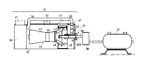
Fig. 2 schematically illustrates a system embodying the subject matter
disclosed
herein. The system comprises a gas turbine and a load connected to the gas
turbine by
means of a load coupling. More specifically in the diagrammatic representation
of Fig. 2,
a gas turbine package 31 comprising a gas turbine 33 is connected by means of
a load
coupling 35 to a load 37. In the exemplary embodiment illustrated in Fig. 2
the load 37 is
represented as a compressor, such as a compressor for a refrigerant of a
natural gas
liquefaction system. In the exemplary embodiment illustrated in Fig. 2 a
gearbox 38 is
arranged between the gas turbine and the compressor 37. The compressor 37 can
be one
of a series of compressors forming a compressor train driven by the same gas
turbine 33.
It shall be understood that a different kind of load can be driven by the gas
turbine. For
example the load can be an electric generator of a power generation plant. The
load
coupling can include one or more gearboxes and/or one or more rotary machines,
such as
electric machines or turbomachines.
In the exemplary embodiment shown in Fig. 2, the gas turbine package 31
comprises an air intake plenum 39 in fluid communication with an air intake
line 41 and
with the inlet side of a compressor 43 of the gas turbine 33. The gas turbine
33 can be
comprised of a high pressure turbine 45 and a power turbine 47. The high
pressure turbine
45 is drivingly connected to the compressor 43 by an internal shaft (not
shown).
Combustion gases generated in the combustion chamber of the gas turbine expand
sequentially in the high pressure turbine 45 to generate the power required to
drive the
compressor 43 and subsequently in the power turbine 47, to drive the load 37.
Different
gas turbine arrangements can be used, for example including two or more
compressor in
sequence and more than two turbines in series on the hot side of the gas
turbine 33. In
general terms, the gas turbine 33 comprises a gas generator comprised of at
least one
compressor 43 and a high pressure turbine 45, said gas generator providing
combustion
gases at high temperature and high pressure, which are expanded in one or more
turbines
47.
-11-
, CA 02797209 2012-11-29
253803-2
In some embodiments the gas turbine 33 can be an aeroderivative gas turbine.
The
overall structure and layout, including the number of compressors, the number
of
turbines, the number of shafts, the number of compression and expansion stages
of the
aeroderivative gas turbine can vary from one aeroderivative gas turbine to the
other.
Suitable aeroderivative gas turbines are LM2500+G4 LSPT or LM2500
aeroderivative
gas turbines, both commercially available from GE Aviation, Evendale, Ohio,
USA.
Other suitable aeroderivative gas turbines are the PGT25+G4 aeroderivative gas
turbine
commercially available from GE Oil and Gas, Florence, Italy, or the Dresser-
Rand
Vectra0 40G4 aeroderivative gas turbine commercially available from Dresser-
Rand
Company, Houston, Texas, USA, for example. In other embodiments, the
aeroderivative
gas turbine can be a PGT16, a PGT 20, all commercially available from GE Oil
and Gas,
Florence, Italy or an LM6000 aeroderivative gas turbine, commercially
available from GE
Aviation, Evendale, Ohio, USA.
The expanded and exhausted combustion gases are collected in an exhaust
diffuser-collector assembly 49 and discharged towards the environment through
a
discharge line 51.
In the exemplary embodiment shown in the drawings, the exhaust diffuser-
collector assembly 49 is arranged in a load compartment 53. The load
compartment 53 is
arranged at the opposite side of the gas turbine package 31 with respect to
the intake
plenum 39, i.e. at the hot end side of the gas turbine. The load coupling 35
extends from
the power turbine 47 through the exhaust diffuser-collector assembly 49 which
therefore
at least partly surrounds the load coupling 35.
Part of the air sucked through the air intake plenum 39 at the cold end side
of the
gas turbine 33 flows through the gas turbine package 31 and more specifically
through a
turbomachinery compartment 55 forming the intermediate portion of the gas
turbine
package 31 and housing at least partly the gas turbine 33. The air circulating
in the
- 12-
CA 02797209 2012-11-29
253803-2
turbomachinery compartment 55 cools the casing of the turbine machinery and is
exhausted through an exhaust cooling air line 57.
In some embodiments, part of the cooling air sucked in the turbomachinery
compartment 55 is deviated in an air duct 59 which is in fluid communication
with an air
port 61.
In the exemplary embodiment shown in the drawing, an air ventilation duct 63
fluidly connects the air port 61 with a load-coupling guard 65, the structure
of which can
best be seen in Fig. 3. In some embodiments the load-coupling guard 65 is
comprised of a
cylindrical shell or sleeve 67 surrounding at least partly a shaft 69 forming
part of the load
coupling 35.
In some embodiments the load-coupling guard 65 comprises a first end 65A
facing
towards the gas turbine 33 and a second end 65B facing the load 37. At least
one end and
preferably both ends 65A and 65B can be open such that cooling air which is
forcedly
circulated through the air port 61 and the ventilation duct 63 escapes from a
confined
volume or space delimited by the cylindrical shell or sleeve 67 of the load-
coupling guard
65, said volume being indicated with reference number 70. In some embodiments
the first
end 65A of the load-coupling guard is oriented such that air escaping the
first end 65A is
forced against the exhaust diffuser-collector assembly 49. In some embodiments
the
second end 65B of the load-coupling guard 65 can be open towards the
environment,
outside the turbine package, such that a part of the cooling air forcedly
circulating in the
confined volume surrounding the load coupling is vented in the environment.
In some embodiments the air port 61 is additionally in fluid communication
with a
second ventilation duct 64 and possibly with a third ventilation duct 66 (see
Fig. 4).
The second and third ventilation ducts 64 and 66 comprise open ends arranged
in
the load compartment 53, such that air forced into the ventilation ducts 64,
66 is vented in
- 13 -
CA 02797209 2012-11-29
253803-2
the load compartment 53. The air circulating in the load compartment cools the
load
compartment 53 and any apparatus arranged therein.
With the above described arrangement, cooling air forced by the cooling air
circulating system through the air duct 59 is caused to enter the first
ventilation duct 63 as
well as the second and/or third ventilation ducts 64 and 66, if present. The
air stream
conveyed by the first ventilation duct 63 into the volume 70 surrounding the
load
coupling 35 cools the load coupling 35 and more specifically the shaft 69
surrounded by
the load-coupling guard 65. An air flow escaping from both ends 65A and 65B of
the
load-coupling guard 65 is forced to remove heat also from both portions of the
shaft 69
extending from the load-coupling guard 65 and of one or more joints arranged
on said
shaft 69 outside of the load-coupling guard 65. Additionally, the air escaping
from the
open end 65A of the load-coupling guard 65 is oriented towards the exhaust
diffuser-
collector assembly 49, maintaining the temperature in the area surrounding the
load
coupling 35 at a reduced temperature.
The temperature of the cooling air and the rate of the cooling air flow are
advantageously such as to maintain the temperature of the load coupling 35 and
more
specifically of the shaft 69 at such a value to reduce substantially the axial
load on the
bearings of the shaft both on the turbine side as well as on the load side.
As can be appreciated in particular from Fig. 3 in some embodiments the open
end
65A of the load-coupling guard 65 is arranged within the hollow part of the
exhaust
diffuser-collector assembly 49 through which the load coupling 35 extends. In
this
manner an efficient cooling air stream exiting the tubular load-coupling guard
65 is
directed along the proximal end of the shaft 69, and possibly a joint 69A
arranged
between the shaft 69 and the hot end of the gas turbine 33 just in that area
where the
highest heat load is present, said heat load being caused by the hot exhausted
gasses
collected by the exhaust diffuser-collector assembly 49 and deviated towards
the
discharge line 51.
- 14 -
CA 02797209 2012-11-29
253803-2
Fig. 4 schematically illustrates a further joint 69B arranged on the load
coupling
35 in the area of the second open end 65B of the load-coupling guard 65. Also
in this
area, the forced cooling air stream escaping the open end 658 provides for an
efficient
cooling of this area of the load coupling 35.
Fig. 5 schematically illustrates a further embodiment of the gas turbine and
load
arrangement according to the present disclosure. The same reference numbers
are used to
designate the same or similar parts, components or elements described here
above in
connection with Fig. 2.
The system comprises a gas turbine package 31 comprising a gas turbine 33 is
connected by means of a load coupling 35 to a load 37. In the exemplary
embodiment
illustrated in Fig. 5 the load 37 comprises again a compressor, e.g. a
compressor for a
refrigerant of a natural gas liquefaction system. A gearbox 38 can be arranged
between
the gas turbine and the compressor 37. In other embodiment a direct drive
between the
gas turbine and the load can be provided or a different speed manipulation
device can be
used instead of a gearbox. The compressor 37 can be one of a series of
compressors
forming a compressor train driven by the same gas turbine 33. It shall be
understood that
a different kind of load can be driven by the gas turbine. For example the
load can be an
electric generator of a power generation plant. The load coupling can include
one or more
gearboxes and/or one or more rotary machines, such as electric machines or
turbomachi nes.
The gas turbine package 31 comprises an air intake plenum 39 in fluid
communication with an air intake line or duct 41 and with the inlet side of a
compressor
43 of the gas turbine 33. A filter arrangement 42 usually provided at the
inlet of the air
intake line or duct 41 is also shown in Fig. 5.
The gas turbine 33 can be comprised of a high pressure turbine 45 and a power
turbine 47. The high pressure turbine 45 is drivingly connected to the
compressor 43 by
an internal shaft (not shown). Combustion gases generated in a combustion
chamber 44
- 15 -
253803-2
of the gas turbine expand sequentially in the high pressure turbine 45 to
generate the
power required to drive the compressor 43 and subsequently in the power
turbine 47, to
drive the load 37. Different gas turbine arrangements can be used, for example
including
two or more compressor in sequence and more than two turbines in series on the
hot side
of the gas turbine 33. In general terms, the gas turbine 33 comprises a gas
generator
comprised of at least one air compressor 43 and a high pressure turbine 45,
said gas
generator providing combustion gases at high temperature and high pressure,
which are
expanded in one or more power turbines 47. The power turbine(s) can be
mechanically
connected to the shaft of the high pressure turbine and compressor. In
alternative
embodiments, the power turbine 47 can be mechanically separate from the gas
generator,
i.e. the gas generator shaft and the power turbine shaft can be mechanically
independent
from one another.
The expanded and exhausted combustion gases are collected by an exhaust
diffuser-
collector assembly 49 and discharged towards the environment through a
discharge line or
stack 51.
The exhaust diffuser-collector assembly 49 can be arranged in a load
compartment
53, which is arranged opposite the intake plenum 39, i.e. at the hot end side
of the gas
turbine 33. The load coupling 35 extends from the power turbine 47 through the
exhaust
diffuser-collector assembly 49 which therefore at least partly surrounds the
load coupling
35.
Combustion air is sucked through the filter arrangement 42 and the air intake
line
or duct 41 in the intake plenum 39 by the compressor 43.
Through the same air intake line or duct 41 and the filter arrangement 42
fresh
ambient air is also delivered towards the interior of the gas turbine package
31, and more
specifically through the turbomachinery compartment 55 for cooling purposes.
Fresh
ambient air is further delivered from the air intake line or duct 41 towards a
load-coupling
cooling arrangement, as will be described in greater detail here below.
- 16 -
CA 2797209 2017-09-29
, CA 02797209 2012-11-29
253803-2
In some embodiments, a single fan, compressor, or any other air forcing or air
propelling device, schematically shown at 46, is provided in a ventilation air
duct 48,
which is in fluid communication with the air inlet line 41. An air forcing or
air propelling
device shall be understood as any device suitable to deliver a sufficient air
flowrate at a
sufficient air pressure for the purposes described here below. Air sucked by
the fan 46
from the air inlet line 41 is forced or propelled through a duct 55A to a
turbomachinery
compartment 55 forming the intermediate portion of the gas turbine package 31
and at
least partly housing the gas turbine 33. The air circulating in the
turbomachinery
compartment 55 cools the casing of the turbine machinery and is exhausted
through an
exhaust cooling air line 57.
In some embodiments, part of the cooling air sucked in the turbomachinery
compartment 55 is deviated in an air duct 59 which is in fluid communication
with an air
port 61. In the exemplary embodiment shown in Fig. 5, an air ventilation duct
63 fluidly
connects the air port 61 with a load-coupling guard 65, which can have the
same structure
disclosed here above in connection with Figs 2 to 4. In some embodiments the
load-
coupling guard 65 is comprised of a cylindrical shell or sleeve 67 at least
partly
surrounding a shaft 69 forming part of the load coupling 35.
Also in the embodiment of Fig. 5 the guard 65 comprises a first end 65A facing
towards the gas turbine 33 and a second end 65B facing the load 37. At least
one end and
preferably both ends 65A and 65B can be open, so that cooling air circulating
through the
air port 61 and the ventilation duct 63 escapes from a confined volume or
space 70
delimited by the cylindrical shell or sleeve 67 of the load-coupling guard 65.
In some
embodiments the first end 65A of the load-coupling guard is oriented so that
air escaping
the first end 65A is forced against the exhaust diffuser-collector assembly
49. In some
embodiments the second end 65B of the load-coupling guard 65 can be open
towards the
environment, outside the turbine package, so that a part of the cooling air
forcedly
circulating in the confined volume surrounding the load coupling is vented in
the
environment.
- 17-
CA 02797209 2012-11-29
253803-2
In some embodiments the air port 61 is additionally in fluid communication
with a
second ventilation duct 64 and possibly additional ventilation ducts, not
shown. The
ventilation duct(s) 64 opens in the load compartment 53, so that air forced
into the
ventilation duct 64 is vented in the load compartment 53. The air circulating
in the load
compartment cools the load compartment 53, the surface of exhaust collector-
diffuser
assembly 49 and any apparatus arranged in the load compartment 53.
In the embodiments of both Figs 2-4 and Fig. 5 a single air source is
therefore
provided, for delivering cooling air through the gas turbine package and the
turbomachinery compartment 55 in particular, as well as to the load-coupling
guard
surrounding the load coupling. A single fan, compressor or ventilator can be
provided for
forcedly circulating cooling air both around the turbomachine casing in the
turbomachinery compartment 55 as well as around the load coupling. Preferably
the air is
taken from the air inlet line or duct 41.
In preferred embodiments, a single filter arrangement 42 is provided for
filtering
both the combustion air ingested by the compressor 43 of the gas turbine 33,
as well as
the cooling air circulating in the gas turbine package, and specifically in
the
turbomachinery compartment 55 for cooling the turbomachine casing, as well as
around
the load coupling.
A compact arrangement having reduced manufacturing and maintenance costs is
obtained.
While the disclosed embodiments of the subject matter described herein have
been
shown in the drawings and fully described above with particularity and detail
in
connection with several exemplary embodiments, it will be apparent to those of
ordinary
skill in the art that many modifications, changes, and omissions are possible
without
materially departing from the novel teachings, the principles and concepts set
forth
herein, and advantages of the subject matter recited in the appended claims.
Hence, the
proper scope of the disclosed innovations should be determined only by the
broadest
- 18-
CA 02797209 2012-11-29
253803-2
interpretation of the appended claims so as to encompass all such
modifications, changes,
and omissions. In addition, the order or sequence of any process or method
steps may be
varied or re-sequenced according to alternative embodiments.
-19-