Language selection

Search

Patent 2797667 Summary

Third-party information liability

Some of the information on this Web page has been provided by external sources. The Government of Canada is not responsible for the accuracy, reliability or currency of the information supplied by external sources. Users wishing to rely upon this information should consult directly with the source of the information. Content provided by external sources is not subject to official languages, privacy and accessibility requirements.

Claims and Abstract availability

Any discrepancies in the text and image of the Claims and Abstract are due to differing posting times. Text of the Claims and Abstract are posted:

  • At the time the application is open to public inspection;
  • At the time of issue of the patent (grant).
(12) Patent Application: (11) CA 2797667
(54) English Title: BAR BUNDLER
(54) French Title: DISPOSITIF A BOTTELER LES BARRES
Status: Deemed Abandoned and Beyond the Period of Reinstatement - Pending Response to Notice of Disregarded Communication
Bibliographic Data
(51) International Patent Classification (IPC):
  • B65B 27/10 (2006.01)
(72) Inventors :
  • SHORE, T. MICHAEL (United States of America)
  • SHORE, S. MARK (United States of America)
  • LU, XIANCHENG (United States of America)
(73) Owners :
  • SIEMENS INDUSTRY, INC.
(71) Applicants :
  • SIEMENS INDUSTRY, INC. (United States of America)
(74) Agent: SMART & BIGGAR LP
(74) Associate agent:
(45) Issued:
(86) PCT Filing Date: 2011-04-12
(87) Open to Public Inspection: 2011-11-10
Availability of licence: N/A
Dedicated to the Public: N/A
(25) Language of filing: English

Patent Cooperation Treaty (PCT): Yes
(86) PCT Filing Number: PCT/US2011/032085
(87) International Publication Number: WO 2011139493
(85) National Entry: 2012-10-26

(30) Application Priority Data:
Application No. Country/Territory Date
12/771,637 (United States of America) 2010-04-30

Abstracts

English Abstract

Apparatus for bundling bars comprising an accumulator rotatable about a horizontal axis. The accumulator has a plurality of notches spaced angularly around its axis. A drive rotates the accumulator about its axis to sequentially locate the notches at: a) a first station at which long products are received in the notches and accumulated into batches; b) a second station at which the batches are tied into bundles; and c) a third station at which the bundles are delivered from the notches to a bundle collector.


French Abstract

Le dispositif à botteler les barres ci-décrit comprend un accumulateur rotatif autour d'un axe horizontal. L'accumulateur est équipé d'une pluralité d'encoches espacées de manière angulaire autour de son axe. Un dispositif de commande fait tourner l'accumulateur autour de son axe pour localiser séquentiellement les encoches au niveau de : a) un premier poste au niveau duquel les produits longs sont réceptionnés dans les encoches et accumulés en lots ; b) un deuxième poste au niveau duquel les lots sont attachés en bottes ; et c) un troisième poste au niveau duquel les bottes sont transférées des encoches à un collecteur de bottes.

Claims

Note: Claims are shown in the official language in which they were submitted.

I claim:
1. Apparatus for bundling bars, comprising:
an accumulator rotatable about a horizontal axis, said accumulator having a
plurality of notches spaced angularly around said axis; and
drive means for rotating said accumulator about said axis to sequentially
locate
said notches at:
a first station at which long products are received in said
notches
and accumulated in batches;
b) a second station at which said batches are tied into bundles; and
c) a third station at which said bundles are delivered from said
notches to a bundle collector.
2. The apparatus of claim 1 wherein said accumulator comprises a plurality of
wheels spaced along and rotatable in unison about said axis, with said notches
being
spaced around the peripheries of said wheels.
3. The apparatus of claim 2 wherein said wheels are carried on and fixed to a
rotatable support shaft extending along said axis.
4. The apparatus of claim 3 wherein teeth are provided in the peripheries of
said
wheels between said notches, and wherein said drive means comprises endless
chains
threaded around sprockets, with said sprockets being arranged to partially
wrap said
chains around the peripheries of said wheels in engagement with said teeth.
5. The apparatus of claim 4 wherein said sprockets include both drive and
idler
sprockets, with said drive sprockets being carried on a drive shaft parallel
to said
support shaft.
6. The apparatus of claims 4 or 5 wherein said first and third stations are
arranged adjacent to the peripheral segments of said wheels that are not
wrapped by
said chains.
5

7. The apparatus of claim 6 wherein said second station is arranged adjacent
to
the peripheral segments of said wheels wrapped by said chains.
8. The apparatus of claim 1 further comprising strapping machines movable
radially with respect to said axis between operative positions projecting into
notches
located at the second station to thereby embrace and tie a batch of elongated
products
in said notches, and inoperative positions withdrawn from said notches.
6

Description

Note: Descriptions are shown in the official language in which they were submitted.


CA 02797667 2012-10-26
WO 2011/139493 PCT/US2011/032085
BAR BUNDLER
BACKGROUND DISCUSSION
1. Field of the Invention
This invention relates in general to rolling mills producing hot rolled bars
and
other like long products, and is concerned in particular with an improved bar
bundling
apparatus.
As herein employed, the term "bars" is to be broadly interpreted to include
the
entire range of long products that are susceptible to being bundled,
irrespective of
their cross sectional shapes.
2. Description of the Prior Art
Mill customers are now demanding smaller bar bundles with weights of
approximately 100kg. Thus, in a modern day bar mill producing 100-150 metric
tons/hr, if the mill is to operate at full capacity, the bundler must be able
to cycle at a
rate of 1,000-1,500 bundles/hr.
Conventional bundlers are hampered in their ability to do so because the steps
in forming each bundle (accumulating a predetermined number of bars into a
batch;
tying the batch into a bundle; discharging the completed bundle) occur
sequentially at
a single location, which means that formation of the next bundle cannot begin
until
the previous bundle has been completed and discharged.
SUMMARY OF "1 HE INVENTION
The objective of the present invention is to improve bundling efficiency by
performing the successive bundling steps at different locations, with at least
some of
the bundling steps occurring simultaneously,
in accordance with the present invention, an accumulator has a plurality of
angularly spaced. peripheral notches. The accumulator is rotatable about a
horizontal
axis to sequentially position each peripheral notch at a succession of
separate
circunnferentially spaced stations. These include a first station at which
bars are
received in the notches and. accumulated in batches; a second station at which
the
batches of bars in the notches are tied into bundles. and a third station
Where the
bundles are delivered from the notches to a bundle collector. At least the
1

CA 02797667 2012-10-26
WO 2011/139493 PCT/US2011/032085
accumulation of bars into batches at the first station and the tying of the
batches of
bars into bundles at the second station are carried out simultaneously.
These and other features and attendant advantages of the present invention
will now be described in greater detail with reference to the accompanying
drawings,
wherein
BRIEF DESCRIPTION OF THE DRAWINGS
Figure 1 is a plan view of a bundling apparatus in accordance with the present
invention;
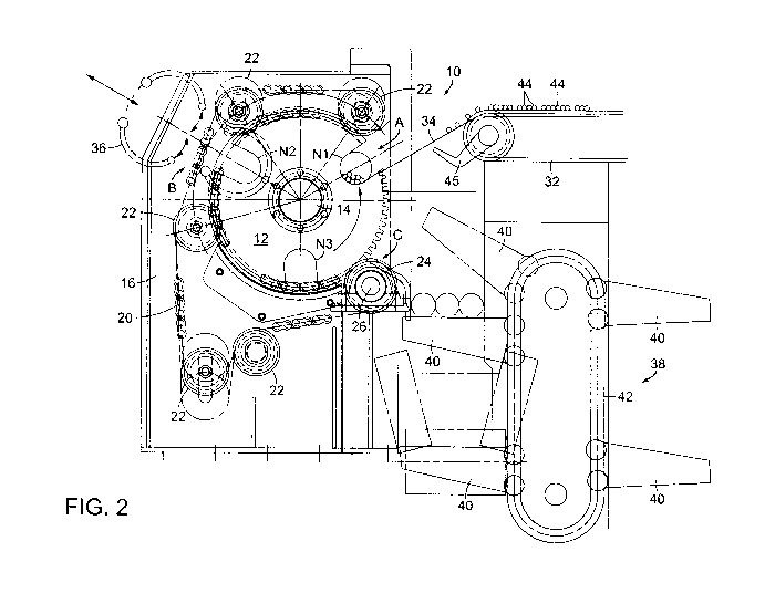
Figure 2 is an enlarged cross sectional view taken along line 2-2 of Figure 1;
Figure 3 is an enlarged cross sectional view taken along line 3-3 of Figure 2;
Figure 4 is a partial plan view of a drive chain; and
Figures 5A-5F are views similar to Figure 2 showing successive stages of
sequential bundling operations.
DETAILED DESCRIPTION
With reference initially to Figures 1 and 2, an apparatus for bundling bars is
shown at 10. The apparatus comprises an accumulator having a plurality of
wheels 12
spaced along and rotatable in unison about a horizontal axis "X". The wheels
are
fixed to a common central shaft 14 rotatably supported at appropriate
locations by
bearings carried on support stricturesl6.
The wheels 12 have mutually aligned peripheral notches N1-N3 separated by
peripheral toothed segments 18. The wheels 12 are driven for rotation about
axis X
by endless chains 20 partially wrapped around the wheels 12 in engagement with
the
toothed segments. The chains are guided by idler sprockets 22 and driven by
drive
sprockets 24. The drive sprockets 24 are carried on a, shaft 26 parallel to
axis X.
Shaft 26 is rotatably driven via a gear box 28 by motor 30.
As can best be seen in Figures 3 and 4, the chains 20 have three strands 20a,
20b, 20c. The central strands 20b engage the toothed segments 18 of the wheels
12,
and the outboard strands 20, 20, engage teeth on the sprockets 22, 24.
Again with reference to Figure 2, it will be understood that the chains 20 are
driven to rotatably index the wheels 12 about axis X to sequentially position
the
notches N -N3 at circumferentially spaced stations A, B, and C. At station A,
a bar
delivery conveyor 32 leads to a downwardly inclined ramp 34. At station B,
strapping
machines 36 are arranged at appropriate intervals between the wheels 12. A
bundle

CA 02797667 2012-10-26
WO 2011/139493 PCT/US2011/032085
collector 38 is arranged at station C. The bundle accumulator has elevator
arms 40
vertically adjustable by means of chains 42.
Figure 2 illustrates the bundling apparatus at the outset of a bundling
operation. Conveyor 32 is operating to deliver bars 44 down ramp 34 into
notches N
located at station A. At this stage, notches N2 and N3 empty. With reference
to
Figures 5A to 5F, subsequent stages in the bundling operation are as follows:
Figure 5A
A batch of bars has been accumulated at station A in the aligned notches N1,
and a stop 45 has been raised. to interrupt the further descent of bars down
ramp 34.
Figure 5l3
The wheels 12 have been rotatably indexed about axis X to position notches
N1 at a station B and to position notches J_` 3 at station A.
'ie-ure 5C
The strapping machines 36 are cycled to strap the batch of bars in notches i
into a bundle. The stop 45 has been lowered to allow the next batch of bars to
descend ramp 34 and to accumulate simultaneously in notches N3.
Figure 5D
The strapping machines 36 are withdrawn, the stop 45 is raised, and the
wheels 12 are again rotatably indexed to locate the batch of bars in notches
N3 at
station B in preparation for the next strapping operation. The previously
strapped
bundle is retained in notches `l by the chains 20. Notches N2 are positioned
at
station A in readiness to receive and accumulate the next batch of bars.
Figure 5E
The batch of bars in notches N3 are strapped into a bundle at station B while
the next batch of bars is simultaneously accumulating in notches N2 at station
A.
Figure 5F
The strapping machines 36 are withdrawn, and the stop 45 raised to again
interrupt delivery of bars to the accumulator. As the wheels 12 rotate back to
the
positions shown in Figure 2, a strapped bundle is delivered under gravity from
notches N, onto an elevator arm 40 of the bundle accumulator 38.
The above described sequence of bar accumulation, batch strapping and
bundle delivery may be operated continuously, with successive strapped bundles
being delivered to the bundle accumulator 38.
3

CA 02797667 2012-10-26
WO 2011/139493 PCT/US2011/032085
By simultaneously performing accumulation of bars into batches at station A
and the strapping; of batches into bundles at station B, an important time
savings is
achieved in the processing of successive bundles, thus advantageously
increasing
overall efficiency of the bundling operation.
4

Representative Drawing
A single figure which represents the drawing illustrating the invention.
Administrative Status

2024-08-01:As part of the Next Generation Patents (NGP) transition, the Canadian Patents Database (CPD) now contains a more detailed Event History, which replicates the Event Log of our new back-office solution.

Please note that "Inactive:" events refers to events no longer in use in our new back-office solution.

For a clearer understanding of the status of the application/patent presented on this page, the site Disclaimer , as well as the definitions for Patent , Event History , Maintenance Fee  and Payment History  should be consulted.

Event History

Description Date
Time Limit for Reversal Expired 2015-04-14
Application Not Reinstated by Deadline 2015-04-14
Deemed Abandoned - Failure to Respond to Maintenance Fee Notice 2014-04-14
Inactive: Cover page published 2013-01-07
Letter Sent 2012-12-27
Inactive: Notice - National entry - No RFE 2012-12-17
Application Received - PCT 2012-12-17
Inactive: First IPC assigned 2012-12-17
Inactive: IPC assigned 2012-12-17
Inactive: Single transfer 2012-11-16
National Entry Requirements Determined Compliant 2012-10-26
Application Published (Open to Public Inspection) 2011-11-10

Abandonment History

Abandonment Date Reason Reinstatement Date
2014-04-14

Maintenance Fee

The last payment was received on 2013-03-06

Note : If the full payment has not been received on or before the date indicated, a further fee may be required which may be one of the following

  • the reinstatement fee;
  • the late payment fee; or
  • additional fee to reverse deemed expiry.

Please refer to the CIPO Patent Fees web page to see all current fee amounts.

Fee History

Fee Type Anniversary Year Due Date Paid Date
Basic national fee - standard 2012-10-26
Registration of a document 2012-11-16
MF (application, 2nd anniv.) - standard 02 2013-04-12 2013-03-06
Owners on Record

Note: Records showing the ownership history in alphabetical order.

Current Owners on Record
SIEMENS INDUSTRY, INC.
Past Owners on Record
S. MARK SHORE
T. MICHAEL SHORE
XIANCHENG LU
Past Owners that do not appear in the "Owners on Record" listing will appear in other documentation within the application.
Documents

To view selected files, please enter reCAPTCHA code :


To view images, click a link in the Document Description column. To download the documents, select one or more checkboxes in the first column and then click the "Download Selected in PDF format (Zip Archive)" or the "Download Selected as Single PDF" button.

List of published and non-published patent-specific documents on the CPD .

If you have any difficulty accessing content, you can call the Client Service Centre at 1-866-997-1936 or send them an e-mail at CIPO Client Service Centre.


Document
Description 
Date
(yyyy-mm-dd) 
Number of pages   Size of Image (KB) 
Drawings 2012-10-26 9 625
Description 2012-10-26 4 215
Abstract 2012-10-26 2 84
Claims 2012-10-26 2 68
Representative drawing 2012-10-26 1 89
Cover Page 2013-01-07 2 79
Reminder of maintenance fee due 2012-12-17 1 113
Notice of National Entry 2012-12-17 1 206
Courtesy - Certificate of registration (related document(s)) 2012-12-27 1 126
Courtesy - Abandonment Letter (Maintenance Fee) 2014-06-09 1 172
PCT 2012-10-26 6 190