Note: Descriptions are shown in the official language in which they were submitted.
CA 02797706 2012-10-26
WO 2011/137199
PCT/US2011/034227
CONTROL OF A FLUID PUMP ASSEMBLY
This application is being filed on 28 April 2011, as a PCT
International Patent application in the name of Eaton Corporation, a U.S.
national
corporation, applicant for the designation of all countries except the U.S.,
and Philip
J. Dybing, a citizen of the U.S., applicant for the designation of the U.S.
only, and
=
claims priority to U.S. Patent Application Serial No. 12/770,261 filed on 29
April
2010.
BACKGROUND
[0001] Fluid systems used in various applications often have
requirements
that are variable. For example, fluid systems may require variable flow rates
and
variable fluid pressures. Load sensing pumps can be used to tailor the
operation of a
pump to meet the variable flow requirements of a given fluid system. A typical
load
sense pump uses flow and pressure feedbacks in the fluid system to adjust the
flow
requirements of the pump.
SUMMARY
[0002] An aspect of the present disclosure relates to a pump control
assembly. The pump control assembly includes a fluid pump assembly having a
fluid pump and a load sensing valve. The fluid pump includes a fluid inlet and
a
fluid outlet. The fluid pump includes a variable displacement mechanism. The
load
sensing valve is adapted to adjust the position of the variable displacement
mechanism. The load sensing valve includes a first end and an oppositely
disposed
second end. An actuator is in fluid communication with the fluid pump
assembly.
A position sensor monitors the position of the actuator. A ramping valve
provides
selective fluid communication between the fluid outlet of the fluid pump and
the
first end of the load sensing valve to adjust the position of the variable
displacement
mechanism. An electronic control unit is in electrical communication with the
position sensor and the ramping valve. The electronic control unit transmits
an
output current to the ramping valve in response to the position of the
actuator.
[0003] Another aspect of the present disclosure relates to a pump
control
assembly. The pump control assembly includes a fluid pump assembly. The fluid
1
CA 02797706 2012-10-26
WO 2011/137199
PCT/US2011/034227
pump assembly includes a fluid pump and a load sensing valve. The fluid pump
includes a fluid inlet and a fluid outlet. The fluid pump includes a variable
displacement mechanism that is movable between a neutral position and a first
position. The load sensing valve is adapted to adjust the position of the
variable
displacement mechanism. The load sensing valve has a first end and an
oppositely
disposed second end. An actuator is in fluid communication with the fluid pump
assembly. The actuator includes a housing having a first axial end and an
oppositely
disposed second axial end. The housing defines a bore. The actuator further
includes a piston disposed in the bore of the housing. A ramping valve
assembly
includes a ramping valve that is disposed in fluid communication with the
fluid
outlet of the fluid pump. The ramping valve is electronically actuated to
provide
fluid communication between the fluid outlet of the fluid pump and the first
end of
the load sensing valve when the piston of the actuator approaches one of the
first and
second axial ends so that the variable displacement mechanism is moved toward
the
neutral position.
[0004] Another aspect of the present disclosure relates to a method
for
actuating a pump control assembly. The method includes providing a pump
control
assembly having a fluid pump, a load sensing valve, an actuator and a ramping
valve. The fluid pump has a fluid inlet and a fluid outlet. The fluid pump
includes a
variable displacement mechanism. The load sensing valve is adapted to adjust
the
position of the variable displacement mechanism. The load sensing valve
includes a
first end and an oppositely disposed second end. The actuator is in fluid
communication with the fluid outlet of the fluid pump. The ramping valve
provides
selective fluid communication between the fluid outlet and the first end of
the load
sensing valve. A signal from a position sensor is received. The position
sensor is
adapted to monitor the position of the actuator. An output current is
transmitted to
the ramping valve when the actuator approaches a travel limit of the actuator
so that
the variable displacement mechanism is displaced toward a neutral position.
[0005] A variety of additional aspects will be set forth in the
description that
follows. These aspects can relate to individual features and to combinations
of
features. It is to be understood that both the foregoing general description
and the
following detailed description are exemplary and explanatory only and are not
restrictive of the broad concepts upon which the embodiments disclosed herein
are
based.
2
CA 02797706 2012-10-26
WO 2011/137199
PCT/US2011/034227
DRAWINGS
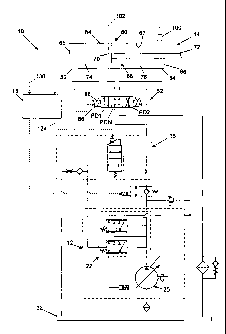
[0006] FIG. 1 is a schematic representation of a pump control assembly
having exemplary features of aspects in accordance with the principles of the
present
disclosure.
[0007] FIG. 2 is a schematic representation of a fluid pump assembly
suitable for use in the pump control assembly of FIG. 1.
[0008] FIG. 3 is a schematic representation of a ramping valve assembly
suitable for use in the pump control assembly of FIG. 1.
[0009] FIG. 4 is a representation of a method for operating the pump
control
assembly of FIG. 1.
[0010] FIG. 5 is a graphical representation of an exemplary profile of
an
electronic signal transmitted from an electronic control unit to the ramping
valve
assembly of FIG. 3.
DETAILED DESCRIPTION
[0011] Reference will now be made in detail to the exemplary aspects of
the
present disclosure that are illustrated in the accompanying drawings. Wherever
possible, the same reference numbers will be used throughout the drawings to
refer
to the same or like structure.
[0012] Referring now to FIG. 1, a pump control assembly 10 is shown.
The
pump control assembly 10 is adapted to control the output of a fluid pump
based on
a position of an actuator. In the subject embodiment, the pump control
assembly 10
is adapted to prevent spikes in fluid pressure when the actuator reaches its
travel
limit. In the depicted embodiment, of FIG. 1, the pump control assembly 10
includes a fluid pump assembly 12, an actuator assembly 14, a ramping valve
assembly 16 and an electronic control unit 18.
[0013] Referring now to FIGS. 1 and 2, the fluid pump assembly 12 will
be
described. The fluid pump assembly 12 includes a fluid pump 20 and a load
sensing
compensator valve assembly 22.
[0014] The fluid pump 20 includes a fluid inlet 24, a fluid outlet 26,
a drain
port 28 and a load sense port 30. The fluid inlet 24 of the fluid pump 20 is
in fluid
communication with a fluid reservoir 32. The fluid outlet 26 is in fluid
3
CA 02797706 2012-10-26
WO 2011/137199
PCT/US2011/034227
communication with the actuator assembly 16. The drain port 28 is in fluid
communication with the fluid reservoir 32.
[0015] The fluid pump 20 further includes a shaft 34. The shaft 34 is
coupled to a power source (e.g., an engine, electric motor, etc.) that rotates
the shaft
34. As the shaft 34 rotates, fluid is pumped from the fluid inlet 24 to the
fluid outlet
26.
[0016] The fluid pump 20 is a variable displacement fluid pump. As a=
variable displacement pump, the fluid pump 20 includes a variable displacement
mechanism 36. In the depicted embodiment, the fluid pump 20 is an axial piston
pump and the variable displacement mechanism 36 is a swash plate. The swash
plate 36 is movable between a neutral position and a full stroke position. In
the
neutral position, the displacement of the fluid pump 20 is about zero. At zero
displacement, no fluid passes through fluid pump 20 as the shaft 34 rotates.
In the
full stroke position, a maximum amount of fluid passes through the fluid pump
20 as
the shaft 34 rotates.
[0017] The fluid pump 20 includes a control piston 38 and a biasing
member
40. The control piston 38 and the biasing member 40 act against the swash
plate 36
to adjust the position of the swash plate 36. The control piston 38 is adapted
to
adjust the position of the swash plate 36 from the full stroke position to the
neutral
position. The control piston 38 is in selective fluid communication with the
fluid
outlet 26 of the fluid pump 20. The control piston 38 is in fluid
communication with
the load sensing compensator valve assembly 22.
[0018] The biasing member 40 is adapted to bias the fluid pump 20
toward
the full stroke position. The biasing member 40 includes a spring that biases
swash
plate 36 toward the full stroke position.
[0019] The load sensing compensator valve assembly 22 is adapted to
vary
the flow of fluid and the pressure of the fluid from the fluid pump 20 as the
flow and
pressure requirements of the system employing the fluid pump 20 vary. In the
depicted embodiment, the load sensing compensator valve assembly 22 includes a
load sense valve 42 and a pressure limiting compensator 44. In one embodiment,
the load sensing compensator valve assembly 22 is external to the fluid pump
20. In
another embodiment, the load sensing compensator valve assembly 22 is integral
to
the fluid pump 20.
4
CA 02797706 2012-10-26
WO 2011/137199
PCT/US2011/034227
[0020] The load sensing valve 42 provides selective fluid
communication
between the control piston 38 and either the drain port 28 or the fluid outlet
26 of the
fluid pump 20. In the depicted embodiment, the load sensing valve 42 is a
proportional two-position, three-way valve. In a first position Pl, the load
sensing
valve 42 provides fluid communication between the control piston 38 and the
drain
port 28 so that fluid acting against the control piston 38 is drained to the
fluid
reservoir 32 through the drain port 28. With the load sensing valve 42 in this
first
position Pl, the swash plate 36 is biased toward the full stroke position by
the
biasing member 40.
[0021] In a second position P2, the load sensing valve 42 provides
fluid
communication between the control piston 38 and the fluid outlet 26 so that
pressurized fluid acts against the control piston 38. With the load sensing
valve 42
in this second position P2, the control piston 38 acts against the biasing
member 40
to move the swash plate 36 toward the neutral position.
[0022] The load sensing valve 42 includes a first end 46 and an
oppositely
disposed second end 48. The first end 46 is in fluid communication with the
load
sense port 30. Fluid from the load sense port 30 acts against the first end 46
to
actuate the load sensing valve 42 to the first position. In the depicted
embodiment, a
light spring 50 also acts against the first end 46 of the load sensing valve
42 to bias
the load sensing valve 42 to the first position Pl. In one embodiment, the
combined
load against the first end 46 of the load sensing valve 42 is equal to the
pressure of
the fluid from the load sensing port 30 plus about 200 psi to about 400 psi.
[0023] The second end 48 of the load sensing valve 42 is in fluid
communication with the fluid outlet 26 of the fluid pump 20. When the fluid
pressure acting on the second end 48 is greater than the fluid pressure acting
on the
first end 46, the control piston 38 actuates the swash plate 36 in a direction
toward
the neutral position, thereby decreasing the amount of fluid displaced by the
fluid
pump 20.
[0024] The pressure limiting compensator 44 is a type of pressure
relieving
valve. In the depicted embodiment, the pressure limiting compensator 44 is a
proportional two-position, three-way valve. The pressure limiting compensator
44
includes a first end 52 and an oppositely disposed second end 54. A heavy
spring 56
acts against the first end 52 of the pressure limiting compensator 44 while
fluid from
the fluid outlet 26 acts against the second end 54.
CA 02797706 2012-10-26
WO 2011/137199
PCT/US2011/034227
[0025] The pressure limiting compensator 44 includes a first position
PC1
and a second position PC2. In the first position PC1, the pressure limiting
compensator 44 provides a fluid passage to the drain port 28. When the
pressure
limiting compensator 44 is in the first position PC1 and the load sensing
valve 42 is
in the first position Pl, fluid acting against the control piston 38 is
drained to the
fluid reservoir 32 through the drain port 28. With the pressure limiting
compensator
44 in this first position PC1 and the load sensing valve 42 in the first
position Pl, the
swash plate 36 is biased toward the full stroke position by the biasing member
40.
[0026] In the second position PC2, the pressure limiting compensator 44
provides fluid communication between the control piston 38 and the fluid
outlet 26
so that pressurized fluid acts against the control piston 38. With the
pressure
limiting compensator 44 in this second position PC2, the control piston 38
acts
against the biasing member 40 to move the swash plate 36 toward the neutral
position.
[0027] As fluid pressure in the fluid outlet 26 rises and approaches a
load
setting of the heavy spring 56, the pressure limiting compensator 44 shifts
toward
the second position PC2 allowing fluid to pass to the control piston 38. As
fluid acts
against the control piston 38, the position of the swash plate 36 is moved
toward the
neutral position. This movement continues until the amount of fluid at the
fluid
outlet 26 of the fluid pump 20 is low enough to maintain the system pressure
at the
load setting of the heavy spring 56 or until the fluid pump 20 is in the
neutral
position. In one embodiment, the heavy spring 56 provides a load setting of
about
2500 psi to about 3500 psi system pressure.
[0028] Referring now to FIG. 1, the actuator assembly 14 includes an
actuator 60 and a directional control valve 62. The actuator 60 can be a
linear
actuator (e.g., a cylinder, etc.) or a rotary actuator (e.g., a motor, etc.).
In the subject
embodiment, the actuator 60 is a linear actuator.
[0029] The actuator 60 includes a housing 64. The housing 64 includes a
first axial end 65 and an oppositely disposed second axial end 66.
[0030] The housing 64 defines a bore 67. A piston assembly 68 is
disposed
in the bore 67. The piston assembly 68 includes a piston 70 and a rod 72. The
bore
67 includes a first chamber 74 and a second chamber 76. The first chamber 74
is
disposed on a first side of the piston 70 while the second chamber 76 is
disposed on
an oppositely disposed second side of the piston 70.
6
CA 02797706 2012-10-26
WO 2011/137199
PCT/US2011/034227
[0031] The actuator 60 includes a first control port 82 and a second
control
port 84. The first control port 82 is in fluid communication with the first
chamber
74 while the second control port 84 is in fluid communication with the second
chamber 76.
[0032] The directional control valve 62 is in fluid communication with
the
actuator 60. In the depicted embodiment, the direction control valve 62 is a
three-
position, four-way valve. The direction control valve 62 includes a first
position
PD1, a second position PD2 and a closed center neutral position PDN.
[0033] In the first position, the direction control valve 62 provides
fluid
communication between the fluid pump 20 and the first control port 82 and
between
the second control port 84 and the fluid reservoir 32. In the depicted
embodiment,
the first position PD1 results in extension of the piston assembly 68 from the
housing 64. In the second position PD2, the direction control valve 62
provides
fluid communication between the fluid pump 20 and the second control port 84
and
between the first control port 82 and the fluid reservoir. In the depicted
embodiment, the second position PD2 results in retraction of the piston
assembly 68.
[0034] In the depicted embodiment, the directional control valve 62 is
actuated by a plurality of solenoid valves 86. A plurality of centering
springs 88 is
adapted to bias the directional control valve 62 to the neutral position PN1.
[0035] The pump control assembly 10 further includes a position sensor
100.
The position sensor 100 is adapted to provide data to the electronic control
unit 18
regarding the position of the actuator 60. The position sensor 100 can be an
analog
sensor or a digital sensor.
[0036] In one embodiment, the position sensor 100 is adapted to
transmit a
signal 102 to the electronic control unit 18 when the piston 70 approaches the
first
and/or second axial ends 65, 66 of the housing 64. As will be described in
more
detail subsequently, the electronic control unit 18 uses the data from the
position
sensor 100 to control the ramping valve assembly 16.
[0037] Referring now to FIGS. 1 and 3, the ramping valve assembly 16
will
be described. The ramping valve assembly 16 is adapted to control the fluid
output
of the fluid pump 20 based on the position of the actuator 60 of the actuator
assembly 14. The ramping valve assembly 16 includes a ramping valve 110 and an
orifice 112.
7
CA 02797706 2012-10-26
WO 2011/137199
PCT/US2011/034227
[0038] In the depicted embodiment, the ramping valve assembly 16
includes
an inlet 114, an outlet 116, a load sense passage 118 and a drain passage 120.
The
inlet 114 is in fluid communication with the fluid outlet 26 of the fluid pump
20.
The outlet 116 is in fluid communication with the directional control valve 62
of the
actuator assembly 14. The load sense passage 118 is in fluid communication
with
the load sensing compensator valve assembly 22. The drain passage 120 is in
fluid
communication with the fluid reservoir 32.
[0039] The ramping valve 110 provides selective fluid communication
between the fluid outlet 26 of the fluid pump 20 and the load sense port 30 of
the
fluid pump 20. In the depicted embodiment, the ramping valve 110 is a
proportional
two-position, two-way solenoid valve. In a first position PR1, the ramping
valve
110 blocks fluid communication to the load sense port 30. In a second position
PR2,
the ramping valve 110 provides full fluid communication to the load sense port
30.
A spring 121 biases the ramping valve 110 to the first position PR1.
[0040] The ramping valve 110 is actuated by a solenoid 122 in response
to
an output current 124 from the electronic control unit 18 (shown in FIG. 1).
The
output current 124 is sent from the electronic control unit 18 in response to
the
signal 102 from the position sensor 100. As the ramping valve 110 is a
proportional
valve, the flow of fluid through the ramping valve 110 is proportional to the
output
current 124 received by the solenoid 122 from the electronic control unit 18.
Therefore, the flow of fluid to the load sense port 30 is proportional to the
output
current 124.
[0041] As the load sense port 30 is in fluid communication with the
first end
46 of the load sensing valve 42 of the fluid pump assembly 12 and as the load
sensing valve 42 is used to adjust the position of the swash plate 36, which
controls
the flow of fluid from the fluid pump 20, the flow of fluid from the fluid
pump 20 is
proportional to the output current 124. As will be described in greater detail
subsequently, the output current 124 can be programmed to prevent spikes in
fluid
pressure when the piston 70 of the actuator assembly 14 reaches one of the
first and
second axial ends 65, 66 of the housing 64.
[0042] In the depicted embodiment, the ramping valve 110 also includes
an
actuation member 130 that is adapted for manual actuation. The actuation
member
130 allows for a manual override of the solenoid 122.
8
CA 02797706 2012-10-26
WO 2011/137199
PCT/US2011/034227
[0043] The orifice 112 provides fluid communication between the load
sense
passage 118 and the drain passage 120. When the ramping valve 110 is in the
first
position PR1, fluid acting against the first end 46 of the load sensing valve
42 of the
fluid pump assembly 12 is drained to the fluid reservoir 32 through the
orifice 112.
When the ramping valve 110 is actuated so that fluid passes from the inlet 114
to the
load sense passage 118, the orifice 112 becomes saturated. With the orifice
112
saturated, fluid is directed from the ramping valve 110 to the first end 46 of
the load
sensing valve 42.
[0044] Referring now to FIGS. 1-4, a method 200 of operating the pump
control assembly 10 will be described. In step 202, the electronic control
unit 18
receives an input signal 130. In one embodiment, the input signal 130 is
provided
by an operator using an input device (e.g., joystick, steering wheel, etc.)
that is
adapted to control a function of a work vehicle (e.g., refuse truck, skid
steer loader,
backhoe, excavator, tractor, etc.).
[0045] In response to the input signal 130, the electronic control
unit 18
sends the output current 124 to the solenoid 122 of the ramping valve 110 in
step
204. The output current 124 is adapted to move the ramping valve 110 from the
first
position PR1 to the second position PR2 (i.e., to open the ramping valve 110).
[0046] Referring now to FIG. 5, a graphical representation of an
exemplary
profile of the output current 124 is shown. The profile of the output current
124
includes a ramp-up portion 132, a sustain portion 134 and a ramp-down portion
136.
In the ramp-up portion 132, the magnitude of the output current 124 increases
over a
predetermined time t so that the ramping valve 110 is gradually actuated to
the
second position PR2 (i.e., the ramping valve 110 opens). In the ramp-up
portion
132, the output current 124 is at zero power at an initial time to and
increases to full
power at time t1. In one embodiment, the time between the initial time to and
time t1
is less than about 500 ms. In another embodiment, the time between the initial
time
to and time t1 is in a range of about 200 ms to about 500 ms.
[0047] In the ramp-down portion 136, the magnitude of the output
current
124 decreases over a predetermined time t so that the ramping valve 110 is
gradually
actuated to the first position PR1 (i.e., the ramping valve 110 closes). In
the ramp-
down portion 136, the output current 124 is at a given power at time t2 and
decreases
to zero power at t3. In one embodiment, the time between the time t2 and the
time t3
is less than about 1000 ms. In another embodiment, the time between the time
t2 and
9
CA 02797706 2016-04-21
the time t3 is in a range of about 200 ms to about 1000 ms. In another
embodiment, the
time between the time t2 and the time t3 is equal to the time between the
initial time to and
time t.
[0048] Referring now to FIG. 1 -5, when the input signal 130 is received
by the
electronic control unit 18, the ramp-up portion 132 of the output current 124
is
transmitted to the solenoid 122 in step 204. The actuation of the ramping
valve 110 to the
second position PR2 causes fluid from the fluid outlet 26 of the fluid pump 20
to be
communicated to the first end 46 of the load sensing valve 42. The fluid at
the first end
46 of the load sensing valve 42 gradually shifts the load sensing valve 42 to
the first
position PI, which gradually increases the displacement of the fluid pump 20,
[0049] In step 206, the electronic control unit 18 receives the signal 102
from
the position sensor 100 that indicates that the piston 70 is adjacent to one
of the first and
second axial ends 65, 66 of the housing 64 of the actuator 14. In response to
the signal
102, the ramp-down portion of the output current 124 is transmitted to the
solenoid 122
of the ramping valve 110 in step 208.
[0050] The decreasing output current 124 in the ramp-down portion 136
causes
that the ramping valve 110 to be gradually actuated from the second position
PR2 to the
first position PRI. As the ramping valve 110 is gradually actuated to the
first position
PRI, fluid acting on the first end 46 of the load sensing valve 42 is
communicated to the
fluid reservoir 32 through the orifice 112. As fluid acting on the first end
46 of the load
sensing valve 42 is drained to the fluid reservoir 32, the displacement of the
fluid pump
20 decreases. The decreasing displacement of the fluid pump 20 results in a
decreased
flow rate to the actuator assembly 14 through the fluid pump 20. In one
embodiment, the
swash plate 36 of the fluid pump 20 is adapted to be disposed in the neutral
position as
the piston 70 reaches one of the first and second axial end 65, 66 of the
housing 64 of the
actuator assembly 14.
[0051] The gradual decrease of the variable displacement mechanism 36 of
the
fluid pump 20 as the actuator 60 reaches its travel limit reduces or prevents
pressure
spikes in the fluid of the pump control assembly 10. This reduction in
pressure spikes
makes the operation of the pump control assembly 10 smoother.
[0052] Various modifications and alterations of this disclosure will
become
apparent to those skilled in the art without departing from this
CA 02797706 2012-10-26
WO 2011/137199
PCT/US2011/034227
disclosure, and it should be understood that the scope of this disclosure is
not to be
unduly limited to the illustrative embodiments set forth herein.
11