Note: Descriptions are shown in the official language in which they were submitted.
CA 02798287 2013-11-28
Harvester for Potatoes, Beets and other Root Crops
The invention concerns a harvester for potatoes, beets and other root crops,
in
particular in the form of a bunker harvester.
For harvesting root crops in the form of potatoes, beets and other root crops,
potato
harvesters that are pulled by tractors or self-propelled harvesters have been
known for a
long time. In this connection, so-called transfer harvesters are used in which
the
harvested root crops that has been separated from adhering parts are
transferred by a
conveying device that is substantially oriented transversely to the travel
direction of the
harvester onto a collecting vehicle driving alongside the harvester. In
addition to these
transfer harvesters that are associated directly with the harvesting process,
harvesters
are also known that are referred to as bunker harvesters in which the
harvested crops
are collected in variably embodied receiving spaces of at least one bunker so
that only
after completion of a harvesting phase with filling of this bunker a later
transfer process
is required. Such harvesters with intermediate bunker are known in various
embodiments on the market (company brochure "Produktprogramm", No.
L01.1002.DE/12/10/2500 of the company Grimme Landmaschinenfabrik GmbH & Co.
KG, 49401 Damme, Germany).
In a bunker construction in accordance with DE 39 00 573 Al, the root crops is
moved in
the area of a sidewall that is acting as a glide plate to a conveyer at the
bottom. From
here, the generally known discharge of the root crop is realized by means of a
discharge
conveyor that forms the second sidewall and is a second unit of the complex
discharge
system.
The invention concerns the problem to configure a harvester for various root
crops such
that the bunker provided for collecting the harvested crop enables with
reduced technical
expenditure an optimal distribution of the harvested crop in the receiving
space and such
that the subsequent emptying of the receiving space can be performed
substantially
- 1 -
CA 02798287 2013-11-28
without damage to and without loss of harvested crop.
According to an aspect of the present invention, there is provided a harvester
for
potatoes, beets and other root crops, in particular in the form of a self-
propelled or
pulled bunker harvester, that comprises an intermediate or transfer bunker
receiving
harvested root crop after a cleaning phase, wherein from its receiving space
the
harvested root crop can be discharged by means of a conveying device that
forms at
least partially in the bunker a floor conveyer, comprises a lateral transfer
module and
can be oriented substantially transversely to the travel direction of the
harvester,
characterized in that the conveying device interacts with a wall-type movable
support
structure at least in the area of a longitudinal side of the receiving space
that is facing
away from the lateral transfer module.
According to another aspect of the present invention, there can be provided
the
harvester described herein, characterized in that the receiving space of the
bunker is
delimited at least at times during filling and/or discharging by the support
structure
that is essentially vertically extending.
According to another aspect of the present invention, there can be provided
the
harvester described herein, the support structure has dimensions that make
obsolete
the additional arrangement of a substantially vertical longitudinal sidewall.
According to another aspect of the present invention, there can be provided
the
harvester described herein, characterized in that the support structure is
provided
with movement parts that at least when the conveying device is active assist
its
respective conveying direction.
According to another aspect of the present invention, there can be provided
the
harvester described herein, characterized in that the support structure in the
receiving
space forms a guiding contour for the root crop in such a way that in a return
phase
following a discharge phase in the area of the conveying device the residual
quantities of root crop positioned thereon can be moved into a collecting zone
of the
receiving space.
- 2 -
CA 02798287 2013-11-28
According to another aspect of the present invention, there can be provided
the
harvester described herein, characterized in that the collecting zone forms a
support
contour in front of the vertical support structure.
According to another aspect of the present invention, there can be provided
the
harvester described herein, characterized in that the support structure is
formed
immediately as a movable section of the conveying device.
According to another aspect of the present invention, there can be provided
the
harvester described herein, characterized in that the movable support
structure in the
area of the conveying device is connected with the floor conveyer and the
transfer
module.
According to another aspect of the present invention, there can be provided
the
harvester described herein, characterized in that the conveying device is
provided
with a belt conveyor that is driven in circulation and passes through the
movable
section of the support structure.
According to another aspect of the present invention, there can be provided
the
harvester described herein, characterized in that the belt conveyor by means
of
deflecting elements, respectively, forms the section of the vertical support
structure.
According to another aspect of the present invention, there can be provided
the
harvester described herein, characterized in that the belt conveyor in the
area of the
support structure has two conveying shafts as deflecting elements that are
supported
one above the other on vertical bars.
According to another aspect of the present invention, there can be provided
the
harvester described herein, characterized in that the conveyor shafts are
drivable in
the area of the support structure.
- 2a -
=
CA 02798287 2013-11-28
According to another aspect of the present invention, there can be provided
the
harvester described herein, characterized in that the conveyor shafts are
adjustable
with respect to their spacing to each other.
According to another aspect of the present invention, there can be provided
the
harvester described herein, characterized in that the support structure is
formed as a
module that is active independent of the conveying device.
According to another aspect of the present invention, there can be provided
the
harvester described herein, characterized in that the wall-type support
structure is
pivotable or foldable into variable positions of use.
According to another aspect of the present invention, there can be provided
the
harvester described herein, characterized in that the wall-type support
structure has
movable sections.
According to another aspect of the present invention, there can be provided
the
harvester described herein, characterized in that the support structure is
movable into
a position of use which is in a common plane with the floor conveyer or into a
position
tilted relative thereto.
According to another aspect of the present invention, there can be provided
the
harvester described herein, characterized in that in the area of one or both
transverse
sides of the receiving space at least one movable support structure is
provided,
respectively.
According to another aspect of the present invention, there is provided a
harvester for
potatoes, beets and other root crops the harvester comprising:
an intermediate or transfer bunker receiving harvested root crop after a
cleaning phase, the bunker comprising a receiving space; and
a conveying device for discharging the harvested root crop from the receiving
space, the conveying device forming a floor conveyor at least partially in the
bunker,
- 2b -
CA 02798287 2013-11-28
the conveying device comprising a lateral transfer module and being oriented
substantially transversely to a travel direction of the harvester,
wherein the conveying device interacts with a wall-type movable support
structure at least in an area of a longitudinal side of the receiving space
that is facing
away from the lateral transfer module.
A harvester for root crop in the form of a self-propelled or pulled bunker
harvester is
provided with a device that is referred to as intermediate or transfer bunker
from which
the harvested root crop is discharged after a collecting phase by means of a
conveying
device. The concept according to the invention of this bunker construction
provides that
the bunker construction at least in the area of a longitudinal side of the
receiving space
that is facing away from the lateral transfer module is provided with a wall-
type support
structure that can be aligned and moved. The latter can interact in a
collecting phase, in
an intermediate phase and/or a discharge phase with a conveying device and
improve
.. the utilization conditions of the bunker in this way.
This support structure can be provided in addition to a longitudinal sidewall
of the bunker
that is usually provided for delimiting the receiving space. Advantageously,
the
construction is however such that the wall-type support structure that is
acting because
of its movability as a multifunctional device is integrated into the bunker
construction or
into its receiving space with dimensions that make a longitudinal sidewall
obsolete.
With this support structure that is substantially vertically aligned relative
to the bottom of
the receiving space it is achieved that the receiving space of the bunker at
least at times
during filling, storing and/or discharging is delimited by an active component
module that
can have a "controlling" effect on the collected harvested crop. In the
filling phase of
the receiving space, the support structure that is configured as a movable
section can be
displaced in addition to providing its substantially static support function
such that the
harvested crop, that can be optimally supported on the wall-type structure and
can be
stacked up to the desired filling level, is also exposed to a targeted
movement within the
receiving space in order to improve, for example, the filling condition.
- 2c -
CA 02798287 2012-12-05
During a subsequent discharge phase by means of the conveying device, the
support
structure configured as a movable section can enhance a targeted displacement
of the
harvested crop so that it is gently transferred onto the floor conveyor of the
bunker and
by means of the lateral transfer module of the conveying device is transferred
to the
transport vehicle that is adjacent to the harvester.
In accordance with the size ratios of the bunker and the receiving container
of the
transport vehicle, it may be required that upon complete filling thereof
already before
complete discharge of the receiving space the transfer process is to be
interrupted and
then in the area of the conveying device, or of the floor conveyor and the
transfer
module, a "residual quantity" of root crop or similar harvested crop is
remaining. In
particular for avoiding crop loss as harvesting is continued, this harvested
crop that is
suitable for a later transport must be returned into the receiving space in
order to avoid
an undesirable discharge of harvested crop onto the field. For this purpose,
the
discharge stroke of the conveying device that has been effective last can be
adjusted to
the opposite conveying direction so that the residual quantity that is still
in the conveying
area can be returned into the receiving space. During this return phase, the
"movable"
support structure can be used particularly efficiently in such a way that in
the area in
front of this wall-type vertical area of the support structure the residual
quantity of the
harvested crop can be held in a depression-like collecting zone without
damaging the
crop and thereby can be stored until the next emptying process takes place.
The support structure forms thus a functional unit which is provided with
movable parts
that, at least in case of an active conveying device, assist in its conveying
direction so
that the afore described conveying actions can be achieved in an optimal way.
The
movable support structure in this context can extend within the receiving
space with
substantially any guiding contour so that in the discharge phase as well as in
the
retaining phase the harvested crop can be influenced in an optimal way by the
movable
sections of the support structure. In this connection, it is provided that the
support
structure can extend into the region of the conveying device and therefore the
movable
- 3 -
Lit. TRL of DE102011120377.3 - First Named Inventor: K. Kalverkamp -Assignee:
Gnmme Landmaschinenfabrik
CA 02798287 2012-12-05
sections with the area of the floor conveyor and the transfer module interact
as a
compact controllable conveying unit.
For a simple realization of this controllable concept, in an expedient
embodiment it is
provided that the conveying device is provided with a generally known belt
conveyor. It
can be driven in circulation in an embodiment "extended" about the support
structure in
such a way that the conveying run of this belt conveyor defines the movable
section of
the support structure. This "extended" belt conveyor can form with minimal
expenditure
variable predeterminable sections of the particularly vertical area of the
support structure
wherein deflection elements determine the course. In this connection, with at
least one
central and/or additional belt drive also these sections of the support
structure are
engaged and the movement directions that are provided respectively can be set
optimally by means of a control.
In an expedient embodiment, it is provided that the belt conveyor in the area
of the
support structure has two conveyor shafts as deflection elements that are
supported on
top of each other at vertical bars, wherein these conveyor shafts can be
configured also
as drivable elements. The conveyor shafts are adjustable with respect to their
vertical
spacing so that the entire support structure is provided with optimal
conditions for the
circulating sections of the conveying device and the belt conveyor.
In addition to this embodiment of the system, integrated in the conveying
device with the
floor conveyor and transfer module, it is conceivable that the support
structure is
embodied however as a module that is acting substantially independent of the
conveying device. This support structure that can be defined in the form of an
independent vertical conveyor belt, roller belt or similar conveying device is
advantageously arranged in the area of the longitudinal sidewall that defines
the bunker.
This independently movable support structure can be switched on as needed
synchronously with the floor conveyor or the transfer module in any operating
phase of
the conveying device.
- 4 -
Lit. TRL of 0E102011120377.3 - First Named Inventor: K. Kalverkamp -Assignee:
Grimme Landmaschinenfabrik
Also, it is provided that the wall-type support structure, in the form of the
belt conveyor or
the independent module, forms a system that is connected to the bunker
construction so
as to be pivotable or foldable relative to the receiving space into variable
positions of
use. In this connection, the wall-type support structure can also be formed
with
displaceable, foldable, and/or pivotable sections so that wall areas, for
example, like an
overhang, can delimit the upper area of the receiving space.
In an expedient embodiment it is provided that the support structure is
moveable into
positions of use that are extending in the same plane as the floor conveyor or
are tilted
from this position. In this connection, for example a folding movement of the
support
structure can be provided that is directed from the receiving space outwardly.
In this
way, a discharge process is also conceivable at the longitudinal side of the
harvester
that is opposite the transfer module and useable, for example, in case of
"emergency
emptying" or the support structure is useable for transfer of residual
quantities of the
harvested crop in outwardly folded position.
In expanding on the afore described concept, it is conceivable to mount the
support
structure in the bunker at variable locations and to provide this system also
in the area of
one or both transverse sides of the receiving space. In this way, in these
areas by
.. movable wall-type parts or sections a support action of the respective
conveying process
is possible also and the respective collecting or transfer phase of such
transfer bunkers
can be further optimized.
In one aspect, there is provided a harvester for potatoes, beets and other
root crops,
.. the harvester comprising: a transfer bunker provided with a receiving space
in which
harvested root crop is received in a filling phase, wherein the receiving
space is
delimited by a bottom, two opposed end walls, and at least one longitudinal
wall
connected to the two end walls; a conveying device oriented substantially
transversely to a travel direction of the harvester and operative in a first
conveying
direction in a discharge phase and in a second opposite conveying direction in
a
- 5 -
CA 2798287 2018-08-20
return phase; wherein the conveying device comprises a floor conveyer arranged
in
the transfer bunker and forming the bottom of the receiving space; wherein the
conveying device further comprises a lateral transfer module connected to a
first end
of the floor conveyor and comprising a discharge end remote from the floor
conveyor; wherein the conveying device further comprises a wall-type moveable
support structure that is connected to a second end of the floor conveyer and
forms
the at least one longitudinal wall of the receiving space opposite the lateral
transfer
module; wherein the wall-type movable support structure, the floor conveyor,
and the
lateral transfer module together form a compact transport unit comprising a
.. continuous belt conveyor extending across the wall-type movable support
structure,
the floor conveyor, and the lateral transfer module to the discharge end and
from the
discharge end back to the wall-type moveable support structure; wherein, in
the
discharge phase, the continuous belt conveyor directly moves the harvested
root
crop out of the receiving space across the lateral transfer module to the
discharge
end and directly discharges the harvested root crop via the lateral transfer
module
and the discharge end into a transport vehicle in the first conveying
direction;
wherein the wall-type movable support structure is provided with moveable
parts
that, at least when the conveying device is active, assist in moving the
harvested
root crop in the first conveying direction out of the receiving space or in
the second
opposite conveying direction back into the receiving space; wherein the wall-
type
movable support structure forms a curved guiding contour for the harvested
root
crop in the receiving space and wherein the receiving space comprises a
collecting
zone immediately adjacent to the curved guiding contour of the wall-type
moveable
support structure such that, in the return phase following the discharge
phase,
residual quantities of the harvested root crop positioned on the continuous
belt
conveyor are moved in the second opposite conveying direction against the
curved
guiding contour and the curved guiding contour subjects the harvested root
crop to a
rolling movement in a direction away from the wall-type moveable support
structure
into the collecting zone of the receiving space.
- 5a -
CA 2798287 2018-08-20
Further details and advantageous embodiments of the invention result from the
following
description that shows an embodiments of the harvester according to the
invention with
improved bunker. In the drawings, it is shown in:
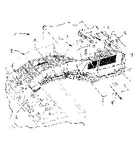
Fig. 1 a perspective detail illustration of a harvester in the area of a
transfer
bunker in a transfer phase;
Fig. 2 a cross-section illustration according to line II-II in Fig. 1;
- 5b -
CA 2798287 2018-08-20
CA 02798287 2012-12-05
Fig. 3 a sectioned perspective illustration similar to Fig. 2 in a
return conveying
phase in the area of the bunker; and
Fig, 4 a sectioned perspective illustration similar to Fig. 3 with
harvested crop in
the area of the receiving space.
In Fig. 1, in a schematic perspective illustration a harvester for potatoes,
beets or similar
crops 2 is illustrated and referenced by 1. This harvester 1 can be
particularly in the
form of a self-propelled or pulled bunker harvester that has an intermediate
or transfer
bunker 3 for receiving a root crop 2 after a cleaning phase (not illustrated).
The root
crop 2 is conveyed by means of a conveying device 4 into a receiving space 5
and is
stored therein at least at times during a harvesting cycle of the harvester 1.
From this
receiving space 5, the root crop 2 is discharged by means of a conveying
device 8 that
forms at least partially in the bunker a floor conveyor 6, is provided with a
lateral transfer
module 7 and extends substantially transverse to the travel direction F of the
harvester 1
(arrow A, Fig. 1).
The concept according to the invention of the harvester 1 provides that the
harvester in
the area of its bunker 3 interacting with the conveying device 8 is provided
with a
wall-type movable support structure 9 at least in the area of a longitudinal
side L of the
receiving space 5 that is facing away from the lateral transfer module 7. In
this way, it
is achieved that the receiving space 5 of the bunker 3 at least at times
during filling
(arrow D, Fig. 1) and/or discharge (arrow A) can be delimited by the
substantially
vertically extending support structure 9. This support structure 9 can be
provided in
addition to a sidewall (not illustrated) that can be positioned in the area of
the
longitudinal side L; advantageously, it is however provided that the support
structure 9
has dimensions H, B (Fig. 3) that make obsolete the additional arrangement of
a
sidewall.
The system with the movable support structure 9 is designed such that this
construction
- 6 -
Lit. TRL of DE102011120377.3 - First Named Inventor: K. Kalverkamp - Assignee:
Grimme Landmaschinenfabrik
CA 02798287 2012-12-05
has integrated therein movement parts, generally identified by 10, and with
these parts
10, at least upon activated conveying device 8, the respective crop stream
movements
can be assisted thereby in the respective conveying directions A or A'.
When looking at Fig. 1 through Fig. 4, it is apparent that the support
structure 9 in the
rim area of the receiving space 5 is effective in the manner of a guide
contour for the
root crop 2', In particular, in a return phase (arrow A', Fig. 4) following a
discharge
phase (arrow A, Fig. 1) reverse conveying conditions are required in order to
move
residual quantities of root crop 2' (Fig. 3) that are still positioned in the
area of the
conveying device 8 to a collecting zone Z of the receiving space 5. From the
illustration
according to Fig. 4 it is apparent that the collecting zone Z is formed
immediately in front
of the vertical support structure 9 and the residual quantity of the root crop
2' is optimally
stored here.
Upon return movement of the root crop 2' (Fig. 3 and Fig. 4), the crop is
optimally guided
along a curved contour S by the support structure 9 wherein a rolling movement
that is
indicated by the arrow R in the area S occurs such that damage of the
harvested crop 2'
as well as jamming of the harvested crop are prevented due to a substantially
angle-free
and edge-free configuration of this collecting zone Z.
An advantageous constructive configuration of the support structure 9 is
achieved
according to the invention in that the support structure 9 is configured
immediately as a
movable section of the conveying device 8 and the latter is then substantially
extending
monolithically below the root crop 2, 2'. In this connection, it is provided
that the
movable support structure 5 is connected immediately with the floor conveyor 6
and the
transfer module 7 so that in this way a compact transport unit is provided.
The representations according to Figs. 1 through 4 illustrate clearly this
embodiment of
the system wherein the conveying device 8 is provided with a belt conveyor 12
that is
driven in circulation and moves through the moveable section of the support
structure 9.
In the simplest embodiment the belt conveyor 12 is designed such that by means
of
- 7 -
Lit. TRL of DE102011120377.3 - First Named Inventor: K. Kalverkamp - Assignee:
Grimme Landmaschinenfabrik
CA 02798287 2012-12-05
deflecting elements 13, 14 that are arranged above each other the movable
section of
the vertical support structure 9 is defined. These deflection elements 13, 14
are
expediently formed by two conveying shafts 17, 18 that are supported one above
the
other at two vertical bars 15, 16.
It is conceivable in this connection that additionally to the drive 11 in the
area of the
conveying device 8 also one or two of the conveying shafts 17, 18 are provided
as
driven components. The construction provides that the conveying shafts 17, 18
are
adjustable by means of an adjusting element 19 that is provided in the area of
the
vertical bars 15, 16. In this way, the conveyor shafts 17, 18 can be adjusted
relative to
each other with regard to their vertical spacing (height H).
A further embodiment of the support structure 9 provided for the harvested
machine 1 is
that it is configured as a module (not illustrated) that is acting
independently of the
conveying device 8. Conceivable is in this connection that the support
structure 9 is
provided with a separate drive and that, in contrast to the illustrated
embodiment, also
independent adjustments in the area of the independent support structure 9 can
be
realized.
In supplementing the illustrated embodiment according to Figs. 1 to 4 or the
independent
support structure, it is also provided that the respective wall-type movable
system can
be embodied so as to be pivotable or foldable into variable positions of use.
Fig. 4
indicates with respective angle positions W, W', W" the conceivable pivot
positions of
the support structure 9. In this context, the support structure 9 can be
pivoted into a
position of use W' in which it is in a common plane with the floor conveyor 6
so that
already in this position a discharge of a residual quantity of root crop 2' is
possible (as
the conveyor 12 is running in the direction A'). This conceivable discharge,
in a
direction toward the side of the harvester that is facing away from the
transfer module 7,
is also conceivable in the respective positions W and W" of the support
structure 9.
Also, the afore described folding construction can be designed such that the
wall-type
- 8 -
Lit. TRL of DE102011120377.3 - First Named Inventor: K. Kalverkamp - Assignee:
Grimme Landmaschinenfabrik
CA 02798287 2012-12-05
support structure 9 has foldable sections only along its contour so that for
example the
upper rim area of the support structure 9 can be pivoted toward the receiving
space 5
and that therefore in this area a protective position acting like an overhang
is defined
that prevents escape of root crop 2'.
In a constructive further development of the afore described embodiment, a
harvester 1
with a bunker 3 is also conceivable in which the movable support structure 9
is arranged
in the area of one or both transverse sides 20, 21 of the receiving space 5
(not
illustrated) and the loading and discharging system of the bunker 3 can be
adjusted in
this way to further application situations, for example, change of root crops
with
changing conveying properties.
- 9 -
Lit. TRL of DE102011120377.3 - First Named Inventor: K. Kalverkamp - Assignee:
Grimme Landmaschinenfabrik