Note: Descriptions are shown in the official language in which they were submitted.
CA 02798768 2012-11-06
WO 2011/149501 PCT/US2011/000456
BOTTLE CAP FOR DISPERSING POWDERED SUPPLEMENT IN
SITU
BACKGROUND OF THE INVENTION
Cross Reference To Related Application(s)
[00011 This application claims priority from U.S. Patent Application Serial
Nos. 12/789,861, filed 28 May,
2010, and 12/983,813, filed 3 January, 2011, which are incorporated by
reference herein.
Addition of powdered supplements to a beverage container is becoming
increasingly popular. For
example, powdered supplements may be stored in an assembly which is fitted to
the neck of the container, to
release the supplement into a container of water, to be consumed by the user.
The assemblies can be expensive
to manufacture, and typically are designed to fit a specific container size.
SUMMARY OF THE INVENTION
[0002] In one embodiment, there is a dispensing cap system for dispensing a
supplement material through a
bottle neck opening and into the bottle. The system may include the cap system
along with the bottle, or just
the cap system. The system may also be combined with supplement stored therein
or without supplement
therein to be filled later by a user.
[0003] An exemplary embodiment includes the cap member, which is configured
with circumferentially
arranged fingers at a lower end for connection to beverage bottle necks of
different sizes, e.g., by engaging
threads on the bottle neck. A seal member preferably of rubber is arranged to
provide a liquid seal against the
bottle's mouth or neck opening, and to fit inside the member. The cap member
also has a storage member
connected to it, and/or forms or is part of a storage compartment, where the
supplement may be kept until use.
[0004] The cap system also includes a nipple for drinking liquid from the
bottle, the nipple being of similar
configuration to a standard water bottle or sports bottle nipple. There is
also a valve member, preferably
cylindrical and hollow, having an upper portion preferably inside the nipple,
and a lower portion with an
opening or openings for communicating the storage compartment and thus the
supplement with contents of the
bottle. The valve passes through the storage member or compartment which is
positioned around the valve,
and is configured for movement between a storage position and a dispensing
position, in which passage is
permitted of the supplement material from the storage member into the bottle
for mixing with the bottle's
contents. The valve is preferably normally closed, i.e., normally in the
storage position, and preferably actuated
by pressing down on the nipple until the valve's opening or openings are
registered with the storage
compartment, i.e., the dispensing position. The bottle may then be shaken to
mix the liquid and supplement,
and then the user may move the nipple fully upward to a drinking position.
1
CA 02798768 2012-11-06
WO 2011/149501 PCT/US2011/000456
BRIEF DESCRIPTION OF THE DRAWINGS
[0005] Features and advantages of the disclosure will readily be appreciated
by persons skilled in the art from
the following detailed description when read in conjunction with the drawing
wherein:
[0006] FIGS. lA-1C are exploded views of an exemplary embodiment of a bottle
cap dispensing system.
[0007] FIG. 2 is a cutaway view of an exemplary dispensing cap system as
installed on a bottle, with the
system in a filled state.
[0008] FIG. 3 is a cutaway view similar to FIG. 2, but with the valve member
in a dispensing state or position.
[0009] FIG. 4 is a cutaway view similar to FIG. 3, but with the cap nipple
pulled up and in an open state
relative to the valve member.
[0010] FIG. 5 is a cutaway view of a bottle of a large neck opening size in
relation to the bottle shown in FIG.
2, with an exemplary embodiment of the cap system installed on the bottle
neck.
[0011 ] FIG. 6 is an exploded view of an alternate embodiment of a dispensing
cap bottle cap dispensing
system.
[0012] FIG. 7 is a cutaway view of the alternate embodiment of FIG. 6 in an
assembled condition.
[0013] FIGS. 8, 9 and 10 are cutaway views of the alternate embodiment of FIG.
6, shown in an engaged
position on three exemplary bottle types.
[0014] FIG. 11 is a cutaway or sectional view of a further embodiment of the
cap system, showing an
exemplary dispensing cap system for installation on a bottle as in prior
embodiments, with a nipple and valve
member in a shipping and/or storage position.
[0015] FIG. 12 is a cutaway or sectional view of the embodiment of FIG. 11,
but with the nipple moved
downward so that the valve member is in a dispensing state or position.
[0016] FIG. 13 is a cutaway or sectional view of the embodiment of FIG. 11,
but with the nipple pulled up and
in an open state relative to the valve member.
[0017] FIG. 14 is an exploded perspective view of the cap system of FIG. 13,
but with a seal member
assembly in an assembled state.
[0018] FIG. 15 is a perspective view of the cap system of FIG. 13 in a fully
assembled state.
[0019] FIG. 16 is a perspective and partial view of the seal member assembly
of the embodiment of FIG. 11
and enlarged in relation to FIG. 14 for better viewing of details of the seal
member assembly.
2
CA 02798768 2012-11-06
WO 2011/149501 PCT/US2011/000456
DETAILED DESCRIPTION
[0020] In the following detailed description and in the several figures of the
drawing, like elements are
identified with like reference numerals.
[00211 One exemplary embodiment is directed to a bottle cap assembly,
configured to fit beverage bottles of
different neck dimensions, and to dispense a liquid or solid additive such as
a nutritional supplement into the
bottle contents. For example, the bottle cap assembly may be configured to fit
onto both an Evian water bottle
of a relatively larger neck size and an Arrowhead water bottle with a
somewhat smaller neck size. In another
embodiment, the bottle cap assembly is configured to fit onto-at least three
water bottles of different sizes.
These exemplary embodiments includes a valve which the user pushes or pulls to
release a supplement in
powdered or liquid form into the bottle contents, and also remains in place
for the user to drink through. The
valve also closes and opens to allow the user to seal the bottle or drink from
the bottle. Once the bottle contents
have been consumed, the bottle cap is typically not re-used, in an exemplary
embodiment. However, it could be
cleaned and re-used, if desired.
[0022] FIGS. IA-1C are exploded views of an exemplary embodiment of a
dispensing cap system 50. The
cap system is configured to seal to the mouth of a beverage bottle 10. In a
typical embodiment, the bottle neck
may have threads to allow a conventional threaded bottle cap or bottle cap and
valve to be attached by threading
to the bottle. The cap system 50 in such a case would be attached to the
bottle neck after the conventional bottle
cap has been removed. For simplicity, the threads on the bottle neck, above
the neck flange, are not shown in
the figures. The cap system 50 includes a cap member 60 generally having a
plurality of finger portions 62
projecting from a web portion 64. The distal ends of the finger portions
terminate in inwardly projecting barb
or tab portions 62A, which may have sloped surfaces. The web portion has a
hollow upwardly projecting boss
portion 66, i.e. projecting above the web portion away from the finger
portions. The boss portion 66 has a
plurality of spaced dispensing openings 66A formed adjacent the web surface
between ribs 66B, and these
openings will allow the supplement material to pass through, as described more
fully below.
[0023] The cap member 60 may be fabricated of a plastic material such as
polyethylene, polypropylene,
polysterene, styrene, ABS, DelrinTM or NylonTM, and the finger portions are
thin and have some flexibility. The
cap member and the length of the finger portions is sized so that the tips of
the finger portions may flex
outwardly as the cap member is pushed onto the neck 12 of the bottle, and the
barb portions engage under the
flange 20 extending from the bottle neck. The cap member further includes a
circumferential vertical rib 68
extending upwardly from the web portion 64, of a smaller diameter than the
diameter of the web portion, to
provide an attach feature for attaching structure 80, described below. In this
embodiment, cap member 60
includes a connection structure for non-threading connection of the cap system
to a beverage bottle, by
engagement with the bottle flange or collar. In this embodiment, the
connection structure includes the finger
portions and the barb portions. This type of connection structure does not
have to match the threads of the
bottle neck, which may vary with different beverage vendors and/or bottle
types. The number of finger portions
3
CA 02798768 2012-11-06
WO 2011/149501 PCT/US2011/000456
may vary in other embodiments. For example, fewer and relatively more rigid
finger portions may be used. In
other embodiments, the connection structure may include finger portions with
barbs or teeth which engage the
threads on bottle neck by sliding over some or all the threads as the cap
system is pushed onto the bottle neck,
and locking in place without rotationally being threaded onto the threads of
the bottle. A small or slight turn of
the cap system when the barbs slide of the threads of the bottle neck may help
secure the cap system and limit
any play in the combination of the cap system and bottle.
[0024] The cap system also includes a seal member 70, shown for clarity in
FIGS. IA-1B above the cap
member 60, but actually sized to fit within the barrel of the cap member. The
seal member is preferably
fabricated of an elastomeric material, such as, by way of example only,
silicone rubber, SBR, neoprene rubber,
thermoplastic rubber (TPR) (molded rubber) or closed cell foam, and has a
center opening configured for
concentricity with the opening through the boss. Other features of the seal
member will be discussed below.
Preferably, in all embodiments, the seal material is relatively compliant,
e.g., preferably between 15 and 30
shore hardness, e.g., about 25 shore. Other shore values are not necessarily
excluded.
[0025] A supplement storage member 80 is configured for attachment to web
portion of the cap member, and,
as will be described more fully below, defines the outer periphery of a
storage volume for a quantity of a
supplement in granular, powder or liquid form. The storage member in this
embodiment is a generally cup-like
member, with a generally cylindrical sidewall portion 82 and a web portion 84
having an opening 86 formed
therein. The storage member 80 may be fabricated of a semi-transparent or
transparent plastic material such as,
by way of example only, styrene, and is configured for attachment to the cap
member by snap fit, adhesive,
welding or other connection method. For example, the cap 60 top web surface
may have a peripheral ridge with
groove extending above the web portion 64, which may be engaged in a snap fit
by an inwardly extending
corresponding feature on the bottom of the wall portion 82.
[0026] The dispensing cap system 50 further includes a shuttle valve member 90
having a hollow generally
cylindrical wall portion 92, and a top web portion 94 at one end thereof which
extends across the end of the wall
portion. A bottom flange 92B is formed at the distal end of the wall portion,
and has an outer diameter larger
than the diameter of the opening in the storage member 80. A tip 96 of reduced
diameter relative to the wall
portion 92 extends above the surface of the web portion 94. The sidewall of
the tip has several ports 96A
formed therein, and permit the beverage to pass through from the bottle when
the valve is in an open position.
The diameter of the wall portion 92 is sized in cooperation with the diameter
of the opening 86 in the storage
member, so that the cylindrical wall portion tightly fits within the opening
in a sliding or even interference fit.
[0027] A nipple member 100 is sized to fit over the shuttle valve. The shuttle
valve has a range of sliding
movement within the storage member, and the nipple has a range of sliding
movement on the shuttle valve, such
that, when the nipple is in a closed position as in FIG. 2, the ports 96A are
sealed by the nipple. In an open
position as in FIG. 3, the nipple does not cover the ports 96A, allowing
liquid to pass through from the bottle, so
the user can drink the beverage.
[0028] FIG. 2 is a cutaway view of the dispensing cap system 50 as installed
on a bottle 10, with the system
4
CA 02798768 2012-11-06
WO 2011/149501 PCT/US2011/000456
50 in a filled state as delivered to the user. In this state, the valve 90 is
positioned so that the lower flange 92B
is in contact with the lower surface of the web portion 64 of the cap member,
and the nipple is in a closed
position relative to the nipple. The interior volume 110 of the storage member
80 has been filled with a
quantity of supplement material 120. The openings 92A in the nipple are
blocked by the solid wall portion of
the boss 66, preventing the supplement material from passing through the
openings 92A.
[0029] Still referring to FIG. 2, the system 50 is installed on the bottle 10,
with the barbed tips 62A of the
finger portions 62 having been pushed over the bottle flange 20, with the
angled surfaces 62A-1 facilitating the
installation by transferring a flexing force tending to splay the tips 62A
outwardly as user pushes the cap system
50 downwardly over the neck of the bottle and the surfaces 62A-I contact the
flange edge. Continued
downward pressure on the cap system results in the seal 70 coming into contact
with the top lip of the neck and
compressing somewhat to seal against the top lip of the opening. The barbed
tips 62 then pass over the flange
and lock the cap system in place by engagement of the horizontal surfaces 62A-
2 with the underside of the
flange.
[0030] The seal member 70 includes a center opening 72 through which the
bottle contents may pass, and a
generally flat upper surface 74. The outer periphery of the seal includes a
downwardly extending peripheral
wall 76. The lower surface of the seal defines a tapered surface 78 defining a
partial conical seal surface which
may be contacted by the bottle neck lip when the cap system is attached to the
bottle neck. The conical seal
surface has sufficient width relative to the bottle opening to seal a range of
neck sizes, and also provide some
adjustment to differences in the distance between the bottle neck flange and
the top of the neck.
[0031 ] FIG. 3 is a cutaway view similar to FIG. 2, but with the shuttle valve
90 pushed downwardly, with the
bottom end of the nipple 100 contacting the surface of the storage member 80.
In the position or dispensing
state shown in FIG. 3, the ports 92A in the valve member are at least
partially aligned with the slot openings
66A formed in the cap member boss 66. The supplement material 120 is dispensed
through the aligned
openings and ports, and into the liquid in the bottle 10. The nipple 100 is
still in a closed position relative to the
valve 90, so that the contents of the bottle cannot be drawn through the valve
90. Depending on the tightness of
the fit between the storage member and the valve, the user may tap the nipple
and valve to cause the movement
between the closed state shown in FIG. 2 and the dispensing state shown in
FIG. 3. With the cap system in the
dispensing state as in FIG. 3, the user may shake the bottle and assembled cap
system to ensure full dispensing
of the supplement material from the storage member into the bottle, and
facilitate dissolving or mixing of the
supplement with the bottle contents.
[0032] FIG. 4 is a cutaway view similar to FIG. 3, but with the nipple 100
pulled up and in an open state
relative to the valve 90. In this position, the ports 96 on the tip of the
valve are exposed, and provide ports
through with the user may drink the bottle contents. In FIG. 4, the valve 90
has remained in the dispensing
position relative to the storage member 80. The valve may be fitted with a
projecting feature that allows the
valve to be pushed from the storage position to the dispensing position, but
due to engagement with the bottom
of the cap member 60 is prevented from being pulled back to the storage
position. Alternatively, the valve
member 90 may be raised to the storage position as the nipple is opened.
5
CA 02798768 2012-11-06
WO 2011/149501 PCT/US2011/000456
[0033] FIG. 5 is a cutaway view of a bottle 10' with an exemplary embodiment
of the cap system 50 installed
on the bottle neck. The bottle 10' has a somewhat large neck diameter than
that of the bottle 10, and yet the
same cap system is configured to seal and install on the bottle neck. This is
due to the use of an expandable
attach system as provided by the finger portions 62 of the cap member, and the
seal 70 with its seal surface
broad enough to seal against necks of different sizes. In an exemplary
embodiment the seal surface provided by
the seal member 70 is conical, which can increase the seal pressure for larger
diameter bottle neck openings,
and/or accommodate differences in the distance between the top of the neck and
the neck flange for different
bottle types. Thus, instead of utilizing a threaded connection between the cap
system and the bottle neck, a
connection which accommodates different neck sizes is employed.
[0034] An exemplary embodiment of a bottle cap dispensing system may
accommodate bottle necks of
different dimensions, so that one cap dispensing system can be used with
several bottle sizes, e.g. with different
neck heights (flange to neck opening), and various bottle neck opening
diameters. Exemplary ranges are from 5
mm to 25 mm (neck height range) and 18 mm to 30 mm (diameter range of bottle
neck openings). A typical
diameter range is from 26.5 mm to 28 mm.
[0035] An alternate embodiment of a dispensing cap system 50' is illustrated
in FIG. 6. The alternate
embodiment is similar to the embodiment illustrated in FIGS. IA - 5. However,
the cap member 60' has a
plurality of fill openings 65 formed in the web surface 64. The fill openings
provide a means to allow the
product to be dispensed to be filled into the supplement storage member 80'
after it has been attached or
assembled to the cap member 60'. A liquid or powder supplement material can be
loaded into the storage
member through the fill openings, e.g. by pouring the supplement into the
openings with the cap/storage
member assembly in an inverted position. After the storage member 80' has
received the supplement load, the
bottle seal member 70 is inserted into the cap and pushed against the bottom
of the web surface to seal the fill
openings. The capacity of the storage container 80' is increased in relation
to that of storage container 80
(FIGS. 1-5) by increasing the depth dimension in this exemplary embodiment.
[0036] The embodiment 50' of FIG. 6 is further illustrated in the assembled,
cut-away view of FIG. 7. Here
the seal member 70 is shown in the seal position, closing off the fill
openings 65 formed in the cap member
surface 64.
[0037] FIG. 7 illustrates another feature of the bottle cap assembly 50'.
Since some bottles have different
neck-flange-to-neck-top-surface dimensions, at least some of the finger
portions 62 of the cap member 60' are
formed with two sets of barb portions, the barb tip 62A and an intermediate
barb portion 62B. In the disclosed
embodiment, each of the finger portions is formed with the barb tip portion
and the intermediate barb portion.
In other embodiments, fewer than all the finger portions may be fabricated
with both, one, or none of the barb
portions. Moreover, in other embodiments, some of the finger portions may have
only a tip barb portion, and
others may have only an intermediate barb portion.
[0038] Use of the intermediate barb portions 62B with the tip barb portions
62A enables the bottle cap
assembly 50' to accommodate even more variations in the bottle neck. For
bottle necks with relatively smaller
6
CA 02798768 2012-11-06
WO 2011/149501 PCT/US2011/000456
distances from the bottle opening surface against which the bottle cap
assembly will seal to the bottle neck
flange, the intermediate barb portions 62B may engage the flange to hold the
cap assembly in place. For other
bottle necks with relatively larger flange distances, the barb tip portions
may engage the flange to hold the cap
assembly in place.
[0039] The versatility of the bottle cap assembly 50' in accommodating bottle
necks of different neck opening
sizes and flange dimensions is illustrated in the cutaway views of FIGS. 8, 9
and 10. Here, the bottle 1OA has a
relatively longer distance between the flange 20 and the neck opening surface
14. The bottle cap assembly is
secured to the bottle by engagement of the tip barb portions with the flange
20. The neck opening of the bottle
also has a relatively smaller diameter, with the surface 14 engaging the seal
closer to the inward edge of the
seal.
[0040] FIG. 9 shows the cap assembly 50' in sealed position on the neck of
another bottle 10B, this bottle
having a somewhat larger neck opening diameter than that of bottle I OA, so
that the neck surface 14 engages
the seal surface of the seal member 70 in a position further away from the
center of the seal member. However,
the distance from the neck opening to the flange 20 is still relatively large,
and the tip barb portions 62A are
engaging the flange to hold the assembly 50' in sealed position to the bottle
neck.
[0041 ] FIG. 10 shows the cap assembly 50' in sealed position on the neck of
yet another bottle l OC, this
bottle, having a somewhat smaller neck opening diameter than that of bottle
10C, so that the neck surface 14
engages the seal surface of the seal member 70 in a position closer to the
center of the seal member. However,
the distance from the neck opening to the flange 20 is relatively smaller than
that of bottles 10A and 10B, and
the intermediate barb portions 62B are engaging the flange to hold the
assembly 50' in sealed position to the
bottle neck.
[0042] In the embodiment 50', the cap member is provided with two barb
positions relative to the bottle neck
opening 14, i.e. the barb position of tip portion 62A and the barb position of
intermediate barb portion 62B. In
other embodiments, more than two barb portions positions may be provided,
either on each finger portions or at
staggered finger portions. This may provide a single bottle cap assembly
configuration to accommodate more
than two or three different bottle sizes. The bottle sizes are typically
determined by a drink manufacturer, say a
bottled water purveyor, sports drink purveyor or other drink vendor. Providing
flexibility in the dispensing cap
assembly to accommodate multiple bottle types provides the advantage of
reducing the number of different
types of dispensing cap assemblies needed to fit to the multiple bottle types.
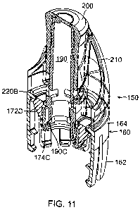
[0043] In another embodiment shown in FIGS. 11-16, a cap system 150 has the
same overall function as the
cap system 50 and other cap systems of the prior embodiments. One important
difference is that a shuttle valve
of this embodiment, valve 190, will lock into position when moved (pressed)
into its lowermost or low position,
thereby remaining fully open to the supplement storage compartment in spite of
shaking during mixing of liquid
and supplement, and in spite of movement of nipple 200, and other usage and
jostling. This promotes and/or
ensures a good mix of water and supplement and using all supplement.
7
CA 02798768 2012-11-06
WO 2011/149501 PCT/US2011/000456
[0044] Nipple 200 is the same or similar to nipple 100 and other nipples in
the previous embodiments. It is
sized to fit over shuttle valve 190. Around nipple 200 is a nipple seat and
storage compartment member 210.
This storage compartment member 210 is preferably of a rigid plastic, such as
other rigid plastic members
disclosed herein. The nipple at its lower end preferably has a rib that mates
with a rib of the storage
compartment member 210 to limit the upward movement of the nipple, or by other
means that are well known
in the art for sports bottle type nipples.
[0045] Storage compartment member 210 has a hollow circumferential section 220
open at its lower end for
mating with an upper portion of a cap member 160 thereby forming a storage
compartment 220A for
supplement. The storage compartment member 210 has two opposing curved
indentations 210A so that even
when the nipple 200 is in the downmost position (e.g., as shown in FIG. 15),
portions of the nipple are exposed
to easily grasp the nipple with a fmger and opposing thumb to lift the nipple
from the closed position to an open
position (uppermost position of the nipple, e.g., FIG. 13), so that a user may
drink from the bottle. The storage
member 210 has an inner bottom ring portion 210B to mate with an upper surface
of ring 166 of web portion
164 of the cap member. There may be small ribs to form a slight interference
fit and thus a better seal to keep
the supplement in the chamber.
[0046] In this embodiment, there is a cap member 160 that functions the same
or similar to the cap member 60
and other cap members of the prior embodiments. Generally, cap member 160 has
a lower portion with a
plurality of finger portions 162 projecting from a web portion 164. The fmger
portions 162 are the same or
substantially the same as in the prior embodiments, and preferably as depicted
here with two barbs or tabs that
operate the same as in the prior embodiments, forming an attach portion for
attaching the cap system and in
particular the cap member to the bottle. The web portion has a hollow upwardly
projecting ring portion 166, i.e.
projecting above the web portion away from the finger portions. The ring
portion 166 has a plurality of spaced
dispensing openings 166A formed between adjacent posts 166B, and these
openings will allow the supplement
material to pass through when the shuttle valve member openings 190A are
aligned with the these openings
166A of the storage chamber, as described more fully below with reference to
FIG. 13.
[0047] The cap member 160 further includes an outer circumferential surface
164A and a circumferential
vertical wall 164B extending upwardly from the web portion 164 and together
defining the outer
circumferential surface 164A. Surface 164A receives a bottom circumferential
edge of the storage
compartment member 210. The storage compartment member 210 has an inwardly
projecting circumferential
rib 220B that snap fits over and mates with an outwardly projecting
circumferential rib 164C from wall 164B,
the rib 164C being of slightly greater diameter than that of rib 220B, thereby
providing an attach feature of the
storage compartment member 210 to the cap member.
[0048] The cap system also includes a seal member assembly 170 that fits into
cap member 160, i.e., sized to
fit snugly within a barrel of the cap member formed by the fingers and pressed
upwardly against an underside of
the web portion 164 of the cap member. The seal member assembly is preferably
two members, a seal member
172 and a rigid member 174. The seal member 172 is resilient and preferably
fabricated of an elastomeric
material, such as, by way of example only, thermoplastic rubber (TPR) (molded
rubber), SBR, neoprene rubber,
8
CA 02798768 2012-11-06
WO 2011/149501 PCT/US2011/000456
or closed cell foam, and has a center opening configured for concentricity
with the opening through the boss.
The rigid member 174 is preferably a rigid plastic of a type disclosed herein
or other type of rigid member.
[0049] The rigid member 174 has upper tabs 174A that engage slots 172A of the
seal member 172 and an
upper interior substantially annular surface 174B that receives a
corresponding annular downwardly depending
tab 172B of the seal member 172. The seal member assembly 170 includes a
center opening through which the
bottle contents may pass, and a generally flat upper surface 74.
[0050] The outer periphery of the seal member 172 includes a downwardly
extending peripheral wall 172E
that also extends or tapers outwardly, and even more so at its lower and
outermost portion 172F to frictionally
engage the inner portion of the web member barrel, e.g., as shown in FIG. 11.
This shape allows the seal
member 172 to slide into the barrel relatively easily, but the outermost
portion 172F tends to expand if one
attempts to move it downward from the barrel. The seal member also has an
inwardly tapered lower surface
172D defining a partial conical seal surface which may be contacted by the
bottle neck lip when the cap system
is attached to the bottle neck, e.g., as shown in the embodiment of FIG. 3.
[0051 ] The web portion 164 has an opening or openings 164D through which
supplement can be inserted into
the chamber. The chamber could also be filled in advance, prior to assembly,
then snapped on to the cap
member at the web portion, in which case the openings 164D would not be needed
but could still be present.
The member 210 may be fabricated of a semi-transparent or transparent plastic
material such as, by way of
example only, styrene, and is configured for attachment to the cap member by
snap fit mentioned above,
although adhesive, welding or other connection method could be used. As noted
elsewhere herein, single use is
preferred for the cap system, although multiple use is possible. Shipment with
the chamber filled, or subsequent
filling by the user are possible.
[0052] The dispensing cap system 150 further includes the shuttle valve member
190 having a hollow
generally cylindrical wall portion 192, and a top web portion 194 at one end
thereof which extends across the
end of the wall portion and is for mating with the nipple when the nipple is
closed to flow of liquid. A bottom
of the shuttle valve has tabs or fingers 190B that have a gripping projection
190C at their ends. The gripping
portions engage a bottom inner annular portion 174C of the rigid member 174 of
the seal assembly to hold the
shuttle valve 190 securely in the open position as best shown in FIG. 13.
There are also boss surfaces or tabs
190D to act as downward motion stoppers that engage the upper portion of
annular portion 174C.
[0053] A tip 196 of reduced diameter relative to the wall portion 192 extends
above the surface of the web
portion 194. The sidewall of the tip has several ports (e.g., such as shown as
96A in earlier embodiments)
formed therein, and permit the beverage to pass through from the bottle when
the valve is in an open position.
The diameter of the wall portion 192 is sized in cooperation with the diameter
of the opening in the storage
member, so that the cylindrical wall portion tightly but slidably fits within
the opening.
[0054] The shuttle valve has a range of sliding movement within the storage
member, and the nipple has a
range of sliding movement on the shuttle valve, such that, when the nipple and
shuttle valve are in a closed
9
CA 02798768 2012-11-06
WO 2011/149501 PCT/US2011/000456
position as in FIG. 11, the ports are sealed by the nipple. In an open
position as in FIG. 12, the nipple does not
cover the ports 196A, allowing liquid to pass through from the bottle, so the
user can drink the beverage.
[0055] In the shipping or storage state of FIG. 11, valve 190 is positioned so
that the boss surfaces or tabs
190D may be positioned such that against the upper portion of annular portion
174C and act as temporary
downward motion stoppers. However, friction also would act to prevent
premature opening of the valve.
Further, packaging for the cap system in shipping and otherwise handling would
preferably be such to help
prevent premature opening of the valve. The interior volume of the storage
member 210, when filled with a
quantity of supplement material, cannot flow out through openings 166A because
the openings 190A of the
shuttle valve are not aligned. They are blocked by the solid wall portion of
the shuttle valve 190.
[0056] When the system 150 is installed on a bottle such as bottle 10, the
nipple 200 and shuttle valve 190
may be pressed down by the user, resulting in the tabs 190D passing downward
below the annular portion 174C
and engaging the lower surface of the annular portion. This communicates the
openings 190A in the shuttle
valve with the openings 166 in the web portion and allows supplement to mix
with liquid from the bottle. There
is an annular gap between the openings 190A and openings 166 so that actual
alignment of the openings 190A
with openings 166 is not necessary for the system to operate, although
alignment would be preferred. The user
shakes the bottle until a good mix is achieved. The openings 190A positively
stay in communication with the
openings 166, thus allowing complete mixing.
[0057] FIG. 13 shows the drinking position of the nipple 200, which has been
pulled upward to its topmost
position, opening communication with the ports in the shuttle valve. The
shuttle valve 190 stays down.
Although the foregoing has been a description and illustration of specific
embodiments of the subject matter,
various modifications and changes thereto can be made by persons skilled in
the art without departing from the
scope and spirit of the invention. For example, a lesser preferred connection
system would be threads instead of
fingers with barbs or fingers with threads, but in such case the cap system
would have to be sized for a
particular bottle. Such embodiments would not have the more universal
attachment capability of the fingers
with barbs. More fingers, such as ten, twelve or fourteen, are preferred as
such fingers will have a smaller
width relative to using fewer fingers, e.g., six. The finger and barb
dimensions and material, and the number of
fingers and barbs, and spacing between the fingers all affect the resiliency
of the fingers. The resiliency is such
that the downward force needed to apply the fingers to the bottle neck
sufficiently to form a good seal between
the seal member and bottle is less than the deformation point and failure
point of the bottle. At least ten, or at
least twelve or at least fourteen fingers helps to provide good flexibility
and resiliency to the fingers to help
reduce the downward force of application to the bottle, and yet achieve a
strength of attachment to the bottle
such that pulling up on the nipple in order to drink will not pull the cap
system off of the bottle. The force
required to apply the cap member to the bottle must be less than such force
that would cause the user to apply so
much resisting force to the bottle that the user would cause the bottle to be
crushed or otherwise fail.