Note: Descriptions are shown in the official language in which they were submitted.
CA 02799019 2012-11-08
Method and facility for producing a multilayered material panel to be divided
into beam-like
products and a material panel
The invention relates to a method for producing a multilayered material panel
according to the
preamble of Claim 1. Furthermore, the invention relates to a material panel
according to Claim
13 and to a facility for producing a multilayered material panel according to
Claim 17.
To produce wooden composite panels, discontinuous multi-daylight presses and
continuously
operating presses are typically used, in the latter, a scattered compressed
material mat having
glue-coated scattered particles being compressed under pressure and
introduction of heat
between two revolving steel belts. In addition to solely particulate panels
(MDF), machined
wood scraps are also used, which are typically scattered in an oriented
manner, to provide the
produced wooden composite panels with reinforced strength in length and width.
Types of
production are differentiated for oriented scattered panels in the
longitudinal and transverse
directions (OSB) and an orientation solely in the longitudinal direction
(OSL). Such OSB and
OSL panels are typically produced on continuous double-belt presses.
A continuous method for producing wooden composite panels is known from DE 10
2005 035
214 Al, in which a compressed material mat is formed in a scattering station
on a continuously
moving forming belt, which mat consists of one or more layers of oblong wood
scraps scattered
oriented longitudinally to the production direction or scattered oriented
longitudinally and
transversely, and which, after introduction between the steel belts, which
revolve around upper
and lower frame parts, of a continuously operating press, is cured under the
application of
pressure and heat to form an endless wooden composite panel. The method has
fundamentally
proven itself.
In the meantime, the demand of the container industry for inexpensive but
sufficiently strong and
stable floor plates for shipping, storage, office, or living containers has
proven to be of wide-
ranging economic significance. A specification of the industry for container
panels prescribes a
bending strength of 69 N/mm2 at a support spacing of 250 mm for 28 mm thick
container floors.
Other specifications prescribe higher support spacings in the comparison for
testing the bending
1
CA 02799019 2012-11-08
strength, which also result in higher bending strains. The smaller support
spacing of 250 mm
results in very high shear stresses in the neutral fibers of the panel during
the bending test,
however. Therefore, up to this point predominantly plywood panels having
densities around 900
kg/m3 have been used as the panels for container floors. In addition to the
high bending strength,
the panel surface must have a sufficient hardness and adequate abrasion
resistance. In addition,
the load which is applied by means of a wheel, for example, of a forklift, to
the panel must be
sufficiently distributed in the panel longitudinally and transversely to the
wheel via the supports
of the sheet-metal grooves on the container floor.
The main problem is that the transverse scattering is problematic in relation
to the longitudinal
scattering in the production of oriented scattered layers. Continuous
transverse scattering suffers
from many flaws and additionally requires massive trimming after the
scattering, because the
edge regions of the scattered mat made of chips or scraps are typically coated
significantly less.
However, even after massive trimming, the produced multilayer panels have
problems in the
transversely scattered layers of the panel.
Because of these high requirements, up to this point it has not been possible
to produce a panel
from scraps which meets the high requirements of industrial container
construction. On the other
hand, a replacement for plywood panels is urgently sought after, since the
required veneers for a
plywood panel are costly and, in addition, impregnation of the veneers with
fungicides (agents
which prevent fungal growth) is difficult. Since a high percentage of
containers is shipped
worldwide on container ships, many of these container panels are subject to a
high ambient
humidity in poorly ventilated spaces, which also requires a regular
replacement of the container
panels. A container plate which was already resistant or could offer a higher
level of resistance
against mold and fungus infestation in the course of production would be very
advantageous
here.
The invention is based on the object of providing a method and a facility,
using which it is
possible to produce multilayered material panels for producing multilayered
beam-like products
simply and cost-effectively. Furthermore, an oriented scattered material panel
is to be provided,
which can be used as a more cost-effective alternative or as a competing
product in relation to
2
CA 02799019 2012-11-08
the plywood panels with comparable properties. In particular, the beam-like
products are to be
used as artificially produced laminated timbers or can be used thereafter for
the use as still taller
artificially produced laminated timbers.
The object of the method is achieved in that a single-layer oriented scattered
layer mat is formed
from glue-coated scattered material, which can be oriented longitudinally in
the production
direction, in a forming station, the layer mat is compressed in a continuously
operating press to
form a single-layer oriented layer panel strand, the layer panel strand is
divided at least once by
means of a dividing device to form single-layer oriented layer panels, a layer
packet consisting of
at least three layers or a layer packet strand consisting of at least three
layers is formed in a
laying device, layer panels being used in at least two layers, and the layer
packet or the layer
packet strand is compressed in a cyclically or continuously operating press to
form a material
panel or a material panel strand, which can be divided to form a material
panel, and the material
panel is divided into beam-like products, in particular artificially produced
laminated timbers, of
greater height than width.
The achievement of the object for a material panel is that the material panel
comprises at least
three layers which are glued together, at least two layers consisting of a
single-layer oriented
layer panel.
The object for a facility is achieved in that the facility comprises at least
one laying device for
producing a layer packet or a layer packet strand from at least three layers,
layer panels being
used in at least two layers, and a cyclically operating press for compressing
the layer packet or
the layer packet strand to form a material panel or a continuously operating
press for
compressing the layer packet or the layer packet strand to form a material
panel strand and a
dividing device for dividing the material panel strand into material panels.
The facility can advantageously also have a forming station for producing a
single-layer oriented
scattered layer mat from a scattered material which can be oriented, a
continuously operating
press for compressing the layer mat to form a single-layer oriented layer
panel strand, and a
3
CA 02799019 2012-11-08
following dividing device for dividing the layer panel strand into a single-
layer oriented layer
panel.
In addition, a storage and/or transfer device can also be arranged between the
individual facility
parts, in particular between the dividing device and the laying device.
The single-layer oriented scattered production of an oriented scattered chip
panel (OSB) in a
single-layer or multilayer embodiment has already been prior art for some
time. The invention
advantageously makes use of the circumstance that the longitudinal scattering
(orienting of the
scraps in the longitudinal direction, i.e., parallel to the production
direction) can be carried out
almost perfectly in the meantime. Thus, single-layer longitudinally oriented
layer panels are
produced, which have a nearly optimum scattering value (deviation of the angle
in the
longitudinal direction of the scattered material, which can be oriented, from
the specification)
through the longitudinal scattering. These layer panels are divided
accordingly after the
compression, in particular in the case of the continuous production, a
longitudinal and/or
transverse division can be performed after the continuously operating press,
laid together to form
a layer packet, and finally glued together to form a multilayer material
panel.
Layer panels of a panel thickness of 6 mm are particularly preferably
produced, which are
subsequently glued together and compressed in five layers to form a material
panel having
approximately 30 mm thickness. With corresponding grinding down of the
surfaces before the
gluing, a material panel thickness of the final product of 28 mm results in
the typical process,
which is ideal for container flooring (laying the floor of a container).
In a partial aspect of the invention, a use of the material panel as a load-
bearing covering, in
particular as a floor covering on support surfaces, which extend in parallel
and are spaced apart,
while utilizing its special properties or preferred direction, is to be
provided. For this purpose, the
material panel, consisting of at least five layers, is arranged having the
predominant number of
layer panels oriented in the same direction transversely to a possible support
structure or support
surfaces, to bridge structure-related gaps, for example, as are present in
containers on the floor
due to the sheet-metal trapezoidal or U-profile frame structure.
4
CA 02799019 2012-11-08
The invention understands an adhesive or binder for the glue coating of the
planar sides or the
scattered material as a so-called adhesive solder, which consists in its main
components of an
adhesive. As needed, additional emulsion, curing agent, formaldehyde
scavenger, colorants,
insect protection agents and fungus protection agents and other additives are
added. It is also
typical to use the adhesive without additives. MDI (diphenylmethane
diisocyanate) or PMDI
(polymer diphenylmethane diisocyanate) from the group of isocyanates is
preferably used as the
adhesive. The proposed material panel (five-layer panel) or the use thereof
can result, on the one
hand, through the method according to the invention; however, it can also be
considered to be an
independent material panel.
Furthermore, the invention understands a layer mat as a compressed material
mat, which is
compressed in a press to form a layer panel, in the present case in particular
the layer mats
having an oriented scattering of the scattered material in the production
direction (longitudinal
direction) being meant. A layer panel which uses the material panel at least
partially, preferably
for all layers, thus consists of an oriented scattered layer panel. A single-
layer scattered layer
panel is understood in the invention as an oriented scattered layer mat in the
longitudinal
direction of the production direction, i.e., parallel to the production
direction, which when
compressed results in a single-layer layer panel, which consists of chips or
scraps oriented in one
direction. These layer panels may finally be laid together to form a layer
packet, at least one
touching side between the layers being glue coated except for the outer or
cover surfaces. The
surfaces of the layer panels to be glue coated are preferably ground down, on
the one hand, to
decrease the adhesive consumption, on the other hand, to avoid irregularities,
which could result
in separation of the individual layers during use. Of course, instead of a
layer packet, a layer
packet strand can also be formed, the butt joints between the layer panels of
one layer lying one
on top of another not being located at the same point as those of the adjacent
layers here.
Alternatively, the introduction of complete layer packets abutted or spaced
apart from one
another in a continuously operating press would also be conceivable. In this
case, the resulting
material panel strand must be divided once again, before the material panels
may result. In the
case of the formation of the layer packet or the layer packet strand from at
least two single-layer
oriented layer panels, at least one layer panel is to be laid in a different
orientation than a further
single-layer oriented layer panel. Of course, it can also be advisable if it
does not form the
middle layer in the case of an odd number of layers, for example, so that they
have the same
CA 02799019 2012-11-08
orientation in the material panel. Therefore, each layer panel can be laid on
the next layer panel
having a preferably perpendicular difference of the orientation to one another
in the laying
device. In particular, it is advantageous if a layer panel strand is divided
transversely to the
production direction to form square layer panels, since they may be stacked
best without much
clipping or cutting to size.
The layer panel strand can accordingly be divided longitudinally and
subsequently transversely
to the production direction to form square layer panels. Layer panels still
having residual heat
from the compression in the press can be laid together to form a layer packet
or a layer packet
strand. During the method, the layer panels and/or the layer panel strand are
to be treated on at
least one planar side. The glue coating of the planar sides of the layer
panels is performed before
the preparation of the layer packet or in the laying device on the layer
packet which is not yet
finished. During the preparation of a layer packet or a layer packet strand,
the butt joints between
two layer panels of a layer are to diverge from the butt joints of adjacent
layers. At least in the
case of two single-layer oriented layer panels, when the layer panels are laid
on one another, a
different orientation to one another is to be used. The scattered material is
preferably a material
containing lignocellulose or preferably has a thickness of 0.6 to 1.1 mm
and/or a width of 5 to 90
mm. The length can be from 40 to 300 mm. A plastic, a metal, a film, and/or
cork can be used to
form at least one alternative layer of the layer packet or the layer packet
strand. The layer panel
can or the layer panels are also ground on one or both sides before the glue
coating, so that the
thickness is implemented uniformly over the length and width. No flaws are
present in the glue
joint due to the grinding.
A layer packet consisting of five, seven, or nine layers or a layer packet
strand consisting of five,
seven, or nine layers is particularly preferably formed. In particular, a
layer packet consisting of
five, seven, or nine layers or a layer packet strand consisting of five,
seven, or nine layers is to be
formed in particular, each layer consisting in this case of oriented layer
panels. The layer located
in the middle preferably has a different thickness than the external layers.
The layers to be laid at
the same distance to the middle layer are also to have equal thicknesses, in
order to ensure a
uniform construction with an odd number of layers. A material panel
accordingly comprises at
least three layers which are glued together, at least two layers consisting of
a single-layer
6
CA 02799019 2012-11-08
oriented layer panel. The layer panels of different layers are to diverge in
their orientation, in
particular at a 90 angle to one another.
In a specially designed and implemented method and facility application, a
layer panel strand
produced in a continuously operating press is divided once longitudinally and
then transversely
or, vice versa, first transversely and then longitudinally. Therefore, two
adjacent layer panel rows
result on a production line, which can simply be laid one on top of the other
in a laying device, in
a corresponding sequence, the layer panels being rotated by 90 to produce the
layer packet or a
layer packet strand, which is in turn compressed. Upon a longitudinal cut and
the following
transverse division, the possibility advantageously results of also arranging
a cyclic press after a
continuously operating press, since multiple layer panels, preferably 5 or 7,
are laid one on top of
another by the laying device and a compression of a layer packet can be
carried out during the
laying procedure to form a layer packet.
The relevant laying devices are sufficiently known from veneer laying
technology. A preferably
producible material panel according to the invention thus has at least three,
particularly
preferably five or seven layers made of individual panels, the individual
panels consisting of
single-layer oriented layer panels.
In addition to the production of such material panels, the production of very
thick (beam-like)
material panels, in particular artificially produced laminated timber, would
also be conceivable.
Laminated timber (BSH) is also known as glued laminated timber or colloquially
referred to as
glued wood. Wooden boards are dried, planed, and connected to form lamellae,
mostly by means
of finger joints, and glued together (cold) in multiple layers. In particular
in large halls or
elongated bridges, glued wood can compete with other materials, in particular
steel construction,
and is distinguished by a more attractive appearance, lower weight, and
significantly longer
lifetime in case of fire. It is now proposed that (beam-like) material panels
also be manufactured
by means of the present method and facility, which can compete with these
products (glued
woods). For example, single-layer oriented layer panels which are 30 mm or
even up to 65 mm
thick could be produced from the initially produced layer panels, for example.
On the upper end,
with respect to the thicknesses, technological limits currently only exist
with respect to the
through heating of the layer mat, since with very tall layer mats and their
compression, the
7
CA 02799019 2012-11-08
continuously operating press becomes longer and longer as a result of the
compression factor.
For example, if 30 mm layer panels are laid together to form a five-layered
layer panel strand or
a layer packet, material panels can be produced therefrom, which are 150 mm
thick. If these are
divided (relatively narrow) as material panels which are 2.5 in wide and 20 in
long after a
compression which is preferably carried out cyclically, a rather beam-like
product results from
the produced material panel.
To produce such a material panel, under certain circumstances, certain
precautions would be
taken and especially cold-curing glue would be used as the binder or even
solely compression
would be carried out. It would even be conceivable to heat up the glue by
means of high-
frequency radiation, in particular microwaves. A cyclically or continuously
operating press used
in the second step (according to 1.5) would not necessarily have to be a hot
press.
The transition from material panels is thus rather flowing, one could
designate panel thicknesses
from 100 mm already as "beams", of course, but which are first cut out of the
planar panels in the
course of the division in the present application in the case of a planar
compression.
In particular with such highly complex material panel applications, it is
necessary to prepare the
surfaces before the glue coating accordingly. Very level surfaces are required
in this case, which
are typically made possible by a grinding procedure, so that optimum glue
coating or glue
bonding can be produced, respectively.
With respect to the chips, the invention understands these as chips, scraps,
flakes, or the like
which can be oriented, and which are suitable for the purpose during the
scattering of being
scattered in an oriented manner to form a layer mat. A single-layer oriented
scattered layer mat is
understood as a layer mat made of material which can be oriented, which has
predominantly
been scattered oriented and compressed, and therefore, in particular in a
sectional view, has an
unambiguous orientation of a predominant fraction of the scattered material.
For high-strength
applications, in particular to produce artificial glued wood made of
artificially produced
individual layer panels, which have been glued together and compressed in
multiple layers,
eucalyptus and/or hardwoods can achieve particularly good results. The beam-
like products are
8
CA 02799019 2012-11-08
then laid one on top of another thereafter and glued together to produce
taller artificially
produced laminated timbers.
Further advantageous measures and embodiments of the subject matter of the
invention are
provided in the subclaims and the following description with the drawing.
In the figures:
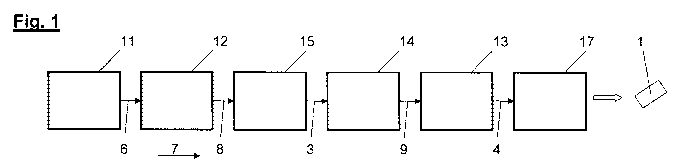
Figure 1 shows the schematically illustrated production sequence of a
production of a
material panel from a layer packet, which is prepared from multiple layer
panels,
with subsequent compression,
Figure 2 shows a three-dimensional sectional view of a material panel made of
five layer
panels, which are laid on one another and glued together,
Figure 3 shows a variant of the production sequence of a production of a
material panel
from a layer packet strand, which is prepared from multiple layer panels, and
which is compressed in a continuously operating press and subsequently divided
to form a material panel,
Figure 4 shows a schematic view of a material panel as a covering on a support
structure
with exemplary load by a pallet base and a wheel of a forklift or a pallet
lift truck,
respectively.
Figure 1 shows a schematic and exemplary production sequence for the
production of a material
panel from wood or wood-like raw materials. In a preparation 11, scattered
material 6 is prepared
and glue coated from the raw materials. The glue-coated scattered material 6
is subsequently
scattered in a forming station 12, in the parallel direction to the production
direction 7 and on a
continuous endless revolving forming belt (not shown) to form a single-layer
layer mat 8
oriented in the production direction 7. The layer mat 8 can be subjected to a
pretreatment (not
shown) before the compression, which comprises a change of the temperature,
the moisture,
and/or the density of the layer mat. Subsequently, the layer mat 8 is
compressed using a
continuously operating press 15 to form a layer panel strand 3 and
subsequently divided using a
dividing device 14 to form layer panels 9. Directly (still having the residual
heat from the
compression) or indirectly (after unloading, production location change, or
the like) after the
9
CA 02799019 2012-11-08
compression, a layer packet 4 is formed in a laying device 13. Before or in
the laying device, the
planar sides 10, which later lie adjacent to a further layer panel 9, can be
glue coated. The
compression of the layer packet 4 is performed in a press 17, which can be
implemented as
cyclically or preferably continuously operating. It would also be conceivable
in the case of a low
workload of the facility to carry out the compression to form a material panel
in the first press
15. It is also conceivable to introduce the formed layer packets continuously
having no or little
spacing into a continuously operating press and to carry out the second
compression
continuously.
This is illustrated in a variant of the production sequence according to
Figure 3. The method is
executed identically as in Figure I until, instead of a layer packet 4 made of
multiple layer panels
9 in the laying device 13, a layer packet strand 16 is prepared and this
strand is compressed in a
continuously operating press 17 to form a material panel strand 19 and
subsequently divided to
form a material panel 1 by means of a further dividing device 20.
Figure 2 shows a five-layered material panel 1 having five layers 22 of
different orientation 2 of
the layer panels 9. The orientation 2 of a layer panel 9 preferably has a
rotation of 90 to the
adjacent layer panel in the material panel 1.
According to Figure 4, in particular the use of the material panel 1 produced
according to the
method as the load-bearing covering 27 on a support structure 24 consisting of
multiple support
surfaces 25 separated by spacings 26 is preferred, the covering 27, consisting
of one or more
material panels 1, being arranged on the support structure 24 such that the
majority of the layers
22 of the material panel 1, consisting of the oriented layer panels 9, are
arranged transversely to
the extension of the support surfaces 25. I.e., the two external and the
middle layer panels 9 of a
five-layered panel are arranged so that they are aligned parallel to the
indicated support spacing
26.
Layer panels 9 are particularly preferably laid together oriented successively
longitudinally,
transversely, longitudinally, transversely, longitudinally to the production
direction 7 to form a
layer packet 4 or a layer packet strand 16, the layer panels 9 preferably
being arranged
CA 02799019 2012-11-08
substantially at right angles to one another. To illustrate the load
situation, a wheel 23 of a
forklift or a pallet lift truck is arranged on the covering 27 in Figure 4. A
pallet base 23 is located
adjacent thereto as a detail. In both load situations, a force arrow F is
shown in simplified form
perpendicular to the planar side of the covering 27.
The facility is suitable overall for carrying out the method, but can also be
operated
independently. The material panel can in particular be produced according to
the known method
and/or on such a facility. (1412)
In summary, it is to be noted that if beam-like final products are to be
produced, they do not yet
have to be implemented as beam-like (taller than wide) in step 1.6, if they
are to be used once
again for the layered construction. The invention also understands beam-like
as material
panels/beam-like products which consist in height of multiple layers 22.
11
CA 02799019 2012-11-08
List of reference numerals:
1 material panel
2 orientation
3 layer panel strand
4 layer packet
6 scattered material
7 production direction
8 layer mat
9 layer panel
planar side
11 preparation
12 forming station
13 laying device
14 dividing device
continuously operating press
16 layer packet strand
17 press (cyclic/continuous)
18
19 material panel strand
dividing device
21 wheel of forklift/pallet lift truck
22 layer
23 pallet base
24 support structure
support surface
26 spacing
27 covering
12