Note: Descriptions are shown in the official language in which they were submitted.
CA 02799255 2012-12-19
WATER REMOVING HAIR BRUSH
Background
1. Field of the Disclosure
[0001] The present invention is generally directed to hairstyling implements,
and more
particularly to water removing hairstyling implements, such as brushes.
2. Description of Related Art
[0002] In order to save time during hairstyling, it is desirable to reduce the
amount of
time it takes to dry hair, because wet hair generally cannot be styled. Towels
are the
most common way to absorb water from wet hair. Towels are sometimes configured
as
head wraps to increase the amount of contact with the hair. Nevertheless,
towels
typically fail to sufficiently dry hair for styling. Moreover, efforts to
increase drying
effects by rubbing or moving the hair with the towel can result in undesirable
styling
effects at a minimum, and worse, can damage the hair.
[0003] Others have tried to create products that can remove more water than a
conventional towel. Combs that are otherwise traditional have been made with
teeth that
can move and act as a squeegee on wet hair. Other combs have added chemical
additives
to dissipate moisture or to break up the water molecules. Such combs have not
been
found to markedly remove or dissipate moisture in wet hair or to significantly
reduce
drying and/or styling time.
[0004] Hair brushes have been created that perform a task opposite to that of
absorbing
water from hair. Such hair brushes and other implements have been developed
that apply
or distribute oil, hair coloring agents, or conditioners to the hair and
scalp. Other hair
brushes have been created to absorb water, but these lack vents or a means of
promoting
1
CA 02799255 2015-06-03
air flow so are difficult to dry and have limited absorbing capacity. Examples
of such
products are disclosed in, for example, U.S. Patent No. 7,461,659.
[0005] Other products have an absorbent capability for absorbing styling or
coloring
agents for applying such agents to hair. Examples of such products are
disclosed in, for
example, U.S. Patent No. 5,002,075, U.S. Patent No. 5,261,426, U. S. Patent
No.
5,301,695, U.S. Application Serial No. 2008/014504, EP 1272068, and EP
0497080.
Summary
PM] In one example according to the teachings of the present invention, a
hair brush
has a body with a head and has a plurality of bristles carried by and
protruding relative to
the head. A water absorbent material is carried by part of the body. The body
has one or
more vents.
[0007] In one example, the body can have a handle coupled to the head. In one
example, the water absorbent material can be carried by the head.
[0008] In one example, the head can be generally rectangular in shape and can
also
define a cavity within the head. The one or more vents can be in communication
with the
cavity.
[0009] In one example, the head can be generally oval in shape and can also
define a
cavity within the head. The one or more vents can be in communication with the
cavity
[0010] In one example, the plurality of bristles can be connected to a bristle
pad that is
carried by the head.
[0011] In one example, a bristle pad can carry the bristles and can have a
plurality of
perforations formed therethrough. The plurality of bristles can be
interspersed among the
perforations. In one example, the perforations can be formed through a surface
of the
head, can be separate from the one or more vents, and/or can be one and the
same as the one
or more vents.
[0012] In one example, the water absorbent material can overlie a bristle pad
or a
surface of the head and the plurality of bristles can protrude through the
water absorbent
material and from the head.
2
CA 02799255 2012-12-19
[0013] In one example, the water absorbent material can have exposed edges
wrapped
over perimeter edges of a bristle pad and can be captured between the head and
the bristle
pad.
[0014] In one example, the head can be paddle shaped.
[0015] In one example, the head can have a front housing section joined to a
back
housing section and can have a retention plate disposed therebetween. The
front housing
section can have an aperture with a bristle pad and/or the water absorbent
material seated
therein.
[0016] In one example, a retention plate in the head can have a top section
with a
serrated ridge on a top surface and a support leg joined perpendicular to the
top section.
The water absorbent material can be anchored against the serrated ridge inside
the head.
[0017] In one example, the head can have a front housing section, a back
housing
section, or both that include a plurality of vent holes forming the one or
more vents.
[0018] In one example, the water absorbent material can be a microfiber
fabric.
[0019] In one example, the water absorbent material can have a plurality of
flexible
rods extending from a base substrate. In one example, the base substrate and
the flexible
rods can be of a microfiber fabric.
[0020] In one example, the plurality of bristles can protrude through the
water
absorbent material. In one example, the bristles can protrude through a
microfiber fabric
and can be interspersed among a plurality of flexible fabric rods of the
microfiber
material.
[0021] In one example, the water absorbent material can be a microfiber fabric
including a base substrate and fabric rods protruding therefrom generally
parallel to the
bristles. In one example, such fabric rods can be arranged in rows and columns
of a
spacing that matches a spacing of the plurality of bristles.
[0022] In one example, the water absorbent material can have antibacterial
properties.
3
CA 02799255 2012-12-19
[0023] In one example, the water absorbent material can be positioned on one
side of
the head and the plurality of bristles can protrude from the same side of the
head in a ring
around a perimeter of the water absorbent material.
[0024] In one example, the water absorbent material can be a microfiber fabric
with an
exposed surface texture.
[0025] In one example, an exposed surface texture of the water absorbent
material can
be a heat stamped pattern on a microfiber fabric or other material.
[0026] In one example, an exposed surface texture of the water absorbent
material can
be a sewn quilted pattern on a microfiber fabric or other material.
[0027] In one example, an exposed surface texture of the water absorbent
material can
be formed of relatively narrow strips of a microfiber fabric or other material
woven
together.
[0028] In one example, the water absorbent material can be on one side of the
head and
the plurality of bristles can be on the same side of the head. The plurality
of bristles and
the water absorbent material can be arranged in alternating concentric rings.
[0029] In one example, the water absorbent material can be a microfiber fabric
that
overlies a bristle pad carrying the plurality of bristles. The microfiber
fabric can have a
thickness that is less than a length of the bristles. The bristles can
protrude through the
fabric.
[0030] In one example, the brush can have rows or columns of the plurality of
bristles
protruding from a bristle surface on the head. Elongate slots can be arranged
between the
rows or columns of bristles. A plurality of rods can protrude from the water
absorbent
material. The water absorbent material can underlie the bristle surface and
the rods can
protrude through the elongate slots forming alternating rows or columns of
bristles and
rods.
[0031] In one example, the head can be a cylinder and the body can have a
handle
extending from an end of the cylinder. A plurality of bristles can protrude
radially
outward from a surface of the cylinder.
4
CA 02799255 2012-12-19
[0032] In one example, the water absorbent material can be arranged on a
surface of a
cylindrical head.
[0033] In one example, the water absorbent material can spiral around an outer
surface
of a cylindrical head. The water absorbent material and the plurality of
bristles can be
arranged to form alternating spirals along a length of the cylinder.
[0034] In one example according to the teachings of the present invention, a
hair brush
has a body with a head and has a water absorbent material carried by the body.
The
water absorbent material can be a foam material.
[0035] In one example, the body can have a handle coupled to the head and the
foam
material can be carried on the head.
[0036] In one example, the head can be paddle shaped and the foam material can
include a plurality of vanes protruding from a surface of the head.
[0037] In one example, a plurality of foam material vanes can be provided
having
different lengths and can protrude from a surface of the head.
[0038] In one example, the head can have one or more rows or columns of teeth
or
bristles arranged at or near perimeter edges of the head. The foam material
can be at least
partially surrounded by the rows or columns of teeth and can protrude from the
same side
of the head as the rows or columns of teeth.
[0039] In one example, the head can be paddle shaped and the foam material can
be in
the form of serpentine waves or loops arranged in aligned rows or columns on a
side of
the head.
[0040] In one example, the foam material can be arranged having two or more
spaced
apart ridges protruding from a surface of the head. A plurality of bristles
can be arranged
alternating with the two or more spaced apart ridges and protruding from the
surface of
the head.
[0041] In one example, the foam material can be arranged in multiple ridges
protruding from a surface of the head. A plurality of bristles can be arranged
in
alternating rows or columns on and protruding from the surface of the head.
CA 02799255 2012-12-19
[0042] In one example, the head can be a cylinder and can have a handle
extending
from an end of the cylinder. The foam material can protrude from an outer
surface of the
cylinder.
[0043] In one example, the hair brush can have a plurality of bristle cores
protruding
from the head and each can be covered by or coated with the foam material.
[0044] In one example, the head can have a back side and a recess formed in
the back
side and can have has a front side. A plurality of perforations can be formed
through the
head within the recess. The foam material can have a block seated in the
recess and can
have a plurality if bristles protruding from the block and extending through
corresponding ones of the plurality of perforations to protrude from the front
side of the
head.
[0045] In one example, the body of the hair brush can have a support plate
with a
bristle face on one side, a bridge spaced from the support plate on the side
opposite the
bristle face, a core of the foam material captured between the bridge and the
support
plate, and a plurality of bristles protruding from the bristle face. The
plurality of bristles
each can have a center core of a non-absorbent material covered by or coated
with the
foam material.
[0046] In one example, the body of the hair brush can have a support plate
with a
bristle face on one side, a bridge spaced from the support plate on the side
opposite the
bristle face. The bridge can have an arc shape and connect to opposed ends of
the
support plate. A core of the foam material can be captured between the bridge
and the
support plate.
Brief Description of the Drawings
[0047] Objects, features, and advantages of the present invention will become
apparent
upon reading the following description in conjunction with the drawing
figures, in which:
[0048] Fig. 1 shows a perspective view of one example of a hair brush
according to the
teachings of the present invention.
[0049] Fig. 2 shows a lengthwise cross section taken along line X-X of the
hair brush
of Fig. 1.
6
CA 02799255 2012-12-19
[0050] Fig. 3 shows an exploded view of the hair brush of Fig. 1.
[0051] Fig. 4 shows a front view of the hair brush of Fig. 1.
[0052] Fig. 5 shows a back view of the hair brush of Fig. 1.
[0053] Fig. 6 shows a portion of a manufactured blank of absorbent material
for the
hair brush of Fig. 1.
[0054] Fig. 7 shows a perspective view of a segment of the absorbent material
of Fig.
1.
[0055] Fig. 8 shows a perspective view of another example of a hair brush
according to
the teachings of the present invention.
[0056] Fig. 9 shows a perspective view of another example of a hair brush
according to
the teachings of the present invention.
[0057] Fig. 10 shows a perspective view of another example of a hair brush
according
to the teachings of the present invention.
[0058] Fig. 11 shows a perspective view of another example of a hair brush
according
to the teachings of the present invention.
[0059] Fig. 12 shows a perspective view of another example of a hair brush
according
to the teachings of the present invention.
[0060] Fig. 13 shows a perspective view of another example of a hair brush
according
to the teachings of the present invention.
[0061] Fig. 14 shows a perspective view of another example of a hair brush
according
to the teachings of the present invention.
[0062] Fig. 15 shows a perspective view of another example of a hair brush
according
to the teachings of the present invention.
[0063] Fig. 16 shows a perspective view of another example of a hair brush
according
to the teachings of the present invention.
[0064] Fig. 17 shows a perspective view of another example of a hair brush
according
to the teachings of the present invention.
7
CA 02799255 2012-12-19
[0065] Fig. 18 shows an opposite side perspective view of the hair brush of
Fig. 17 in
an unassembled condition.
[0066] Fig. 19 shows a perspective view of another example of a hair brush
according
to the teachings of the present invention.
[0067] Fig. 20 shows a detail cross section taken along line XX-XX of a
bristle portion
of the hair brush of Fig. 19.
[0068] Fig. 21 shows a perspective view of another example of a hair brush
according
to the teachings of the present invention.
Detailed Description of the Disclosure
[0069] In view of the foregoing, there exists a need for a hairstyling
implement that
can aid in accelerating hair drying during styling. The hairstyling brushes
disclosed
herein are well suited for aiding in the hair drying process. The disclosed
hair brushes
solve or improve upon one or more of the above-noted and/or other problems and
disadvantages with prior known hair brushes. The disclosed styling tools
remove water
by employing absorbent materials and cause no damage to hair.
[0070] Turning now to the drawings, Figs. 1-7 show one example of a
hairstyling
implement or hair brush 10 according to the present disclosure. The hair brush
10, as
shown in Fig. 1, includes a body 12 with a handle 14 and a head 16. The hair
brush 10
also has a plurality of bristles 18 and a water absorbent material 20 to
absorb water from
wet hair. The handle 14 extends from one end 15 of the head 16. The head 16 in
this
example is paddle-shaped and is somewhat rectangular, although other head
shapes may
be used.
[0071] The hair brush 10 is for use as a hairstyling implement that also can
dry hair
simultaneously as the hair is brushed and styled. The water absorbent material
20 on the
brush head 16 absorbs and removes water from the hair during styling. The
water
absorbent material 20 is disposed proximal to the bristles 18. In this example
of Figs. 1-
7, the bristles 18 extend from one side of the head 16 and through the water
absorbent
material. A user need not alter the usual way that they style or brush their
hair with such
a brush. Drawing the brush over wet hair causes strands of hair to be
separated by the
8
CA 02799255 2012-12-19
bristles. Thus, wet strands of hair will contact the water absorbent material
20, which
will absorb and remove water from the hair, thereby reducing the amount of
time it takes
to dry and style hair.
[0072] The handle 14 in this example has a shape that transitions to a shape
of the head
16 through a neck 21. The relatively narrow width of the handle 14 widens at
the neck
21 to match the width of the head 16. As shown in the cross section of Fig. 2,
the head
16 has a depth. The depth of the head 16 can have a tapered profile, being
somewhat
thicker at the neck 21 and handle end 15 and relatively thinner at a top end
17 of the head
16. As shown in Fig. 2, the neck 21 profile has a step or is angled toward a
back side 22
of the hair brush 10.
[0073] As shown in Fig. 2, the hair brush 10 further includes a bristle pad 24
on and
connected to a front side of the head 16. The bristle pad 24 has a plurality
of perforations
26 and supports the plurality of bristles 18. The water absorbent material 20
overlies the
bristle pad 24 in this example. The water absorbent material 20 is disposed
adjacent to
the bristle pad 24 with the plurality of bristles 18 protruding fully
therethrough.
[0074] The brush body 12 may be constructed from one or more pieces. In this
example, the brush body 12 has two pieces as shown in Fig. 3, including a
front housing
section 28 and a back housing section 30. The front housing section 28
includes a handle
portion defining part of the handle 14 and a head portion defining part of the
head 16.
The front housing section 28 has an outside surface 38 and an inside surface
40 and has
an aperture 42 in the head portion to receive the bristle pad 24. The front
housing section
28 includes a mating surface 44 at an edge between the outside surface 38 and
the inside
surface 40. The mating surface 44 is located around a perimeter of the front
housing
section 28.
[0075] The back housing section 30 also includes a handle portion defining
part of the
handle 14 and a head portion defining part of the head 16. The back housing
section 30
has an outside surface 46 and inside surface 48. The back housing section 30
also
includes a mating surface 50 at an edge around a perimeter of the back housing
section 30
between the outside surface 46 and the inside surface 48. The inside surface
48 can also
include supports 51 protruding forward therefrom to support the bristle pad
24. The
9
CA 02799255 2012-12-19
supports 51 are in the form of spaced apart thin walls that project from the
inside surface
48 at an angle approximately normal to the longitudinal axis of the brush body
12. The
supports 51 do not extend completely laterally across a width of the brush
body 12. Two
such supports 51 are shown, but the number, shape, orientation, and position
of such
supports can vary. The supports 51 in this example have a notched or serrated
free edge
52 to aid in positionally retaining the water absorbent material 20 during
use.
[0076] The mating surface 44 on the front housing section 28 is adapted to
engage the
mating surface 50 of the back housing section 30 when the body 12 is
assembled. As
shown in the exploded view of Fig. 3, the front housing section 28 has
positioning
elements or guide holes 53 and the back housing 30 has corresponding
positioning
elements or guide pins 54. The guide holes 53 are adapted to receive the guide
pins 54 to
properly align the two housing sections when assembled. The guide holes 53 and
the
guide pins 54 may be located inward from the perimeter of the back housing
section 30
and front housing section 28 respectively. The relative positions and
locations of the
guide holes and guide pins on the front or back housing sections may be
reversed.
[0077] A cavity 56 under the bristle pad 24 is defined by the assembled head
portions
of the front housing section 28 and the back housing section 30. The back
housing
section 30 has a plurality of vent perforations 58 providing openings to the
cavity 56 to
provide for air flow into, through, and out of the cavity 56. In the present
example, the
vent perforations 58 are arranged on lateral side walls 59 of the back housing
section 30.
The number and arrangement of the vent perforations can vary in location and
can be
uniform, random, and/or can vary in size.
[0078] The bristle pad 24, as shown in Figs. 2 and 3, is formed of a strong
yet flexible
material such as nylon. The bristle pad 24 also defines a front side of the
cavity 56 by
covering the aperture 42 in the head portion of the front housing section 28.
The bristle
pad 24 includes a front surface 60 and a back surface 62 and is generally
planar. The
bristle pad 24 supports the plurality of bristles 18 in a geometric grid of
rows and
columns. In this example, the bristles 18 are arranged on the front surface 60
of the
bristle pad 24. The plurality of bristles 18 extend outward from and generally
perpendicular to the front surface 60 of the bristle pad 24 in a direction
opposite the back
CA 02799255 2015-06-03
surface 62. The plurality of bristles 18 may be integrally formed or molded
with the
bristle pad 24 from the same flexible material.
[00791 The perforations 26 in the bristle pad 24 are arranged in rows and
columns
among and between each of the bristles 18. In this example, the perforations
26 have a
square shape. The perforations 26 form a grid-like mesh with cross points and
each of
the bristles 18 is integrally molded on the bristle pad at the cross points of
the grid. Other
arrangements, shapes and sizes of perforations 26 can be used and remain
within the
teachings of the present invention. The perforations 26 allow additional air
to flow into,
through, and out of the cavity 56 through the bristle pad 24. Air can also
flow through
the cavity via the vent perforations 58 in the back housing section 30.
100801 The bristle pad 24 can have a plurality of interlock projections 66
arranged
around and protruding radially outward from its perimeter. The interlock
projections 66
can have a predetermined shape protruding outward from the perimeter of the
bristle pad
24. The bristle pad projections 66 can interlock with and seat in
corresponding interlock
notches 67 adjacent the aperture on the front inside surface 40 of the front
housing
section 28. The projections 66 and notches 67 align and position the bristle
pad 24
during assembly. Other alignment pins, holes, mechanisms, etc. could also be
used in
place of the projections and notches.
100811 Also shown in Figs. 2 and 3, the hair brush 10 includes a retention
plate 68 in
the cavity of the head 16 to assist in retaining the bristle pad 24 and the
absorbent
material 20 in place. The retention plate 68 has a top section 70 and a leg
72. The leg 72
extends from an underside of the top section 70 and is arranged perpendicular
to the top
section 70. The top section 70 of the retention plate 68 has a top surface 74.
A notched
or serrated ridge 77 is arranged on the top surface 74 of the top section 70.
The top
section 70 can also have a plurality of perforations 75 so as to enhance air
flow through
the cavity 56 during use of the hair brush 10. The retention plate 68 seats
within the
cavity 56 with the leg 72 oriented perpendicular to the inside surface 48 of
the back
housing 30. The top such section 70 of the retention plate 68 also has guide
pins 78 and
guide holes 79 in order to be retained securely in place within the cavity 56.
11
CA 02799255 2015-06-03
[0082] The hair brush 10 of Figs. 1-7 is only one example of a hair brush
configuration
that can be used according to the present invention. The shape of the hair
brush 10 is not
necessarily limited to a paddle style brush as shown, with a somewhat
rectangular head,
but may include other shapes of brush heads including, but not limited to,
other examples
disclosed herein.
[0083] The water absorbent material 20 in one example can be a microfiber
fabric 80.
As shown in Figs. 6 and 7, the microfiber fabric 80 have a continuous base
substrate 82
and rows and columns of flexible fabric rods 36 formed extending from the base
substrate. The microfiber fabric 80 can be manufactured in a sheet or blank of
multiple
uncut microfiber fabric segments. The flexible fabric rods 36 can be a
chenille, i.e.
relatively short lengths of soft, tufted cord, in one example, and can be
woven of the
microfiber material. The rows and columns of fabric rods 36 are manufactured
on the
base substrate 82. The columns of fabric rods 36 can have the same width as a
width of
the arrangement of the plurality of bristles 18 on the bristle pad 24. The
columns of
fabric rods 36 can be spaced apart on the continuous blank or sheet by base
substrate
sections having no fabric rods thereon. This can ease the process of cutting
the
microfiber fabric sheet into appropriately sized segments 84, as shown in Fig.
7, and to
allow for assembly as described below. The sheet or blank can have a width
designed to
precisely fit a length or width of the bristle pad 24. The spacing of the
segments of the
fabric rods can be designed to fit the length or width. The blanks or sheets
of the fabric
can then be cut along cut lines C-C crosswise, for example, to fit the width
of the bristle
pad 24 with essentially no waste. Assembly of the brush 10 may then
necessitate that
only the base substrate 82 is wrapped around sides of the bristle pad 24 and
any fabric
rods remain free along sides of the head 16.
[0084] The microfiber fabric 80 can alternatively be manufactured in blank
form
having a continuous substrate and in which rows and columns of the flexible
fabric rods
are intermittently omitted at intervals corresponding to a length and width of
a bristle
pad. When the microfiber fabric is thus manufactured in sheets of multiple
uncut
segments, once cut the base substrate material can be wrapped around both of
the sides
and the ends of the bristle pad 24.
12
CA 02799255 2012-12-19
[0085] The microfiber fabric 80 can have antibacterial properties. An
antimicrobial
additive, e.g. triclosan or a suitable alternative can be applied to the
microfiber fabric or
other water absorbent material that may be used in the making of the disclosed
hair
brushes.
[0086] During assembly, blank segments 84 of the microfiber fabric 80 are
first cut to
the appropriate size from the larger sheets. Each cut blank segment 84 of the
microfiber
fabric 80 is then placed over a bristle pad 24. The plurality of bristles 18
can then
penetrate and protrude through the base substrate 82 can be the microfiber
fabric. As a
result, the fabric rods 36 on the substrate 82 are arranged among and between
the bristles
18. Edges
86, either cut sides or selvedges, of the microfiber fabric base substrate 82
are
wrapped around and overlap edges of the bristle pad 24. Together the bristle
pad 24 and
the microfiber fabric 80 are inserted into the aperture 42 in the front
housing 28. The
retention plate 34 is placed between the back surface 62 of the bristle pad 24
and the
inside surface 48 of the back housing section 30. The edges 86 of the
microfiber fabric
blank segment 84 that is wrapped around the bristle pad 24 will be borne
against the
retention plate 34 and the serrated edge 52 of the supports 51 will anchor the
fabric inside
the cavity 56 of the head 16 of the hair brush 10.
[0087] During assembly of the brush body 12, the guide pins 54 allow the front
housing section 28, and the back housing section 30 to be fitted together
precisely with
the microfiber fabric blank segment 84 and bristle pad 24 in place and
captured
therebetween. When the mating surfaces 44, 50 of the front and back housing
sections
28, 30 are connected, the cavity 56 is formed between the inside surface 48 of
the back
housing section 30 and the inside surface 40 of the front housing section 28.
The cavity
56 can extend into the handle 14 of the brush body 12, as in the example of
Figs. 1-7.
[0088] The brush body 12 can be formed in other different ways and have a
variety of
different constructions with additional and or alternate features. In the
present example,
the front housing section 28 and back housing section 30 can be joined by
sonic welding.
Alternatively, the front housing section and back housing section may have
complementary features that snap together. In another alternative, the front
housing
section and the back housing section may be joined with an adhesive or with
removable
13
CA 02799255 2012-12-19
fasteners. In another alternative, the hair brush body may be constructed from
a single
unitary piece.
[0089] The hair brush 10 can be used in styling hair in the same manner as a
typical
hair brush. The water absorbent material can draw water out of wet hair and
more
quickly dry the hair than a typical hair brush alone. Merely brushing wet hair
with the
hair brush 10 can reduce drying and styling time because the water absorbent
material
draws water from the hair more quickly than evaporation alone.
[0090] Another advantage of the hair brush 10 over a typical hair brush is
that, in
addition to aiding in creating a hairstyle, it also can reduce the time to dry
hair during
styling when used with a blow dryer for hair. When used in conjunction with a
typical
blow dryer, water is drawn out of the hair by the absorbent material and warm
air is
forced over and through the hair. The warm air can then pass through the
perforated
bristle pad, into the cavity and out the vents in the body, or vice versa.
Such air flow can
continuously evaporate water from the water absorbent material simultaneous
with the
evaporating water from the hair. This allows the water absorbent material to
continue to
draw water from the hair, further reducing drying time. The variety of
disclosed brushes
can allow a user to complete virtually any hair styling steps that would
otherwise be
completed using a brush of comparable shape but with no water absorbent
material.
Thus, a user need not change brushes during styling and will require no
learning curve to
style with one of the disclosed brushes.
[0091] In another example as illustrated in Fig. 8, a hair brush 100 has a
body 102 with
a handle 104 joined to a head 106. The head 106 in this example has a somewhat
flattened rectangular paddle style shape, similar to head 16. The head 106 has
rounded
corners and has a depth or thickness. The head 106 can have an aperture in a
front of the
head 106, similar to the aperture 42. The head 106 carries a plurality of
bristles 108 and
an absorbent material 110 that seat in the aperture 107. The plurality of
bristles 108 in
this example is in a ring arranged adjacent and around a perimeter of the
water absorbent
material 110. The water absorbent material is positioned entirely within the
bristle ring,
in contrast to example above in which the bristles protrude through a
microfiber fabric.
The bristles 108 can be integrally molded with a base or bristle pad 114 or
can be
14
CA 02799255 2012-12-19
individually mounted on the base. The water absorbent material 110 can be
provided as
an absorbent block of material or as a microfiber fabric.
[0092] In the example of Fig. 8, the exposed surface 111 of the microfiber
fabric can
have a texture 112. The texture 112 can be applied, added, or created on the
microfiber
fabric 111 in a number of different ways. The texture 112 can be applied by
heat
stamping or sewing the texture onto the microfiber fabric surface 111. In
another
alternative, the texture 112 of the microfiber fabric can be applied by
weaving relatively
narrow strips of microfiber fabric together to form larger sheets of fabric
having a
relatively greater thickness. Such a weave can increase the effective
thickness of the
microfiber fabric thereby increasing its absorbent characteristics. The
purpose of adding
texture to the absorbent material or microfiber fabric is to increase the
absorbent surface
area of the contact surface 111 of the water absorbent material 110.
[0093] As shown in Fig. 8 and as stated above, the plurality of bristles 108
can be
supported on the bristle pad 114 that surrounds the water absorbent material.
The water
absorbent material can overlie a portion of the bristle pad 114. The bristle
pad or base
substrate 114 can be sized to fill the aperture in the head 106, can be formed
of a flexible
material, and can have perforations to allow air flow through a brush body
cavity during
hairstyling and for drying the water absorbent material afterward. The brush
body 102
can be constructed in essentially the same manner as the body 12 of the brush
10, if
desired.
[0094] In another example as illustrated in Fig. 9, a hair brush 200 has a
body 202 with
a handle 204 extending from a paddle shaped head 206. The head 206 in this
example
has a plurality of bristles 208 and a water absorbent material 210 exposed on
the same
surface of the head. The bristles 208 in this example are arranged in a series
of
concentric rings alternating with a series of concentric rings of the
absorbent material
210. The alternating rings are graduated in size, growing smaller toward a
central area
214 of the head 206. In this example, the smallest ring of bristles surrounds
the central
area 214 covered by the water absorbent material 210. The water absorbent
material 210
can be a microfiber fabric. Such a microfiber fabric in this and in other
examples can
have a texture, as discussed above, or can be woven in a manner similar to
terrycloth as is
CA 02799255 2012-12-19
commonly used in cotton towels. The bristles 208 can be supported on a bristle
substrate
or pad 212. The water absorbent material 210 or at least a portion thereof can
be
disposed under the bristle substrate 212 with absorbent material texture or
segments
protruding through the pad or substrate. Alternatively, the water absorbent
material rings
can each overlie the pad or substrate 212. The bristle pad or substrate 212
can have
perforations to allow air flow through the brush during drying and styling of
the hair. A
separate support component can underlie one or both of the bristle pad 212,
the water
absorbent material 210, or both, though not necessary to the teachings of this
or any other
example.
[0095] Fig. 10 shows an example of a hair brush 300 having a cylindrical head
or
round brush head. The hair brush 300 has a body 302 with a handle 304
extending from
one end of a cylindrical head 306. The handle 304 can be shaped so as to be
comfortable
to hold, as can any of the other handles disclosed and described herein. The
body has a
neck 305 that provides for a transition from the shape and diameter of the
handle 304 to
the shape and diameter of the head 306. The neck 305 can be narrower in
diameter than
either the handle 304 or the head 306. The diameter of the cylindrical head
306 can vary
based on the hairstyling effects desired. A relatively larger diameter
cylindrical head is
used to form larger hair curls and a relatively smaller diameter cylindrical
head is used to
form smaller hair curls.
[0096] In the example of Fig. 10, the head 306 is a cylinder and has a
plurality of
bristles 308, protruding through, mounted on or integrally molded to the outer
surface of
the head 306. The bristles 308 extend radially outward relative to a
lengthwise axis Y-Y
of the body 302. The head 306 has an absorbent material 310 mounted on another
part of
the head. The bristles 308 and the water absorbent material 310 can be
arranged in
alternating spirals or helical patterns over the length of the cylindrical
shape of the head
306. When viewed from one side of the head 306, the plurality of bristles 308
and the
water absorbent material 310 can appear to form spiral stripes around the head
in the
manner of a barber pole or a candy cane.
[0097] In the example of Fig. 10, the water absorbent material 310 can again
be a
microfiber fabric. The microfiber fabric can be supported and wrapped around a
portion
16
CA 02799255 2012-12-19
of the head 306 so as to underlie a substrate or base 312 supporting the
bristles 308 on the
head 306. Alternatively, the water absorbent material 310 can overlie a
substrate that
supports bristles, the outer surface of the brush or both. Portions of the
head 306 or the
base or bristle substrate 312, even between the bristles 308, can be
perforated to further
allow air flow through the head to reduce styling time and to aid in drying
the water
absorbent material 310 in between uses.
100981 Fig. 11 shows another example of a hair brush 400 with a body 402 and a
handle 404 joined by a neck 406 to a head 408. The head 408 has a plurality of
bristles
410 and a water absorbent material 412 positioned on the same surface of the
head. In
this example, the water absorbent material does not have fabric rods as
disclosed in the
example of Fig. 1, but has a surface texture 414. The bristles 410 extend
through the
water absorbent material. The water absorbent material 412 overlies a bristle
substrate,
pad, or base (not shown). The water absorbent material can again be a
microfiber fabric.
The microfiber fabric can have a loose textured surface such as that of a
terry cloth
material, typically used in cotton toweling, but woven or formed of
microfiber.
Otherwise, the structure of the example of Fig. 11 can be similar to the
example of Fig. 1.
In this example, the bristles 410 are again arranged in rows and columns,
though not as
closely spaced.
[0099] Fig. 12 shows another example of a hair brush 500 having a body 502
with a
handle 504 extending from a head 506. The head 508 in this example is a
somewhat
flattened rectangular paddle style head similar to the example of Fig. 1. The
head 508
has a plurality of bristles 510 and a water absorbent material provided by a
plurality of
absorbent rods 512 attached to a base substrate 514. The bristles 510 are
supported by
and arranged in rows and columns on a base, substrate, or bristle pad 516. The
absorbent
rods 512 and the base substrate 514 can be formed of a microfiber fabric. The
bristle
base or pad 516 can have elongate slots 518 arranged between rows or columns
of the
bristles 510. When assembled, the bristle base or pad 516 can overlie the base
substrate
514 of the water absorbent material while allowing the rods 512 to extend
through the
elongate slots 518 from a back to a front between the rows or columns of
bristles. The
elongate slots 518 also can be configured to allow air to pass through the
bristle base or
pad 516 during styling. The brush body 502 can have a cavity defined within
the brush
17
CA 02799255 2015-06-03
body. Sides or a back of the brush body 502 can include vent holes 520 or
perforations
through to the cavity to allow air to flow through the brush during drying and
styling, as
with any of the prior examples.
(001001 Figs. 13 and 14 show additional examples of water absorbing
hairstyling
implements 600, 700. The hairstyling implements 600, 700 in these examples
employ a
water absorbing material of a foam construction. In the example of Fig. 13,
the styling
implement 600 has a body 602 with a handle 604 connected by a neck 606 to a
head 608.
The head 608 has thin sheets of water absorbing foam joined to a surface 614
of the head
in serpentine waves or loops 610. The waves or loops 610 can be joined to the
head 608 in
spaced apart rows arranged on the surface 614 of the head 608. The rows can be
spaced
longitudinally along a longitudinal axis Z-Z of the body 602 and can each
extend laterally
across a width of the head 608. The waves or loops 610 can be configured to
maximize
contact with wet hair during styling. In the present example, the foam waves
or loops 610
vary in length and are longer nearer the axis Z-Z of the head 608. The length
of each loop
can be uniform or can vary relative to other of the loops or rows. The width
of each loop is
uniform with the others in this example, but can vary and remain within the
teachings of
the present invention. The hairstyling implement 600 of Fig. 13 also includes
a column of
comb-like teeth 612 on each of the two longitudinal sides of the head 608. The
water
absorbent foam material is disposed between the rows of teeth. The teeth 612
can aid in
detangling hair while directing strands of hair over the foam loops 610. The
teeth 612 can
be omitted and yet the styling implement 600 remains within the teachings of
the present
invention.
[00101] Fig. 14 shows one such example of a hairstyling implement. The styling
implement 700 of Fig. 14 has a body 702 with a handle 704 connecting at a neck
706 to a
head 708. The head 708 has thin sheets of water absorbing foam forming vanes
710
protruding from one surface 712 of the head. The vanes 710 can be joined to
the surface
712 on the head 708 in any suitable manner or can extend through slots in the
surface
712. The vanes 710 are arranged edge to edge in columns oriented parallel
relative to a
longitudinal axis W-W of the body 702. Alternatively, the vanes 710 can be
oriented in
rows laterally across and perpendicular relative to the longitudinal axis W-W
of the body
702. The vanes need not be in rows or columns, but instead could be arranged
randomly
18
CA 02799255 2012-12-19
on the surface 712. In another alternative, comb-like teeth could be added to
sides of the
head or to another position on the head to aid in guiding wet hair over the
absorbent
vanes. Bristles could also be interspersed among the waves or loops 610 in
each of these
examples.
[00102] Figs. 15 and 16 show additional examples of water absorbing hair
brushes. In
Fig. 15, a hair brush 800 has a body 802 with a handle 804 joined at a neck
806 to a head
808. The head 808 in this example is a somewhat flattened rectangular or oval
paddle
style head. The head 808 carries a plurality of bristles 810 and a water
absorbent
material. The water absorbent material is arranged in parallel ridges 812
formed of a
foam material such as a small open cell foam. The brush body 802 has a
longitudinal
axis A-A. The bristles 810 are arranged in columns parallel to the
longitudinal axis A-A.
The ridges 812 are arranged parallel to and in alternating columns with the
columns of
bristles 810. The foam ridges 812 can extend substantially the length of the
head 808.
The absorbent foam ridges 812 can be attached on top of a front surface 814 on
the head
808. Alternatively, the front surface 814 of the head 808 can include slots
816 for
receiving foam ridges 812 that pass through from a back side of the front
surface 814 to
protrude outward from the head 808. The ridges 812 can thus be connected to a
larger
foam base or block (not shown) with a cavity of the head 808. The bristles 810
can be
attached to or extend through the front surface of the head 808. The bristles
810 can be
mounted individually on the front surface 814. Alternatively, the bristles 810
can be
integrally molded with the front surface 814 of the head. The bristles can
also be carried
on a bristle pad that is the front surface 814 or that is beneath the front
surface.
[00103] In Fig. 16, a hair brush 900 has a body 902, and a handle 904 joined
at a neck
906 to a head 908. The head 908 in this example is a somewhat flattened
rectangular or
oval paddle style head. The head 908 again carries a plurality of bristles 910
and a water
absorbent material. The water absorbent material has ridges 912 of an
absorbent foam
material. The brush body 902 has a longitudinal axis B-B. The bristles 910 are
arranged
in rows across the head 908 perpendicular to the longitudinal axis B-B. The
absorbent
ridges 912 are arranged parallel to and alternating with the rows of bristles
910. The
ridges 912 can extend substantially the width of the head. Similar to Fig. 15,
the
absorbent foam ridges 912 can be attached on top of a front surface 914.
Alternatively,
19
CA 02799255 2012-12-19
the front surface 914 can include slots 916 and the foam ridges 912 can
protrude through
the slots from a back side of the front surface 914 and outward from the head
908. The
bristles 910 can be mounted individually on the front surface 914or be carried
on a base
or pad that is separate from or that is the front surface. Alternatively, the
bristles can be
integrally molded with the front surface of the head.
[00104] As with the prior examples, the brush bodies shown in Figs. 15 and 16
may be
constructed from one piece or from two or more pieces. The front face can be
formed of
the same material as the brush body or a different material such as a
relatively more
flexible material.
[00105] Figs. 17 and 18 show another example of a water absorbing hair brush
according to the teachings of the present invention. A hair brush 1000
includes a body
1002 and a water absorbent material. In this example, the water absorbent
material has a
foam block 1003. The body 1002 has a head 1004 connected at a neck 1006 to a
handle
1008, although a handle may be omitted and remain within the teachings of the
present
invention. The body 1002 has a front side 1010 as shown in Fig. 17 and a back
side 1012
as shown in Fig. 18. The head 1004 of the body 1002 has a recess 1014 formed
in the
back side 1012. The body 1002 further has perforations 1015 through the back
side 1012
to the front side 1010, as shown in Fig. 18, within the recess 1014. The foam
block 1003
has foam projections that form oversized or thick bristles1016. The foam block
1003 is
sized to fit snugly or interferingly in the recess 1014. The bristles 1016 are
sized and
arranged to fit through the perforations 1015 when the block 1003 is placed in
the recess
1014 of the head 1004. The bristles 1016 project through the perforations 1015
and
protrude outwardly from the front side 1010. Further the back side 1012 of the
head
1004 has a rectangular notch 1018 at a top end. The foam block 1003 has a
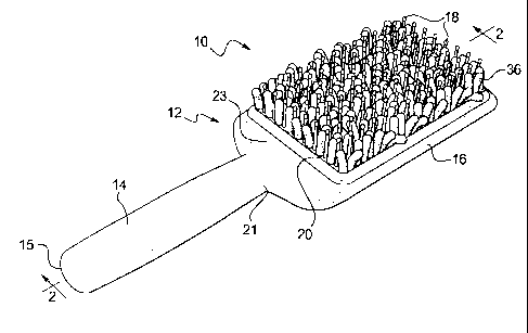
complimentary sized retention tab 1020 protruding from one end. When the foam
block
1003 is placed in the recess 1014 on the back side 1012 of the head 1004, the
retention
tab 1020 seats in the notch 1018 to help retain the foam block 1003 in the
recess 1014
and to assist a user in grasping and removing the water absorbent material
block 1003
therefrom, as needed. The number, size, location, and arrangement of the notch
and
retention tab, or means of retention and release, can vary and remain within
the teachings
of the present invention.
CA 02799255 2012-12-19
[00106] The block 1003 and the bristles 1016 are integrally formed together of
a water
absorbent material such as a small open cell foam. The foam block 1003 can be
integrally formed or molded with the bristles 1016. The foam block 1003 and
bristles
1014 can be made of a foam material having sufficient rigidity to permit the
bristles to
separate and comb through wet hair. The body 1002 of the brush 1000 may be
formed of
one piece or more than one piece fitted together, as with the other examples
described
herein. The body can be made of injection molded plastic. The materials and
arrangement of the body and the foam block can vary and remain within the
teachings of
the present invention. The ability to remove the water absorbent material from
the body
can allow a user to squeeze water from the bristles and block, to allow easy
replacement,
or both. Having the block 1003 exposed will also greatly aid in evaporation of
moisture
from the water absorbent material when not being used, even if still retained
in the recess.
[00107] A hair brush 1100 is shown in Fig. 19 and has a body 1102 with a
handle 1104
extending from a cylindrical head 1106. The body 1102 has a longitudinal axis
V-V.
The handle 1104 is joined to the head 1106 at a neck 1107. The cylindrical
head 1106
has a plurality of oversized bristles 1108. The bristles 1108 are arranged to
extend
radially outward relative to the longitudinal axis V-V. The head 1106 can be
hollow and
can have an open end 1114 opposite the handle end. The bristles 1108 have a
center
element 1110, as shown in Fig. 20, with a coating 1112 of a water absorbent
material.
The center element 1110 of the bristles can be made of nylon or of a material
with similar
qualities for strength and flexibility. The center element 1110 of the
bristles 1100 can be
coated or encased in the water absorbent material layer 1112 such as a small
open cell
foam. The bristles can be individually mounted on the head 1106.
Alternatively, the
water absorbent material layer 1112 can be overmolded onto a plastic or nylon
sleeve
with integral bristles. The brush can include a cylinder base (not shown) for
receiving
such a removably replaceable sleeve.
[00108] Fig. 21 shows another example of a hair brush 1200 according to the
present
invention. The hair brush 1200 has a body 1202 with a bristle face 1204 and a
gripping
face 1206. The body 1202 has an absorbent core or block 1208 and a carrier
1209. The
carrier 1209 can be plastic, wood, metal, or the like and has a support plate
1211 against
which the core or block 1208 rests. The brush 1200 has no separate handle in
this
21
CA 02799255 2012-12-19
example. A plurality of bristles 1210 are mounted on or protrude through the
bristle face
1204. The carrier 1209 has an arc shaped bridge 1212 opposite the bristle face
1204.
The bridge 1212 extends between one end of the body 1202 and the opposite end
of the
body. A midpoint 1214 of the bridge 1212 is spaced apart from a back side of
the plate
1211 to create a space to receive the absorbent core 1208. The absorbent core
1208 is
captured under the bridge 1212 and on the back side of the plate 1211 opposite
the bristle
face 1204. The absorbent core 1208 can be formed of a water absorbent foam
material.
The bridge 1212 can have a grip 1216 disposed at the midpoint 1214 to create a
comfortable hold for the user. One end or the other of the bridge 1212 can be
releasably
attached to one end or the other of the plate 1211 in order to allow the
absorbent core to
be removable and replaceable within the body 1202. A user can release the
bridge 1212
and replace a wet core with a dry core if desired. In one example, the bridge
1212 can be
formed of a material that is sufficiently flexible to allow a user to press
the bridge 1212
toward the plate 1211 to squeeze the absorbent core 1208 to release water.
[00109] The bristles 1210 have a center element (not shown), similar to the
previous
examples, of a non-absorbent, relatively stiff or rigid material, such as
nylon. Each of the
center elements is again coated with a water absorbent foam material such as
shown in
Fig. 20. The foam coating on the bristles 1210 can wick water from the
bristles to the
absorbent core 1208. The bristle face 1204 can have perforations for
attachment of the
bristles 1210 with the foam coating and to allow the foam coating on the
bristles 1210 to
contact the foam core 1208. Such contact between the foam coating and the foam
core
1208 permits water absorbed from wet hair during styling by the bristles 1210
to be
wicked away to the absorbent foam core 1208. The foam core 1208 can be
removable
and can be squeezed, whether removed or not, to release water absorbed by the
core.
The carrier can be constructed so that the core and bristles are formed as one
piece with
the bristles protruding through perforations (not shown) on the support plate.
The open
sides of the carrier 1209 allow water to evaporate and dry the absorbent core
1208.
[00110] In all of the foregoing examples, the brush bodies may be formed or
molded
of plastic such as acrylonitrile butadiene styrene (ABS) or a similar
material. Bristle
materials may include nylon, plastic, natural, stiff animal hair, or other
materials. In
certain examples, the disclosed bristle pad, support, or substrate may be made
of the same
22
CA 02799255 2012-12-19
material as the bristles or of a different material. Such materials can
include plastic
material meeting the requisite requirements for a combination of strength and
flexibility.
1001111 A microfiber fabric according to the present disclosure can include a
base
layer or substrate and fabric or flexible rods made of polyester 85% and nylon
15%.
Other material and chemical combinations may be used if such materials have
the desired
characteristics described above.
[00112] An antimicrobial additive e.g. triclosan may be used with the
microfiber fabric
and/or the absorbent foam material described above to give the disclosed hair
brushes and
styling implements antimicrobial properties.
[00113] The specific features of any one of the embodiments described herein
may be
employed on any of the other embodiments where feasible. For example, any of
the
brush bodies may have a handle or no handle, texture or no texture. Brushes
may have a
water absorbing material of foam, fabric, or other suitable water absorbing
materials.
Suitable fabrics may include and are not limited to various fabric types and
weaves such
as plain weaves, terry cloth, cut or uncut pile weaves, or the like. Any of
the hair brushes
may include coated bristles, separate bristles, integrally molded bristles,
and/or absorbent
rods, etc., and remain within the teachings of the present invention.
[00114] Materials and combinations of materials used for the brushes described
herein
can vary. For example, decorative features may be used on a brush body such as
decorative gripping surfaces with or without texture, combinations of
materials such as
wood and plastic, or overmolded plastics or other materials. Such materials
may be made
in complimentary or contrasting colors and/or textures, or combinations, and
be used on
any of the hair brushes described herein and remain with the teachings of the
present
invention.
[00115] Although certain hairstyling implements have been described herein in
accordance with the teachings of the present disclosure, the scope of coverage
of this
patent is not limited thereto. On the contrary, this patent covers all
examples of the
teachings of the disclosure that fairly fall within the scope of permissible
equivalents.
23