Note: Descriptions are shown in the official language in which they were submitted.
CA 02799496 2016-12-05
CLADDING SYSTEM FOR BUILDING LAMINATES
The present invention relates generally to laminate panels (also called facade
cladding panels) to be applied to the facade of buildings, and specifically
relates to
cladding systems and methods for affixing the laminate panels to building
facades more
efficiently and with less cost.
According to one embodiment, a visible cladding system for attaching laminate
panels onto a building wall is provided. The visible cladding system comprises
at least
one laminate panel support beam to be mounted onto a building wall, wherein
the
laminate panel support beam comprises at least one track. The visible cladding
system
also comprises at least one secondary support beam mounted to the at least one
laminate
panel support beam, at least one sliding clip slidingly coupled to at least
one track, and at
least one laminate panel coupled to at least one sliding clip and thereby
slidable along the
track, wherein the laminate panel is configured to be fastened to the
secondary support
beam.
According to yet another embodiment, a concealed cladding system configured
for attaching laminate panels onto a building wall is provided. The system
comprises at
least two wall brackets horizontally spaced apart, wherein each wall bracket
comprises
an upper attachment component and a lower attachment component. The system
also
comprises at least one intermediate connector coupled to the wall brackets,
wherein the
intermediate connector comprises an upper coupling mechanism, a lower coupling
mechanism, and a hanger member. The upper coupling mechanism of the
intermediate
connector is coupled with the upper attachment component of the wall brackets,
and the
lower attachment component of the intermediate connector is coupled with the
upper
attachment component of the wall bracket. The concealed cladding system also
comprises at least one hanger clip having a laminate panel hanger member
coupled with
the hanger member of the intermediate connector; and a laminate panel fastened
to at
least one of the hanger clips.
The features and advantages of the present invention will become apparent from
the following description and the accompanying drawings.
CA 02799496 2012-11-14
WO 2011/150035 PCT/US2011/037871
-2-
The following detailed description of the embodiments of the present invention
can be best understood when read in conjunction with the following drawings,
where like
structure is indicated with like reference numerals.
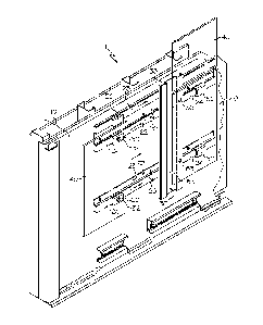
FIG. 1 is a perspective view of a visible cladding attachment system according
to
one or more embodiments of the present invention.
FIG. 2A is a horizontal cross-sectional view of a visible cladding attachment
system according to one or more embodiments of the present invention.
FIG. 2B is an exploded cross-sectional view of a visible cladding attachment
system according to one or more embodiments of the present invention.
FIG. 3 is a perspective view of a concealed cladding attachment system
according
to one or more embodiments of the present invention.
FIG. 4A is a horizontal cross-sectional view of a concealed cladding
attachment
system according to one or more embodiments of the present invention.
FIG. 4B is an exploded cross-sectional view of a concealed cladding attachment
system according to one or more embodiments of the present invention.
FIG. 4C is a horizontal cross-sectional view of another concealed cladding
attachment system according to one or more embodiments of the present
invention.
FIG. 4D is a horizontal cross-sectional view of yet another concealed cladding
attachment system according to one or more embodiments of the present
invention.
Referring to FIGS. 1, 2A and 2B, a visible system 1 for fastening laminate
panels
40 onto a building wall 10 is provided. As stated above, this system 1 is
considered a
visible cladding attachment system, because the cladding fastener component(s)
32 are
not hidden behind the laminate panels 40. As used herein, the building wall 10
may
comprise many suitable structures familiar to one of ordinary skill in the
art, such as a
stud wall, exterior sheathing, a jam flashing membrane, a water resistive
barrier,
insulation, or any other building or foundation structure.
Referring again to FIGS. 1, 2A and 2B, the system 1 comprises at least one
laminate panel support beam 20, 25 mounted onto the building wall 10, wherein
the
laminate panel support beam 20, 25 comprises at least one track 24. In the
embodiment
of FIGS. 1, 2A and 2B, the laminate panel support beam 20 may be mounted
directly
onto the building wall 10 or may be coupled to an additional mounting
structure (not
shown) mounted on the building wall 10. Also, while the present discussion
centers on a
CA 02799496 2012-11-14
WO 2011/150035 PCT/US2011/037871
-3-
laminate panel support beam 20, 25 having a horizontal configuration, is it
contemplated
that the laminate panel support beam 20, 25 could be positioned vertically or
diagonally
if required by the structure and/or contours of the building wall 10.
Referring again to the embodiment shown in FIGS. 1, 2A-B, the laminate panel
support beam 20 may comprise two spaced parallel tracks 24. In this
embodiment, the
laminate panel support beam 20 may define a W-shape configuration wherein the
tracks
24 constitute raised portions of the laminate panel support beam 20, and the
portion
between the tracks 24 is a non-raised beam 23 that abuts a building wall 10.
As shown,
the laminate panel support beam 20 of FIGS. 1, 2A-B may be mounted onto the
building
wall 10 via one or more fasteners 22. Many fasteners are contemplated herein,
for
example, screws, bolts, nails, or combinations thereof. The fasteners 22 may
comprise
any suitable rigid material, for example, metals or metal alloys such as
stainless steel,
aluminum, or combinations thereof.
In an alternative embodiment as shown in FIG. 1, the laminate panel support
beam
25 may comprise one track 24. In this embodiment, the laminate panel support
beam 25
may define a J-shape configuration wherein the track 24 is a raised portion of
the
laminate panel support beam 25. In the J-shape configuration, the nonraised
portion
adjacent the track 24 contacts the building wall 10, and is fastened to the
building wall
10 with a fastener 22. As shown in FIG. 1, the laminate panel support beam 25
of FIG. 1
may be mounted onto the building wall 10 via one or more fasteners 22. Further
as
shown, the one track laminate panel support beam 25 may be mounted on the
building
wall 10 proximate a two track laminate panel support beam 20. While the
depicted
laminate panel support beams 20 and 25 are depicted as having one or two
tracks and a J-
shaped or W-shaped geometry, other structures and configurations are
contemplated
herein.
Referring to FIG. 1, the system 1 may also comprise at least one secondary
support beam 50 oriented generally perpendicular to the laminate panel support
beam 20,
25 and mounted to at least one laminate panel support beam 20, 25. While the
present
discussion centers on secondary support beams 50 having a vertical
configuration, is it
contemplated that the secondary support beam 50 could be positioned
horizontally or
diagonally if required by the structure and/or contours of the building wall
10. As shown
in the embodiment of FIG. 1, the secondary support beam 50 may be mounted to
two
CA 02799496 2012-11-14
WO 2011/150035 PCT/US2011/037871
-4-
laminate panel support beams 20, 25. It is also alternatively contemplated
that the
secondary support beam 50 may be coupled to less than two or more than two
laminate
panel support beams 20, 25. Moreover, it is also contemplated that the
secondary support
beam 50 may also define various structural shapes and structural profiles. As
shown in
the embodiment of FIG. 1, the secondary support beam 50 may comprise a pair of
parallel raised beams 52 connected by a nonraised beam 53 disposed
therebetween. As
an alternative to this raised/nonraised profile, other embodiments may include
a flat
profile.
Referring again to FIGS. 1, 2A and 2B, the system 1 may also comprise at least
one sliding clip 30 that is configured for attaching laminate panels 40 to the
laminate
panel support beams 20, 25. The sliding clips 30 may be slidingly coupled to
track 24,
and are also attached to one or more laminate panels 40, which are moveable
with the
sliding clips 30. As shown in FIGS. 1, 2A and 2B, the system 1 may comprise
two
sliding clips 30 slidingly coupled to the two spaced tracks 24 of the two
track laminate
panel support beam 20, as well as a sliding clip 30 slidingly coupled to the
one track
laminate panel support beam 25. While the FIGS depict only one sliding clip 30
per
track, it is contemplated to have multiple sliding clips 30 on each track 24.
Referring yet again to FIGS. 1, 2A, and 2B, the two track laminate panel
support
beam 20 may comprise two laminate panels 40 coupled thereto. In another
embodiment
as shown, the laminate panel 40 may be coupled at one end to a sliding clip 30
attached
to a track on the two track lateral support beam 20, and coupled at an
opposite end to a
sliding clip 30 on the one track laminate panel support beam 25. The laminate
panel 40
may be coupled to the sliding clip 30 via a fastening component 32. The
fastening
component 32 is a bolt, a screw, or any other suitable fastener. The fastening
component
32 may comprise a rigid material, for example, aluminum, stainless steel, or
combinations thereof.
When mounting the laminate panel 40 onto the laminate panel support beam 20,
various assembly sequences are contemplated. For example, the sliding clip(s)
30 may
first be moved along the track(s) 24 to the desired position on the laminate
panel support
beam 20, 25, at which point, the laminate panel 40 is then attached to the
sliding clip 30.
Alternatively as shown in FIG. 1, the sliding clip(s) 30 is first attached to
the laminate
panel 40, then the sliding clip(s) 30 and attached laminate panel 40 may be
slidingly
CA 02799496 2012-11-14
WO 2011/150035 PCT/US2011/037871
-5-
moved along the track(s) 24 to the desired position on the laminate panel
support beams
20, 25. In essence, the laminate panel 40 may be coupled to one or more of the
sliding
clips 30 before or after the sliding clips 30 are coupled to the tracks 24 of
the laminate
panel support beam 20. After the laminate panel 40 is positioned at the
desired position
on the building wall 10, the laminate panel 40 may then be secured to the
secondary
support beam 50 by means of a fastener 55. Like the other fasteners described
above, the
fastening component 55 may comprise a bolt, screw, or another suitable
fastening
component known to one of ordinary skill in the art. Without being bound by
theory, the
sliding functionality of the track 24 and clip 30 assembly enables the
laminate panel 40
to be quickly attached to the facade of a building, or quickly removed,
thereby reducing
labor costs.
Various materials and compositions are contemplated for the visible system 1.
In
one embodiment, the laminate panel 40 may be a phenolic resin based material.
A
suitable commercial embodiment for the laminate panel 40 is the VIVIXTM
laminate
produced by Formica . The laminate panel support beam 20, the sliding clip 30,
and the
secondary support beam 50 may all comprise rigid support material, for
example, a
metal, a metal alloy, or combinations thereof. In exemplary embodiments, these
rigid
support materials may be selected from the group consisting of aluminum,
stainless steel,
or combinations thereof.
In a further embodiment as shown in FIGS. 2A-B, the system 1 may also comprise
a joint closure 60 disposed between sliding clips 30 on adjacent yet separated
laminate
panels 40. The joint closure 60 is positioned to block the opening between the
adjacent
yet separated panels 40. The joint closure 60, as shown in FIG. 2A, defines a
C-shape
adapted for the joint closure 60 to fit snugly between a pair of sliding clips
30; however
other geometries are contemplated herein. While many materials are
contemplated for
the joint closure 60, the joint closure 60 may comprise a rigid metal material
such as
aluminum or stainless steel.
Referring to FIGS. 3 and 4A-4D, a concealed cladding attachment system 100 for
fastening laminate panels 40 onto a building wall 10 is provided. In contrast
to the
visible system 1, this system 100 is considered a concealed cladding
attachment system,
because the support attachments are disposed behind the laminate panels 40.
Referring to
FIG. 3, the system 100 may comprise at least two wall brackets 130
horizontally spaced
CA 02799496 2012-11-14
WO 2011/150035 PCT/US2011/037871
-6-
apart and attached to vertical beams 120 supported by the building wall 10 as
shown in
FIGS. 3, 4A, and 4B, or mounted directly to the building wall 10 as shown in
FIGS. 4C
and 4D. As shown in FIGS. 4A and 4B, the vertical beams 120 may be mounted
onto the
building wall 10 via a fastener 122 (e.g., a bolt, a screw, etc).
Various geometries and structures are contemplated for the wall bracket 130.
As
shown in FIGS. 4A-B, wall bracket 30 may define an L-shaped cross-sectional
profile
comprising a vertical portion 137 attached to vertical beams 120 and a
horizontal portion
132 extending perpendicularly from the bottom of the vertical portion 137. The
vertical
portion 137 is attached to the vertical beams 120 via fasteners 131, such as
screws or
bolts. In one embodiment, the horizontal portion 132 of the wall bracket 130
is
configured to extend the distance of a cavity 80 between the laminate panel 40
and the
vertical beams 120. As shown, the cavity 80 enables water drainage and air
flow 90 in
the concealed cladding attachment system 100, or the visible cladding
attachment system
1. As an alternative to the L-configuration of FIG. 4A and 4B, referring to
FIG. 4C, the
vertical portion 137 is attached to an outer surface of a building wall 10;
however, the
wall bracket 130 comprises a horizontal portion 132 and/or a horizontal arm
133 that
extends behind the vertical portion 137 and at least partially through a
building wall 10
or insulation 11.
Moreover, as shown in FIG. 4D, the wall bracket 130 may comprise a pair of
spaced parallel vertical portions 137a, 137b. As shown in the embodiment of
FIG. 4D,
one of the vertical portions 137b may be disposed inside the insulation 11 of
the building
wall 10, whereas the other vertical portion 137a may contact a surface of the
building
wall 10. In this embodiment, the horizontal portion 132 of the wall bracket is
parallel to
the horizontal arm 133 of the upper attachment component 134. As shown, the
horizontal
portion 132 and the horizontal arm 133 extend perpendicular between the
vertical
portions 137a and 137b. Moreover as shown in FIG. 4D, the horizontal portion
132 and
the horizontal arm 133 also extend beyond the distance 95 between the parallel
vertical
portions 137a, 137b. For example, the horizontal portion 132 and the
horizontal arm 133
may extend the length of the insulation 11.
Further as shown in FIGS. 4A-B, the wall bracket 130 may comprise an upper
attachment component 134 and a lower attachment component 136 for coupling
with the
intermediate connector 140, as described in detail below. The lower attachment
CA 02799496 2012-11-14
WO 2011/150035 PCT/US2011/037871
-7-
component 136 is attached to a horizontal arm 138 extending from the vertical
portion
137 at a position above and parallel to the horizontal portion 132 of the wall
bracket 130.
In one embodiment, the lower attachment component 136 may be a protrusion
configured to interlock with a corresponding protrusion of the lower coupling
mechanism 144 of the intermediate connector 140. The upper attachment
component 134
may comprise a hook insertable into a receptacle, 142, i.e., the upper
coupling
mechanism 142 as described in further detail below. As shown in FIGS. 4A and
4B, the
hook of the upper attachment component 134 is attached to another horizontal
arm 133
extending from the vertical portion 137 of the wall bracket 130. Various other
suitable
structural components are contemplated for the upper attachment component 134
and the
lower attachment component 136.
Referring again to FIGS. 3, and 4A-4D, the system 100 also comprises at least
one
intermediate connector 140 coupled to the wall bracket 130. The intermediate
connector
140 comprises an upper coupling mechanism 142 configured to be coupled with
the
upper attachment component 134 of the wall bracket 130. In one embodiment, the
intermediate connector 140 may matingly couple with the upper attachment
component
134 of the wall bracket 130. For example as shown in FIGS. 4A-4D, the upper
coupling
mechanism 142 may comprise a receptacle 142 that receives the hook 134 of the
wall
bracket 130.
As shown in FIGS. 3 and 4B, the intermediate connector 140 also comprises a
lower coupling mechanism 144 configured to couple with the lower attachment
component 136 of the wall bracket 130. In one embodiment, the lower coupling
mechanism may interlockingly couple with the lower attachment component 136.
As
shown, the lower attachment component 136 of the intermediate connector 140 is
a
protrusion, which causes the lower attachment component 136 of the wall
bracket 130 to
deflect inwardly to facilitate the interlocking coupling arrangement. When
attaching the
intermediate connector 140 to the wall bracket 130, the intermediate connector
140 is
rotated such that the receptacle 142 attaches to the hook 134, then the
intermediate
connector 140 is further rotated such that the lower coupling mechanism 144
(e.g., the
protrusion 144) deflects the lower attachment component 136 (e.g., the
protrusion 136)
inwardly.
CA 02799496 2012-11-14
WO 2011/150035
PCT/US2011/037871
-8-
Having multiple connections between the wall bracket 130 and the intermediate
connector 140 as described above helps ensure the wall bracket 130 is secured
to the
intermediate connector 140. That being said, the system 100 may also comprise
a
bumper 135 or extension coupled to the horizontal arm 133 of the wall bracket
130,
which is configured to engage an inward section 143 of the intermediate
connector 140
to further secure the intermediate connector 140 on the wall bracket 130.
Further as shown in FIGS. 3, 4A, and 4B, the intermediate connector 140 also
comprises an intermediate hanger member 146 used for coupling with the
laminate panel
hanger member 151 of the hanger clip 150. Referring to FIGS. 3, and 4A-B, the
hanger
clips 150, which join the laminate panel 40 to the intermediate connector 140,
utilize
their respective laminate panel hanger member 151 to matingly couple with the
intermediate hanger member 146 of the intermediate connector 140. Specifically
as
shown, the intermediate hanger member 146 is nested within the laminate panel
hanger
member 151.
When attaching the laminate panel 40 in the system 100 of the present
invention,
various assembly sequences are contemplated. Specifically, the hanger clips
150 may be
coupled to the laminate panels 40 prior to the attachment of the hanger
clip(s) 150 to the
intermediate connector(s) 140. In an alternative embodiment, it is
contemplated that the
hanger clip(s) 150 may be attached to the intermediate connector(s) 140 prior
to the
laminate panels 40 being attached to the hanger clips 150. The hanger clip 150
may be
attached to the laminate panel 40 via any suitable fastener 155, such as a
screw or bolt.
The hanger clip 150 comprises additional components which ensure that the
hanger clip 150 is securely attached to the intermediate connector 140. As
shown in
FIGS. 4A-4B, the hanger clip 150 may comprise an adjustable bolt 156, which
may be
adjusted to engage the upper surface 145 of the intermediate connector 140 to
stabilize
the hanger clip 150 on the intermediate connector 140. In a specific
embodiment, the
hanger clip 150 is manufactured and packaged with the adjustable bolt 156 and
nut 157
attached, wherein the nut 157 is disposed in a slot 152 of the hanger clip
150. Packaging
the adjustable bolt 156 and nut 157 with the hanger clip 150 eliminates the
need for the
consumer to purchase a separate fastener to secure the hanger clip 150 to the
intermediate connector 140.
CA 02799496 2012-11-14
WO 2011/150035 PCT/US2011/037871
-9-
In further embodiments as shown in FIGS. 4A-B, the hanger clip 150 may also
comprise a flexible cushioning component 160, which engages a surface 141 of
the
intermediate connector 140 to stabilize the hanger clip 150 on the
intermediate connector
140. As shown, the flexible cushioning component 160, which may be embedded in
the
hanger clip 150, has a flexible tip, which deflects upon engaging surface 141
of the
intermediate connector 140. By engaging the intermediate connector 140, the
flexible
cushioning component 160 helps prevent the intermediate connector 140 or
hanger clip
150 from moving relative to each other, thereby further securing the hanger
clip 150 on
the intermediate connector 140. The flexible cushioning component 160 may
comprise
any suitable flexible material, for example, a flexible polymeric
nondegradable material
such as polyurethane, santopreneTM, other thermoplastic elastomers, or
combinations
thereof
In further embodiments as shown in FIGS. 4A-B, the hanger clip 150 may also
comprises recessed reservoir portions 153, 154 operable to collect condensed
water. The
recessed reservoir portions 153, 154 may be sloped to facilitate the removal
of
condensate present on the recessed reservoir portions 153, 154 of the hanging
clip 150.
Similar to the visible cladding system 1, the concealed cladding attachment
system 100
may also comprise a joint closure 170 coupled to the wall bracket 130 via
fastener 174.
As shown in FIGS. 4A-B, the joint closure 170 is configured to block the
opening
between adjacent yet separated laminate panels 40. Similar to the recessed
reservoir
portions 153, 154 of the hanger clip 150, the joint closure 60 comprises a
lower lip 172
operable to collect and remove water.
Moreover, it is contemplated to use various additional structural components
for
the cladding systems depending on the needs of the builder. For example,
pieces with
different shapes and curvatures may be specifically developed for the contours
or corners
of the building wall 10.
It is further noted that terms like "preferably," "generally", "commonly," and
"typically" are not utilized herein to limit the scope of the claimed
invention or to imply
that certain features are critical, essential, or even important to the
structure or function
of the claimed invention. Rather, these terms are merely intended to highlight
alternative
or additional features that may or may not be utilized in a particular
embodiment of the
present invention.
CA 02799496 2012-11-14
WO 2011/150035 PCT/US2011/037871
-10-
For the purposes of describing and defining the present invention it is
additionally
noted that the term "substantially" is utilized herein to represent the
inherent degree of
uncertainty that may be attributed to any quantitative comparison, value,
measurement,
or other representation. The term "substantially" is also utilized herein to
represent the
degree by which a quantitative representation may vary from a stated reference
without
resulting in a change in the basic function of the subject matter at issue.
Having described the invention in detail and by reference to specific
embodiments
thereof, it will be apparent that modifications and variations are possible
without
departing from the scope of the invention defined in the appended claims. More
specifically, although some aspects of the present invention are identified
herein as
preferred or particularly advantageous, it is contemplated that the present
invention is not
necessarily limited to these preferred aspects of the invention.