Note: Descriptions are shown in the official language in which they were submitted.
CA 02799703 2012-11-16
DESCRIPTION
NDNOSCOPIC 3D WAGE PHOTOGRAPHING DEVICE AND 3D
CAMERA
Technical Field
The present invention relates, in general, to a
device for producing a 3D image that can be viewed without
three-dimensional glasses using an existing monoscopic lens
and a 3D camera and, more particularly, to a 3D image
photographing device and a 3D camera, in which an existing
monoscopic camera photographs a front subject while rotating
360 degrees toward the subject to allow an image to be
photographed at various angles on respective frames, thus
enabling the brain to recognize a 3D image with the naked eye
without having to wear three-dimensional glasses.
Background Art
Generally, until now, a device or camera capable of
photographing a 3D image has not used a monoscopic device
or camera but has used a binocular device or camera. Even
if the monoscopic device or camera is used, the 3D image
photographing device or camera requires three-dimensional
glasses when viewing the 3D image. Further, since a mirror,
a prism or a half mirror should be used in front of a lens
of the camera, the configuration of the above device or
camera is complicated and inconvenient.
1
CA 02799703 2012-11-16
The prior art is problematic in that it suffers
difficulty in dividing an image into left and right images
at the time of being photographed and also three-
dimensional glasses are required to view the image.
Moreover, a method using two cameras and a method of
installing a separate mirror or prism in front of the
existing camera are problematic in that it is difficult to
reduce the depth of left and right images by the space of
an interval between the two eyes of a person due to the
size of the camera lens itself, so that the depth of the
left and right images is excessively increased, thus
causing eyestrain and dizziness. In order to reduce the
depth of the left and right images, an orthogonal type is
used. However, this also uses a half mirror, so that
incident light is reduced by halves, and thus the picture
quality may be deteriorated. Such a binocular 3D image
photographing device or camera is problematic in that it is
difficult to keep the picture qualities of the images
incident to two cameras constant, and it also being
difficult to identically match the zoom functions of the
two cameras.
Disclosure
Technical Problem
Accordingly, the present invention provides a 3D
image photographing device and a 3D camera for
photographing a 3D image which can be viewed without three-
2
CA 02799703 2012-11-16
dimensional glasses using an existing monoscopic camera. In
other words, an object of the present invention is to
provide a monoscopic 3D image photographing device and a
monoscopic 3D camera, in which no device or tool is
installed in front of a lens of the monoscopic camera with
one lens, and the 3D image is photographed in a multi-view
photographing manner by rotating the camera lens 360
degrees, thus photographing the 3D image that can be viewed
with the naked eye without using the glasses.
Technical Solution
In order to accomplish the above object, the present
invention provides a 3D image photographing device and a 3D
camera for photographing a 3D image that can be viewed with
the naked eye without using three-dimensional glasses, in
the same picture quality as a 2D image. The invention is
characterized in that no tool is installed in front of a
camera lens, and the camera lens photographs an image while
rotating 360 degrees toward a front subject, thus allowing
the 3D image to be photographed in the same picture quality
as when photographing the 2D image. Further, it is possible
to adjust the diameter of a rotary connecting bar equipped
with the camera lens so as to reduce or increase the
rotational width of the camera lens as desired, thus
reducing the horizontal and vertical depths of the 3D image
as desired and thereby overcoming eyestrain and dizziness
that may be caused when viewing the 3D image.
3
CA 02799703 2012-11-16
Advantageous Effects
The present invention is advantageous in that it
solves the problems of the existing binocular 3D image
photographing device, that is, a difference in color
between left and right images and the difficulty of
simultaneously photographing the left and right images. It
can also solve the unclear picture quality unlike the 2D
image and the problem of requiring three-dimensional
glasses when viewing a 3D image. Further, the invention
allows the rotational width of the camera lens to be
reduced as desired while photographing the 3D image with
the same quantity of incident light as when photographing
the 2D image, thus enabling the depth of horizontal and
vertical images to be reduced as desired, and being capable
of photographing the 3D image that has the same picture
quality and brightness as the 2D image, thereby overcoming
eyestrain and dizziness. Furthermore, since three-
dimensional glasses are not required, the invention is
economical, and since it is possible to enjoy the 3D image
with an existing display without the necessity of
purchasing a special display or monitor, the present
invention is advantageous in terms of preserving the
environment and conserving energy. Since there is no
problem of the left and right images being reversed, it is
convenient to photograph the 3D image. Further, even when
editing the image, a special method is not required, so
4
CA 02799703 2012-11-16
that an existing editing technology and editor can be
utilized without being modified, and thus the invention is
very economical.
Description of Drawings
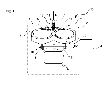
FIG. 1 is a view showing a configuration of a
monoscopic 3D image photographing device, in which a camera
is mounted to a rotary connecting bar connecting two rotary
tracks of the same size;
FIG. 2 is a sectional view of the monoscopic 3D image
photographing device shown in FIG. 1;
FIG. 3 is a view illustrating the rotation of the
camera mounted to the rotary connecting bar connecting the
two rotary tracks of the monoscopic 3D image photographing
device of FIG. 1;
FIG. 4 is a view illustrating the movement of a
connecting pin of the rotary connecting bar to pairs of
rotary tracks of different sizes, in the monoscopic 3D
image photographing device having several pairs of rotary
tracks of different sizes;
FIG. 5 is a view showing a configuration of a
monoscopic 3D camera containing the 3D image photographing
device in which a rotary connecting bar equipped with a
camera lens rotates on two rotary tracks of the same size;
and
FIG. 6 is a view illustrating a monoscopic 3D camera
that photographs a front subject in a 3D manner while a
5
CA 02799703 2012-11-16
lens of the camera is rotated at 360 degrees merely by one
rotary track.
Best Mode
The present invention will be described in detail
with reference to the accompanying drawings.
FIG. 1 is a view showing the configuration of a 3D
image photographing device 70. This device is configured so
that a rotary connecting bar 2 equipped with a camera 1 by
a camera support 4 is connected to two rotary tracks 7 and
7' via connecting pins 3 and 3', and a shaft 9 of a motor 11
is connected to two shafts 10 and 10' of the two rotary
tracks 7 and 7' via a rotary belt 8. Thus, when the
rotating shaft 9 of the motor 11 rotates, a lens 12 of the
camera 1 rotates 360 degrees toward a front subject to
photograph a 3D image. The image can be seen by a
viewfinder 6 with a lead 5 or a wireless viewfinder.
If the rotating shaft 9 of the motor 11 rotates, the
two rotating shafts 10 and 10' and the two rotary tracks 7
and 7' are rotated by the rotary belt 8. Simultaneously,
the rotary connecting bar 2 connected to the left rotary
track 7 and the right rotary track 7' by the connecting
pins 3 and 3' is also rotated. Also, the camera 1 mounted
to the rotary connecting bar 2 by the camera support 4
rotates 360 degrees, so that incident light L of the front
subject is incident on the camera lens 12 in multi-views
and thus the image is photographed on respective frames 18
6
CA 02799703 2012-11-16
at various angles. As a result, a 3D image that can be
recognized by the brain is photographed. When the lens 12
of the camera 1 mounted to the rotary connecting bar 2
rotates 360 degrees toward the subject once per second,
images L of different angles that are photographed while
the lens rotates 360 degrees per second are incident into
every frame. Thus, the images of various angles of
respective frames are synthesized in the brain, thus
allowing the synthesized images to be viewed as a 3D image.
If the camera 1 is rotated by only one rotary track
that is directly connected to the rotating shaft 9 of the
motor 11 without the rotary connecting bar 2, the lens 12
of the camera 1 is turned upside down during the rotation
of the camera, an inverse image and an erect image may be
alternately incident as the camera rotates. However, the
present invention solves such a problem. Thus, the lens 12
of the camera 1 is rotated 360 degrees by the rotary
connecting bar 2 connected to one pair of rotary tracks 7
and 7' that have the same size and are simultaneously
rotated at the same speed by the same motor 11, so that the
camera 1 and the lens 12 are always kept erect even during
the rotation, thus preventing the image L from being
flipped. Hence, the present invention provides the 3D image
photographing device 70 that can photograph the 3D image
using an existing general 2D camera.
FIG. 2 is a sectional view showing the 3D image
photographing device 70 of FIG. 1. Referring to the
7
CA 02799703 2012-11-16
drawing, as the two rotating shafts 10 and 10' are
rotatably connected to the rotating shaft 9 of the motor 11
by the rotary belt 8, the two rotary tracks 7 and 7' are
rotated and simultaneously the rotary connecting bar 2
connected to the rotary tracks 7 and 7' by the connecting
pins 3 and 3' is also rotated. Further, the camera 1 and
the lens 12 mounted to the rotary connecting bar 2 rotate
while being kept erect.
FIG. 3 shows a state 80 wherein the rotary connecting
bar 2 equipped with the camera 1 is connected to the rotary
tracks 7 and 7' by the connecting pins 3 and 3' and is
rotated on the rotary tracks 7 and 7'. When the rotating
shaft 9 of the motor 11 rotates and thus both the rotating
shafts 10 and 10' are rotated by the rotary belt 8, the
rotary connecting bar 2 connecting the two rotary tracks 7
and 7' to each other also rotates. The drawing illustrates
the state wherein the rotary connecting bar 2 rotates in
the direction 2' of 9 o'clock, the direction 22' of 6
o'clock and the direction 32' of 3 o'clock. In order to
prevent the image of the incident light L entering the lens
12 of the camera 1 from being turned upside down during the
rotation, the rotary connecting bar 2 connected to the two
rotary tracks 7 and 7' of the same rotational width rotates
while maintaining the vertical and horizontal states even
during the rotation, thus preventing the image L from being
flipped when the lens 12 of the camera 1 mounted to the
rotary connecting bar 2 photographs the front subject while
8
CA 02799703 2012-11-16
rotating 360 degrees.
FIG. 4 shows the state 90 wherein the connecting pins
3 and 3' of the rotary connecting bar 2 are freely movable
to a first pair of connecting pins 33 and 33', a second
pair of connecting pins 43 and 43' and a third pair of
connecting pins 53 and 53' while sliding on the rotary
connecting bar 2. As the connecting pins 3 and 3' of the
rotary connecting bar 2 move from the pair of rotary tracks
located at an outer position to the pair of rotary tracks
53 and 53' located at the innermost position, the
rotational width of the lens 12 of the camera 1 is reduced.
In other words, as the pair of connecting pins 3 and 3'
moves from the leftmost rotary tracks to the rightmost
rotary tracks 53 and 53', the rotational width of the
camera 1 is gradually reduced, so that a depth of the image
L photographed on each image frame 18 becomes gradually
narrower. Accordingly, the three-dimensional effect of the
3D image can be adjusted and moreover it is possible to
reduce eyestrain and dizziness that may be experienced when
looking at the 3D image.
FIG. 5 shows an embodiment of the 3D camera 100 in
which the 3D image photographing device 70 of FIG. 1 is
embedded. That is, since the 3D image photographing device
70 of FIG. 1 is embedded in the 3D camera 100, the camera
lens 12 photographs the image L while rotating 360 degrees
toward the front subject. Further, the 3D image
photographing camera 100 photographs the image L in multi-
9
CA 02799703 2012-11-16
views on every frame 18 to allow the brain to recognize the
3D image. If the rotating shaft 9 of the motor 11 installed
in the camera rotates, the left and right rotating shafts
and 10' and the left and right rotary tracks 7 and 7'
5 are rotated by the rotary belt 8, the rotary connecting bar
2 connected to one pair of rotary tracks 7 and 7' having
the same rotational width is also rotated, and the camera
lens 12 mounted to the rotary connecting bar 2 via the lens
support 4' also rotates 360 degrees, thus photographing the
10 image L of the front subject in the 3D image of multi-
views. The connecting pins 3 and 3' connecting the rotary
connecting bar 2 with the rotary tracks 7 and 7' slide on
the rotary connecting bar 2 such that the connecting pins
may move to the first pair of rotary tracks 33 and 33', the
second pair of rotary tracks 43 and 43', and the third pair
of rotary tracks 53 and 53', the rotational widths of which
are gradually reduced. Therefore, it is possible to
photograph the 3D image by adjusting the depth of the image
L incident into every frame 18 with the movement of the
connecting pins 3 and 3' on the rotary connecting bar 2
while viewing the photographed 3D image through the
viewfinder 6.
FIG. 6 shows a new embodiment of a 3D camera 110, in
which the lens 12 of the camera rotating 360 degrees by one
rotary track 77 directly connected to the rotating shaft 9
of the motor 11 photographs the image L on every frame 18
in multi-views toward the front subject, thus allowing the
CA 02799703 2012-11-16
brain to recognize the 3D image. In other words, if the
rotating shaft 9 of the motor 11 installed in the 3D camera
110 rotates, the rotary track 77 and the camera lens 12 on
the rotary track rotate 360 degrees in the direction 12' of
10:30, the direction 13' of 9 o'clock, the direction 14' of
7:30, the direction 15' of 4:30, the direction 16' of 3
o'clock, and the direction 17' of 1:30 to photograph the
image L of the front subject at various angles and thereby
allow the image L to be incident at various angles on
several frames. In this way, the 3D camera 110 is
implemented to photograph the 3D image that can be
recognized in 3D by the brain. The camera lens 12 on the
rotary track 77 is allowed to move to a rotary track 88
located at the inner position and a rotary track 99 having
a smaller rotational width, so that it is possible to
photograph the 3D image while viewing the 3D image through
the viewfinder 6 and adjusting the depth of the 3D image.
The 3D camera 110 according to the embodiment of FIG. 6
enables the image L to be photographed in the erect state
even if the camera lens 12 is turned upside down, so that
the 3D image can be photographed even by the camera lens 12
on one rotary track 77, 88, 99 that is directly connected
to the rotating shaft 9 of the motor 11. That is, there is
provided the 3D camera 110 that has a circuit 19 recording
the image L in the erect state even if the lens is turned
upside down.
11