Note: Descriptions are shown in the official language in which they were submitted.
CA 02799853 2015-01-15
CONVERTIBLE TRAILER
Field of the Invention
This invention relates to the field of convertible trailers, and in
particular, to a
convertible trailer system allowing hybrid flexibility for loading different
loads on different
segments of the trailer and tractor trailer combination.
Background of the Invention
In the prior art applicant is aware of United States patent number 6,497,541
which issued December 24, 2002 to Pawluk for a Convertible Vehicle
Transporting Trailer, the
entirety of which is incorporated herein by reference. In United States patent
number 6,497,541
Pawlulc teaches a convertible vehicle transporting trailer has rigid upper and
lower decks. The
upper deck is mounted onto the lower deck by selectively actuable, releasably
lockable
telescopic stanchions. The stanchions are actuable by actuators so as to raise
and lower the
upper deck over the lower deck between a lowered position, an intermediately
elevated
position, and a fully elevated position. In the fully extended position the
upper deck is elevated
above the lower deck so as to allow loading of vehicles or freight onto the
lower deck. In the
intermediately elevated position the upper deck is below the fully elevated
position so as to be
snugly adjacent uppermost extremities of the vehicles or freight on the lower
deck. In the
lowered position the upper deck rests on a mid-section of the lower deck and
on elevated
wheel-wells of the lower deck, so that a mid-section of the upper deck is
between the wheel-
wells of the lower deck and a forward elevated section of the lower deck so as
to be
immediately above and resting on the mid-section of the lower deck.
1
CA 02799853 2015-09-10
Summary of the Invention
The present invention is a convertible trailer system which in one embodiment
includes a stinger steer convertible trailer and a head ramp mounted to a
truck.
The trailer has a segmented lower deck, and a segmented upper deck mounted
onto the lower deck by selectively actuable telescopic stanchions. The
stanchions are actuable
by actuators so as to raise and lower the upper deck between a lowered
position, an
intermediately elevated position, and a fully elevated position. In the fully
elevated position the
upper deck is elevated above the lower deck so as to allow loading of vehicles
or freight onto
the lower deck. In the intermediately elevated position the upper deck is
below the fully
elevated position so as to be snugly adjacent uppel _______________________
most extremities of the vehicles or freight on
the lower deck. In the lowered position the upper deck rests on a mid-section
adjacent an
elevated wheel-wells portion of the lower deck. The upper deck may be
horizontal, or the
forward and rear portions may be inclined downwardly.
The trailer may include a spaced apart longitudinally extending parallel pair
of
side rails. The segmented lower deck includes a forward portion having front
and rear floating
belly portions forward of the mid-section. By way of example, the front and
rear floating belly
portions may be floating belly front and rear ramps as better described below.
The floating
belly portions are independently actuable so that they may be selectively
raised and lowered
relative to the pair of side rails. The floating belly portions are lowerable
to a lower extremity
between the pair of side rails substantially entirely below uppermost edges of
the pair of side
rails. The floating belly portions are elevatable so as to be co-planar with
or above the
uppermost edges of the side rails whereby freight is loadable laterally, that
is, sideways onto the
floating belly portions over the pair of side rails.
C2300834 DOCX;1 2
CA 02799853 2015-09-10
The rear floating belly portion is interposed between the front floating belly
portion and the mid-section of the lower deck. The rear floating belly portion
is also
independently actuable independently of the front floating belly portion, so
as to be selectively
inclined relative to the pair of side rails.
The head ramp has a lower deck and an upper deck mounted thereover. The
head ramp upper deck has a vertical actuator for vertically selectively
actuating the head ramp
upper deck. An over-cab platform is mounted over the cab of a truck. The head
ramp upper
deck is elevatable into a fully raised position substantially horizontally
aligned with the over-
cab platform of the truck. The head ramp upper deck is positionable between a
fully lowered
position and the fully elevated position while remaining substantially
horizontal. The head
ramp upper and lower decks are stacked one over the other and extend
rearwardly of the over-
cab platform so that the reaimost ends of the head ramps upper and lower decks
extend
cantilevered over a hitch of the truck.
Bridging members are mounted so as to cooperate between the rearmost ends of
the head ramp upper and lower decks and the forward-most ends of the trailer
upper and lower
decks to bridge between the upper and lower decks of the head ramp and trailer
respectively
when the upper decks of the head ramp and the trailer are substantially
horizontally aligned or
when the lower decks of the head ramp and the trailer are substantially
horizontally aligned.
The trailer further includes a hitch coupling extending forwardly from the
trailer
so as to engage and mate with the hitch on the truck. Advantageously the over-
cab platform is
inclinable from the horizontal so as to selectively raise and lower a rear end
of the over-cab
platform.
Advantageously the rear floating belly portion is extendable in length between
the mid-section of the trailer and the front floating belly portion so as to
lengthen when forming
C2300834.DOCX,1 3
CA 02799853 2015-09-10
an inclined ramp between the mid-section and the front floating belly portion.
In one
embodiment not-intended to be limiting the floating rear segment is
telescopically extendable.
The segmented upper and lower decks include a pair of wheel-engaging
members. The wheel-engaging members are parallel and laterally spaced apart
and wherein the
pair of wheel-engaging members are adjacent to the side rails so as to form a
longitudinally
extending central opening between the pair of wheel-engaging members. The
central opening
is adapted to support removable decking mounted therealong.
Brief Description of the Drawings
Figure 1 is, in side elevation view, a stinger steer convertible trailer
according
to one embodiment of the present invention with the trailer upper and lower
deck of the trailer
in their fully lowered position, with the upper deck of the head ramp in its
lowered position, and
with all of the ramps horizontal, and shown with the trailer near-side side
rail removed with a
vehicle load on the head ramp and trailer upper deck.
Figure 2 is, in side elevation view, the view of Figure 1 with the load
removed
and with the upper deck of the head ramp being elevated.
Figure 3 is, in side elevation view, the trailer of Figure 1 with the head
ramp
and trailer upper deck elevated and horizontal so as to carry pallet loads on
the upper decks and
pallet loads on the lower decks.
Figure 3a is the trailer of Figure 3 with the lower deck fully lowered into
the
belly of the trailer and with the upper deck lowered down so as to be close to
the top of the load
on the lower deck.
C2300834.DOCX;1 4
CA 02799853 2015-01-15
Figure 3b shows the trailer of Figure 3 carrying a vehicle load on the upper
deck instead of a container load.
Figure 4 is, in side elevation view, the view of Figure 3 with the over-cab
deck
inclined so as to carry a vehicle load with the upper deck of the head ramp
elevated so as to
carry a vehicle on both the upper and lower decks of the head ramp, and with
the front end of
the upper and lower decks of the trailer slightly lowered so as to carry a
vehicle load.
Figure 5 is the view of the trailer of Figure 1.
Figure 6 is, in partially cutaway perspective view, the forward portion and
wheel well portion of the lower deck of the trailer with the floating belly
ramps of the forward
portion of the trailer fully lowered and horizontal.
Figures 6a is the forward portion of the trailer of Figure 6 in side elevation
view.
Figure 7 is the trailer of Figure 6 with the floating belly ramps fully
elevated
and horizontal above the side rails of the forward portion of the trailer.
Figures 7a and 7b are, respectively, the forward portion of the trailer of
Figure
7 in plan view, and side elevation view.
Figure 8 is, in side elevation view, a further embodiment of the truck, upper
deck head ramp and over-cab ramp according to the present invention with the
forward over-
cab ramp inclined, with the upper deck head ramp fully elevated and inclined.
5
CA 02799853 2015-01-15
Figure 9 is, the truck of Figure 8 with the over-cab ramp lowered to
horizontal,
and with the upper deck head ramp fully lowered and horizontal.
Figure 9a is the view of Figure 9 showing a panel van loaded onto the upper
deck head ramp.
Figure 9b is the view of Figure 9 with a twenty-foot container loaded onto the
upper deck head ramps.
Figure 10 is, in side elevation view, the truck of Figure 8 with the over-cab
ramp lowered to horizontal, and with the head ramp upper deck elevated to
substantially the
elevation of the over-cab ramp and horizontal showing a load of pallets
carried on the over-cab
ramp, the head ramp upper deck and the head ramp lower deck.
Figure 11 is the thick of Figure 10 with vehicles loaded on the over-cab ramp,
the upper deck of the head ramp, and the lower deck of the head ramp.
Figure 12 is, in perspective view, a further embodiment of the trailer
according
to one aspect of the present invention, with the upper deck removed and
showing the floating
belly front and rear ramps of the lower deck.
Figure 12a, is, in plan view, the view of Figure 12.
Figure 12b is, side elevation view, the view of Figure 12.
Figure 13 is, in perspective view, the floating belly front ramp of Figure 12.
Figure 13a is, in side elevation view, the floating belly front ramp of Figure
13.
6
CA 02799853 2015-01-15
Figure 14 is, in perspective view, the floating belly rear ramp of Figure 12.
Figure 14a is, in side elevation view, the floating belly rear ramp of Figure
14.
Detailed Description of Embodiments of the Invention
In the figures wherein like numerals of reference denote corresponding parts
in
each view, the convertible trailer system according to the present invention
includes a trailer,
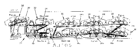
such as for example stinger trailer 10, and a head ramp 12, Trailer 10
includes an upper deck
14 and a lower deck 16. Upper deck 14 has a forward portion 14a pivotally
linked to an over
wheel portion 14b, An upper ramp 14c is pivotally mounted to the rear of over
wheel portion
14b. Upper deck 14 is selectively raised and lowered over lower deck 16 by
means of
stanchions and actuators 18 using for example the lockable actuators
manufactured by Delavan
Industries Inc. of West Seneca, New York, USA. Stanchions and actuators 18 are
pivotally
mounted at their ends so as to extend between upper deck 14 the trailer bed.
When the
actuators are retracted upper deck 14 is lowered until over-wheel portion 14b
rests down onto
wheel well portion 16b of lower deck 16. This positions forward portion 14a
substantially
parallel to, and directly over, forward portion 16a of lower deck 16, and
positions ramp 14c
directly over lower ramp 16c. Forward portion 16a includes one or more
floating belly
portions, meaning deck portions that independently may be raised, lowered or
inclined or
maintained horizontal, for example so as to lower the forward end of forward
portion 16a as
seen in Figure 4. When carrying automobiles this allows forward portion 14a to
also be
lowered, for example, into a position downwardly inclined so as to be
substantially or
somewhat parallel to the inclination of forward portion 16a thereby lowering
the trailer center
of gravity of the trailer load when hauling loads such as automobiles 32,
Lower ramp 160 is
pivotally mounted to wheel well portion 16b and may be inclined downwardly by
lowering the
rear most end of ramp 16c to thereagain lower the center of gravity and to
provide a loading
7
CA 02799853 2015-01-15
ramp. Upper ramp 14c may be also be inclined downwardly to assist in loading
and also to
lower the center of gravity of a load such as a vehicle being carried on upper
ramp 14c.
An over-cab ramp 20 having a safety railing 20a is mounted directly over truck
22 and in particular over truck cab 22a. Actuators and stanchions 18 mounted
under over-cab
ramp 20 allow ramp 20 to be inclined by raising of its rear end. Head ramp 12
is mounted
behind cab 22a and includes an upper deck 24 and a lower deck 26. Upper deck
24 may be
raised directly over lower deck 26 by means of a vertical actuator 28 mounted
vertically,
directly behind truck cab 22a, and by means of stanchions and actuators 18
pivotally mounted
at their upper and lower ends so as to extend diagonally between respectively
upper deck 24,
when raised and lower deck 26. Actuation of the actuators results in raising
and lowering upper
deck 24 in direction C and also provides for inclining of upper deck 24 as
seen in Figure 8.
Bridges 31 are mounted to the forward ends of upper or lower decks 14 and 16
or to the rear-
most ends of upper or lower decks 24 and 26, or some combination thereof so
that when the
lower decks 16, 26 are horizontally aligned or when the upper decks 14, 24 are
horizontally
aligned, loads such as vehicles may travel or be transported across the
bridges from one upper
deck to another, and from one lower deck to another. A head ramp lower deck
extension 26a
may be stored in an upwardly inclined position, or may be lowered when loading
the lowered
deck 26 and to help carry longer loads on the head ramp.
By the various positioning of over-cab ramp 20, head ramp upper deck 24, and
trailer upper deck 14 various combinations of loads may be accommodated as
will be
appreciated by one skilled in the art reviewing the combination of loads
illustrated by way of
example in the accompanying Figures and as described herein.
Thus, with the decks oriented as shown in Figure 4 the number of vehicles that
may be carried at one time is optimized and the center of gravity of the load
and trailer lowered
as much as possible. When loading vehicles such as automobiles 32 or tractors
36, the upper
8
CA 02799853 2015-01-15
decks are lowered and the vehicles are driven onto the upper decks. The upper
decks are then
elevated to their full height. This aligns forward portion 14a with head ramp
upper deck 24
when in its fully elevated position, that is, when upper deck 24 is elevated
so as to be co-planar
with over-cab ramp 20.
The forward-most vehicle on forward portion 14a is then driven onto upper deck
24 and from there onto over-cab ramp 20. Another vehicle may then be driven
from forward
portion 14a onto upper deck 24. With over-cab ramp 20 then inclined so as to
elevate the end
of the vehicle being carried on over-cab ramp 20 adjacent upper deck 24, the
vehicle next
driven onto upper deck 24 may be positioned with its bumper underneath the
elevated end of
the vehicle being carried on over-cab ramp 20. Upper deck 14 is then lowered
to take on two
more vehicles, ramp 14c being lowered to accommodate loading of the vehicles.
Ramp 14c is
then raised to the horizontal once the last vehicle has been loaded onto upper
deck 14.
Upper deck 14 may then be again elevated to its full elevation and the loading
of
vehicles onto lower deck 16 and lower deck 26 may commence. Vehicles are then
driven onto
the lower decks. Once the vehicles are secured on the lower decks the upper
decks are lowered
into positions snugly over the vehicles on the lower decks. The forward
portions 14a and 16a
may be inclined downwardly. Ramp 16c is elevated from contact with the ground.
Keeping in mind the height restrictions restricting the overall height of the
truck
cab and load on over-cab ramp 20, instead of carrying vehicles a pallet load
34 may be placed
on over-cab ramp 20 using a forklift. Vehicle loads such as for example
tractors 36 or
automobiles 32 may then be loaded onto upper deck 24. Depending on the height
of the vehicle
load, and without exceeding the overall height restrictions, a further load
for example pallet
loads 34 may be simultaneously carried on lower deck 26. Pallet loads 34 may
be loaded on
lower deck 26 by rear and side loading onto deck 26 using a forklift. A 40
foot long container
load (not shown) may also be carried on upper deck 14. Again, pallet loads 34
may be carried
9
CA 02799853 2015-01-15
underneath the container load. Pallet loads 34 carried on both lower deck 26
and lower deck 16
may be quickly side-loaded that is loaded traversely, onto the upper and lower
decks. That is,
with upper deck 14 horizontal and in its lowered position as seen in Figure 2,
pallets 34 may be
easily loaded onto upper deck 14 from alongside the trailer thereby
effectively increasing the
carrying capacity of the trailer in its flat-deck mode. The effect of
increasing the load capacity
means that pallet loads which before would be carried on many more feet of
flat-deck can now
be carried on the 40 feet of flat-deck on upper deck 14, and additionally
further pallets carried
on the lower deck 16 effectively make the trailer equivalent to a much longer
conventional flat
bed trailer.
In a preferred embodiment, the trailer, such as stinger steer convertible
trailer 10,
provides a floating-belly style lower deck as better described below for side
loading by forklifts
while also providing a hybrid flexibility for loading and carrying different
kinds of loads in
various combinations to optimize lowering the center of gravity of the load
and trailer
combination where possible. Combinations may include carrying automobiles and
pallets, or
pallets combined with larger loads including containerized loads, subject and
pallets to highway
height and length restrictions. The various loads may be also mixed between
loads carried on
the head ramp and loads carried on the trailer.
In the embodiment of Figure 4, forward portion 16a of lower deck 16 is shown
as a single pair of ramps extending from the front of the trailer back to the
tandem wheel wells,
in the fully lowered position of Figure 3a, forward portion 16a is flat and
lowered between the
side rails 40 into a position corresponding to that shown in Figure 6. Forward
portion 16a may
be elevated while remaining horizontal from its fully lowered position, to its
fully raised
position such as seen in Figure 3 where forward portion 16a is elevated above
the upper edges
of side rails 40. This allows pallets 34 to be side loaded, that is, loaded
laterally in direction A
or sideways relative to the trailer directly onto the wheel-engaging members
16e of forward
portion 16a or onto planking 46 in the further embodiment described below and
shown in
CA 02799853 2015-01-15
figures 12 onward. Where it is desired to carry a load of vehicles on lower
deck 16, as seen in
Figure 4, forward portion 16a may have its forward end lowered and its rear
end elevated to the
level of wheel well portion 16b which extends over the tandem wheel wells 10a.
In the embodiment of Figures 6 and 7, forward portion 16a of lower deck 16
includes a floating belly front ramp 42a and a floating belly rear ramp 42b.
The forward edge
of floating belly rear ramp 42b is adjacent to the rear end of floating belly
front ramp 42a. The
rear end of floating belly rear ramp 42b is adjacent the forward end of wheel
well portion 16b
and wheel wells 10a. The forward end of floating belly front ramp 42a is
adjacent the front
ends of side rails 40. Actuators and Stanchions18 are provided under floating
belly front and
rear ramps 42a and 42b so that floating belly front and rear ramps 42a and 42b
may be
independently raised and lowered relative to side rails 40 while remaining
horizontal or
inclined, and may be independently inclined relative to one another.
This embodiment allows for further flexibility in the hybrid approach
according
to the present invention in carrying mixed loads of for example vehicles,
pallets, and containers
of various sizes. Thus for example, it may be desirable to transport
palletized goods or pallets
34 in a horizontal position. In order to maximize the number of pallets that
may be carried,
floating belly front end rear ramps 42a and 42b are side loaded in direction A
while in their
fully elevated positions such as seen in Figure 3 and, once loaded, lowered
while remaining
horizontal into the fully lowered and horizontal position as seen in Figure
3a. Once the pallets
on the lower deck have been lowered fully into the belly of the trailer, the
upper deck 14
containing its load of a container or containers or pallets or vehicles is
then lowered down so as
to be snugly over the load of pallets on the lower deck. Depending on the
vertical height of the
load carried on upper deck 14, and given the overall height restriction
governing the
transportation of freight or automobiles as the case may be on regulated
roadways, and
depending on the height of the palletized loads it may be that a further
pallet may be carried on
wheel well portion 16b such as seen in Figure 3, or, in order to allow the
upper deck 14 to be
11
CA 02799853 2015-01-15
lowered as much as possible as seen in Figure 3a, no pallet may be carried on
wheel well
portion 16b.
Where instead of carrying pallets on lower deck 16, vehicles are to be loaded,
then the floating belly front and rear ramps 42a and 42b may be inclined so as
to emulate for
example the inclined forward portion 14a as seen in Figure 4 to enable an
automobile to be
carried on wheel well portion 16b with the front wheels of the automobile on
forward portion
16a. As would be known to one skilled in the art of carrying automobiles,
because the
clearance under the automobiles is very limited the angles of inclination that
may be
accommodated by a vehicle being parked partially on a horizontal ramp and
partially on an
inclined ramp is very restricted. Thus the inclined ramps have to be
relatively gently inclined,
depending on. the type of vehicle being carried.
As seen in Figures 3a and 3b, lower ramp 160 is also fully articulated like
floating belly rear ramp 42b. That is, lower ramp 16c is mounted on
stanchions/actuators 18 so
that it may be elevated to be horizontal and substantially co-planar with
wheel well portion 16b,
and may be inclined rearwardly from that position to load and carrying
vehicles such as
automobiles 32 as seen in Figure 4, and may be fully lowered so as to be
horizontal and
substantially co-planar with forward portion 16a of lower deck 16 when in its
fully lowered
position in the belly of the trailer. Thus the articulation of ramp 16c allows
carrying
horizontally thereon loads such as pallets 34 while maximizing the height of
the load that may
be carried under the upper deck and in particular under upper ramp 14c.
In Figure 3, pallets 34 have been loaded onto upper deck 14 while the upper
deck was fully lowered such as in Figure 2 loading may be done by forklifts or
the like side
loading in direction A. Upper deck 14 may then be elevated to provide access
to lower deck
16. Lower deck 16 has been elevated above side rails 40, for example so as to
be at the same
elevation as the upper surface of wheel well portion 16b. Pallets 34 have been
side loaded in
12
CA 02799853 2015-01-15
direction A onto lower deck 16 such as seen in Figure 3, and in particular
onto the floating belly
front and rear ramps 42a and 42b of the forward portion 14a. Pallets 34 so
loaded on to upper
and lower decks 14 and 16 are lowered to, firstly, settle the lower deck down
into the belly of
the trailer, and, secondly, to snug the upper deck down onto the lower deck
load as much as
possible to lower the center of gravity of the upper deck load. Thus, in
Figure 3a no pallet or
pallets are carried on wheel well portion 16b so that upper deck 14 may be
lowered as much as
possible while still allowing carrying of a substantial number of pallets on
lower deck 16.
As seen most clearly in Figures 12 ¨ 14, floating belly front and rear ramps
42a
and 42b are carried on, and actuated independently on their associated
actuators and stanchions
18. Thus floating belly front ramp 42a and floating belly rear ramp 42b may be
independently
raised, lowered, and inclined relative to each other. When for example
floating belly front
ramp 42a is fully lowered down into the belly of the trailer, that is, between
side rails 40 to the
lower-most extremity between the side rails as permitted by the stanchions and
actuators 18, if
a particular load requires that floating belly rear ramp 42b be inclined so as
to provide a ramp
between front ramp 42a and wheel well portion 16b, rear ramp 42b may be
inclined and
lengthened telescopically as for example best seen in Figures 14 and 14a by
the sliding of ramp
section 44a out from underneath ramp section 44b in direction B. Thus floating
belly rear ramp
42b may be shortened or lengthened so as to translate the front end of ramp
section 44a
forwardly or rearwardly to remain consistently adjacent to the rear end of
floating belly front
ramp 42a. Thus, when horizontal, floating belly rear ramp 42b will have the
shortest combined
length between ramp sections 44a and 44b, as for example seen in Figures 12,
12a and 12b.
When inclined however such as seen for example in Figure 4, ramp sections 44a
and 44b will
be telescopically translated relative to one another to lengthen rear ramp 42b
so as to nearly
abut the front end of ramp section 44a against the rear end of floating belly
front ramp 42a.
The continuously adjustable length of floating belly rear ramp 42b
accommodates the various
inclinations that may be desirable for the front and rear ramps 42a and 42b
depending on the
load being carried.
13
CA 02799853 2015-01-15
As also seen in Figures 12, 13 and 14, advantageously planking 46, which is
understood to include not only wood planking but also planking of other
materials or other
removable decking, panels or sections, are removably installed at least in and
along the open
central corridors 14d and 16d in the gap between the pairs of parallel wheel
engaging members
14e and 16e on which vehicles are driven (so that their tires roll along the
ramp members 14e
and 16e). Planking 46 so installed, and preferably removably installed along
the central
corridors 14d, 16d, substantially provide a decking or sheeting over the
larger openings on the
upper and lower decks to assist in the carrying of for example pallets 34. In
particular,
advantageously the upper surfaces 46a of planking 46 are raised at least
slightly above the
corresponding upper surfaces of wheel engaging members 14e and 16e so that
when pallets 34
are deposited during loading down onto the upper and lower decks, the bottom
of the pallets,
which typically are of wood, rest an upper surfaces 46a instead of resting on
the metal of wheel
engaging members 14e, 16e. Planking 46 thus provides increased friction
between the decks
and the undersides of the pallets to inhibit slipping of the loads during
transport.
In the embodiment illustrated, cross members 48 span laterally across and
between the members 14e, 16e so as to support the undersides of planking 46.
The
arrangement of cross members 48 is not intended to be limiting as
longitudinally extending
rigid members may also be employed, whether they are beams or channels or the
like. Further,
in some embodiments of trailers 10, there may be side gaps formed between the
laterally outer
side edges of members 14e, 16e and the corresponding side rails 40, which gaps
may also be
sheeted with planking to cover the side gaps.
Although limited embodiments of stanchions and actuators 18 are illustrated,
it
will be understood to those skilled in the art, that various actuation
assemblies and systems may
be employed to selectively raise, lower, and incline the upper and lower decks
14, 16 and in
particular in the lower deck 16 the forward and rear floating bellies 42a, 42b
without departing
14
CA 02799853 2015-01-15
from the scope of the present invention. It will also be understood by those
skilled in the art
how to provide the hydraulic actuation systems corresponding to the actuators
and stanchions
18 and how to pivotally mount the ends thereof to the side rails or other
trailer structure and to
the upper and lower deck structure so that the upper and lower decks 14, 16
and M particular
the forward and rear floating belly ramps 42a, 42b may be smoothly and stably
actuated and
locked in their desired positions so as to attain the desired orientations of
the upper and lower
decks, and within the lower deck the desired orientations of the floating
belly front and rear
ramps.
As seen in Figures 8 ¨ 11, in a further embodiment of truck 22, the head ramp
upper deck may have a forward and rear portion which may be independently
articulated. Thus
the over-cab ramp 20 may be independently elevated and inclined, independently
of head ramp
upper deck 24. This combined with the ability of over-cab ramp 20 to incline,
the combination
of over-cab ramp 20, and head ramp upper deck 24 may be combined to carry
various loads.
Thus for example, a loading of pallets may be carried as seen in Figure 10
wherein the upper
decks of the head ramp and the over-cab ramp are substantially co-planar and
horizontal. This
provides room on the lower deck of the head ramp to also carry further
pallets. As seen in
Figure 11, over-cab ramp 20 may be inclined to accommodate carrying a vehicle
and allowing a
further vehicle to be carried on the forward and rear ramps of the head ramp
upper deck while
allowing room to carry a further vehicle on the head ramp lower deck.
With the forward and rear ramps of the head ramp upper deck in their fully
lowered position such as seen in Figure 9, loads such as the panel van of
Figure 9a and the
twenty-foot container of Figure 9b may be accommodated on the head ramp while
still allowing
a load to be carried on the over cab ramp.
As will be apparent to those skilled in the art in the light of the foregoing
disclosure, many alterations and modifications are possible in the practice of
this invention
CA 02799853 2015-01-15
without departing from the spirit or scope thereof. Accordingly, the scope of
the invention is to
be construed in accordance with the substance defined by the following claims.
16