Note: Descriptions are shown in the official language in which they were submitted.
CA 02800983 2012-11-28
INDEXING GEAR TRANSMISSION FOR ON-LOAD TAP CHANGERS OF STEP
TRANSFORMERS
The present invention relates to an indexing transmission
for on-load tap changers of tapped transformers with the features
of the independent patent claim.
Indexing transmissions of that kind or similar are
disclosed by, for example, DE 26 08 051 A which shows a
preselector, as well as by US 27 85 242 A, which shows a so-called
turning arrangement. In this known constructional form of indexing
transmissions it is necessary to provide suitable mechanical means
for end position blocking. These end position blocking means have
to reliably prevent the possibility of movement beyond the end
positions of the tap selector or on-load tap changer, which would
normally lead to significant damage of the tap selector.
In addition, DE 10 39 129 A discloses a mechanical end
position block in which a separate blocking disc, which is
coaxially connected with a control disk for actuation of the tap
selector, co-operates with a pawl which in turn can be actuated via
intermediately arranged mechanical means by the control disc. This
end position block is mechanically complicated and, moreover,
unsuitable for blocking two mutually independently movable Maltese
wheels arranged concentrically one above the other.
DE 23 39 973 A shows an arrangement in which an abutment
is disposed on the Maltese cross and which at the appropriate
instant actuates a turning arrangement or preselector by way of a
lever system.
- 1 -
CA 02800983 2012-11-28
DE 40 09 503 C2 discloses a further development of an
indexing transmission for tap selectors of tapped transformers, in
which two Maltese wheels are arranged concentrically one above the
other on a common tap selector axis and are driven by a Maltese
crank having an upper and a lower entrainer pin. These two
entrainer pins are offset relative to one another through 180
degrees and engage in roller slots of the respective Maltese wheel.
In addition, one Maltese wheel co-operates with a turning
abutment, by which a turning lever, which is pivotably arranged on
the shaft, for actuation of a turning means or preselector is
pivoted at a specific point of the switching sequence. Arranged on
the turning lever is a blocking plate which is displaceable by
means of a slot on the shaft carrying the turning lever.
An object of the present invention consists in proposing
an indexing, which operates reliably and with as low friction as
possible and/or with easy running, for an indexing transmission of
an on-load tap changer or tap selector of a tapped transformer, in
which the driven element is reliably fixed in its respective
operational setting.
This object of the invention is achieved by the subject
of the independent patent claim. Features of advantageous
developments of the invention are evident from the dependent
claims. In order to achieve the object of the invention the
present invention proposes an indexing transmission for an on-load
tap changer, tap selector or comparable switch of a tapped
transformer, in which at least one cam disc, which is driven by way
of a spring energy store, co-operates with a drive output disk with
- 2 -
CA 02800983 2012-11-28
engagement elements arranged rotatably mounted thereon. This drive
output disk is connected by the engagement elements rotatably
mounted thereon with a switch shaft to be secure against relative
rotation. This arrangement serves the purpose of allowing the cam
disk in co-operation with the engagement elements of the drive
output disk to trigger a stepped rotation of the switch shaft
through a defined step angle. The present invention provides that
the engagement elements are respectively formed by rollers which
are rotatably mounted at a flat side in the vicinity of the outer
circumference of the disk and which roll on the outer
circumferential surface of the at least one cam disk by a
corresponding engagement profile with convex and concave cam
sections in regular succession and transitioning one into the
other. Such a configuration forms a roller pair in which the
engagement elements constructed as rollers roll on the outer
circumferential surface, which forms an alternatingly curved cam,
of the cam disk without appreciable sliding movements with
accompanying friction effects then occurring. By comparison with a
previously used Maltese transmission the significant advantage
arises of a very easy-running reciprocal drive transmission with at
the same time a very reliable function safe against jamming. The
indexing transmission according to the invention enables blocking
of the disks with the rollers arranged thereon after each indexing
in a desired or definable angular position corresponding with a
defined operational setting. For this purpose, the rollers roll on
suitably profiled blocking cams of the cam disks or cam disc.
- 3 -
CA 02800983 2012-11-28
In the indexing transmission according to the invention
selectably two, three or more engagement elements or rotatable
rollers can be arranged, in respectively, uniform angular pitch at
the outer circumference of the drive output disc. These rotational
axes of the rollers are usefully oriented parallelly to the
rotational axis of the disk and thus also of the switch shaft so
that an easy-running and reliably functioning indexing transmission
with an angular pitch defined in correspondence with the selected
number of rollers and the distribution thereof at the outer
circumference of the disk is formed. The outer profile of the cam
disk and its outer circumferential surface, which is concave at
least in a section, are preferably so designed that during the
indexing the respective roller can roll substantially free of play
in the concave cam section at the circumference of the cam disk
whilst in the blocked position a further movement is reliably
prevented by the intersecting circumferential circles of the drive
output disk and the cam disk and the blocking thereof by two
adjacent rollers.
With the transmission arrangement according to the
invention it is possible to achieve fixing of the disks in the
respectively achieved angular position after each indexing of the
cam disk through a defined rotational angle. The primary objective
of the indexing transmission according to the invention is not the
position-blocking, but the particularly reliable and very
easy-running and low-friction indexing function. Since the known
and previously used friction lock is dispensed with in favor of a
roller lock, a very precisely switching rotary transmission, which
- 4 -
CA 02800983 2012-11-28
operates without appreciable friction, with an indexing function is
made available. The transmission function formed by the indexing
transmission can be influenced within certain constructional limits
by the profiling of the cam disk or the plurality of cam disks
and/or the placing or number of the rollers arranged at the disc.
For example, in the case of a design with six rollers uniformly
distributed at the circumference of the disk drive output angles of
60 or 120 can be realized by means of drive angles of
approximately 80 to 120 depending on the respectively desired
translation ratios. Equally conceivable is influencing of the
characteristics of the transmission function itself for the same
ratio of drive angle to drive output angle, in that, for example, a
polynomial of 5th order or a sloping sinusoidal line of the like is
used. Moreover, it is possible to achieve almost any drive output
angle if no two successive actuations are required in,
respectively, the same direction.
In a further preferred variant of the indexing
transmission a pair of cam disks arranged coaxially or axially
parallel to one another with respectively substantially the same
size and external profile are arranged offset relative to one
another secure against rotation on the shaft coupled with the crank
transmission. This pair of cam disks is disposed in operative
engagement with a corresponding pair of disks, which are arranged
concentrically on the switch shaft and offset relative to one
another, with engagement elements mounted thereon. The disks and
cam disk respectively disposed in operative engagement with one
another are preferably identically constructed and dimensioned in
- 5 -
CA 02800983 2012-11-28
paired manner and respectively arranged offset relative to one
another on the associated shafts thereof in such a manner that a
constrained guidance of the rollers and outer profiles of the cam
disks rolling together is provided. The disk with the rollers
mounted thereon can be further rotated only if the matching concave
cam section is rotated into a position at the respective cam disk
in order to accept a roller. The flowing transitions from the
larger diameter of the cam disk to the concave receiving profile,
which is formed as a recess with smaller diameter and which is
preferably matched by the inner profile thereof and by the inner
radius thereof to the diameter and profile of the corresponding
rollers, then enables, on corresponding rotation of the cam disc,
stepped movement of the drive output disk as well as of the switch
shaft connected therewith to be secure against relative rotation.
In order to enable these desired movements of the shafts arranged
parallel to one another the external profiles of the cam disks
preferably roll substantially free of play or with a small radial
play against the outer circumferential surfaces of the rotatably
mounted rollers or engagement elements of the disk or disks.
As also made clear on the basis of the exemplifying
embodiments described in the following the driving element of the
indexing transmission according to the invention is formed from two
cam disks arranged one above the other. The driven element is
formed from two planes of the disk respectively with six rollers
uniformly distributed at the outer circumference. The cam disks
engage, during the switching over process, in the plane associated
therewith and move the driven element in substantially jolt-free
- 6 -
CA 02800983 2012-11-28
manner from one detent setting or operational setting to the next.
The rollers of the driven element in that case roll low in play on
the respective cam flanks, which are respective sub-sections of a
continuous overall cam formed from a plurality of convex and
concave sections.
An alternative variant of the indexing transmission
according to the invention can provide that the cam disk has at
least one blocking pin, which is arranged at its end face in the
vicinity of its outer circumference and which co-operates with a
star wheel with a plurality of circumferential cam sections, the
start wheel being connected with the switch shaft to be secure
against relative rotation and arranged concentrically with respect
to the disk with the engagement elements. In this variant of the
indexing transmission only one set of disk and cam disk disposed in
operative engagement with one another is required, since the
above-explained second disc, which co-operates with a second cam
disc, is replaced by the pins which are arranged at the cam disk
and which can engage in the star wheel connected with the switch
shaft to be secure against relative rotation. The pitch of this
star wheel, which has relatively deep engagement pockets for
receiving the pin or the plurality of pins, is advantageously
matched to the number of engagement elements or rollers present.
Thus, for example, when three rollers are present also three
engagement pockets at the star wheel are required so that this can
fulfil the desired function. The mentioned star wheel in its
profile vaguely resembles the Maltese disks known from the prior
art, but by comparison with these fulfils a changed task, since it
- 7 -
CA 02800983 2012-11-28
is merely supporting with respect to positioning of the disk
relative to the rotating cam disk in order to be able to position
the disk precisely in the desired angular steps and further rotate
it. For this purpose the cam disk can have a respective blocking
pin on either side adjacent to a circumferential concave cam
section, wherein this concave cam section co-operates with one of
the engagement elements or rotatable pins of the disk and the two
blocking pins co-operate with the concave cam sections of the star
wheel.
The desired switching steps are realized by means of the
indexing transmission according to the invention in that the cam
disk in non-blocked, rotating state rolls by its outer
circumferential surface substantially free of play simultaneously
against two engagement elements or rotatable pins of the disc. A
useful variant of the indexing transmission can, for example, be so
constructed that the concave cam sections of the cam disk and the
corresponding engagement elements or rotatable pins of the disk
connected with the switch shaft to be secure against relative
rotation each have a 1200 pitch. Three rollers arranged uniformly
at the circumference of the disk and optionally concave cam
sections for the blocking pins are required for such a variant.
However, other pitch steps are selectably also possible, in which
two, four or, for example, five or more rollers are arranged in
uniform distribution over the circumference of the disc.
The invention is explained in more detail in the
following by way of embodiments with use of the drawing described
in the following, in which:
- 8 -
CA 02800983 2012-11-28
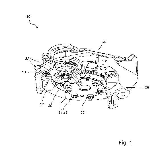
FIG. 1 shows a perspective view of one variant of
embodiment of an indexing transmission according to the invention,
FIG. 2 shows a plan view of the indexing transmission
according to FIG. 1,
FIG. 3 shows a side view of the indexing transmission
according to FIG. 1,
FIG. 4 shows a further perspective view of the indexing
transmission according to FIG. 1,
FIG. 5 shows a schematic plan view of an alternative
variant of embodiment of an indexing transmission according to the
invention,
FIG. 6 shows a perspective view of the indexing
transmission according to FIG. 5 and
FIG. 7 shows a further perspective view of the indexing
transmission according to FIG. 5.
The embodiments described in the following are not to be
understood as restrictive with respect to the indexing transmission
according to the invention, but serve for explanation of the
function and the switching possibilities of the indexing
transmission.
The illustrations of Figures 1 to 4 show in several views
a first variant of embodiment of an indexing transmission according
to the invention, which is denoted generally by the reference
numeral 10. Such an indexing transmission 10 is used particularly
in on-load tap changers (not illustrated) of a tapped transformer
(here similarly not illustrated) in order to thereby activate
and/or switch over tap switches, which are known per se, with
- 9 -
CA 02800983 2012-11-28
mechanical switching elements and/or vacuum switching tubes. The
indexing transmission 10 comprises a crank transmission 12 and at
least one energy store 14, which is coupled therewith and which in
the illustrated embodiment is provided with a helical spring 16
loaded in tension and/or compression. The crank transmission 12 is
coupled by way of a shaft 13 with a pair of cam disks 18 and 20,
which co-operate with and operatively engage a disk 22 with
engagement elements 24 arranged to be rotatably mounted thereon.
These engagement elements 24 are respectively formed as rollers 26
rotatably mounted on the disk 22 in the vicinity of the outer
circumference thereof. The disk 22 together with the engagement
elements 24 or rollers 26 rotatably mounted thereon is connected
with a switch shaft to be secure against relative rotation. Of
this rotationally fast connection, merely one drive output gear
wheel 28 is shown in the illustrated embodiment.
The illustrated transmission arrangement serves the
purpose of allowing the cam disks 18 and 20 in co-operation with
the engagement elements 24 or rollers 26 of the disk 22 to trigger
a stepped rotation of the disk 22 and thus the switch shaft through
a defined step angle, here, for example, 600 in the case of six
rollers 26 present at the outer circumference of the disk 22. The
rollers 26 rotatably mounted on the two flat sides in the vicinity
of the outer circumference of the disk 22 can engage in
corresponding trough-shaped or concave cam sections 30 at the outer
circumferential surface of the respective cam disk 18 or 20. In
this roll pairing the rollers 26 roll on the outer circumferential
- 10 -
CA 02800983 2012-11-28
surface of the cam disks 18 and 20, in which case very low friction
arises.
In the case of the illustrated indexing transmission 10,
in total six rotatable rollers 26 or engagement elements 24 are
arranged at a regular angular pitch at the outer circumference of
the disk 22. The axes of rotation of the rollers 26 are oriented
parallelly to the axis of rotation of the disk 22 and thus also of
the switch shaft so that an easy-running and reliably functioning
indexing transmission 10 with an angular pitch of respectively 60
degrees defined in correspondence with the selected number of
rollers 26 and the distribution thereof at the outer circumference
of the disk 22 is formed. The outer profile of the cam disks 18
and 20 with the respective at least one concave cam section or
segment 30 formed therein is so designed that during the switching
step the rollers 26 can roll substantially free of play in the
concave cam section 30 at the circumference of the respective cam
disk 18 or 20, whilst in the blocked position or in the detent
setting a further movement can be prevented by the intersecting
circumferential circles of the disk 22 and cam disk 18 or 20 and
the blocking thereof by two adjacent rollers 26. The disk 22 with
the rollers 26 mounted thereon can be further rotated only when the
matching recess pocket 30 at the respective cam disk 18 or 20 is
rotated into a position in order to receive a roller 26. The
flowing transitions from the larger diameter of the cam disk 18 or
20 to the concave cam section 30 formed as a recess with smaller
diameter as well as to the web 32 of greater diameter adjoining
thereat, wherein the concave cam section 30 and the transition to
- 11 -
CA 02800983 2012-11-28
the web 32 are matched by the profiles thereof to the diameter and
the profile of the corresponding rollers 26, then enable, with
corresponding rotation of the cam disk 18 or 20, stepped movement
of the disk 22 as well as of the switch shaft coupled therewith.
In order to enable these desired movements of the shafts arranged
parallelly to one another the outer profiles of the cam disks 18
and 20 can roll substantially free of play or with small radial
play against the outer circumferential surfaces of the rotatably
mounted rollers 26 or engagement elements 24 of the disk 22.
The illustrations of Figures 5 to 7 show several views of
an alternative variant of embodiment of the indexing transmission
according to the invention. In this variant of the indexing
transmission 10 the cam disk 18 has two blocking pins 34 which are
arranged at the end face thereof in the vicinity of the outer
circumference thereof and which co-operate with a star wheel 36
with a plurality of circumferential concave cam sections or cam
segments 38. The star wheel 36 itself is connected with the switch
shaft 40 to be secure against relative rotation and in the
illustrated embodiment at the same time forms the disk 22 with the
engagement elements 24 or rollers 26 arranged thereat. In this
variant of the indexing transmission 10 only one set of disk 22 or
star wheel 36 and cam disk 18, which are disposed in operative
engagement with one another, is required, since the above-explained
disk with rollers 26 - which are arranged at both sides and which
co-operate with a pair of cam disks - is redundant by virtue of the
pins 34 arranged at the cam disk 18. The pins 34 can respectively
engage in the concave cam sections 38 arranged on both sides near
- 12 -
CA 02800983 2012-11-28
each roller 26. The pitch of this star wheel 36, which has concave
segments 38 formed to be relative deep for reception of the pins
34, is advantageously matched to the number of engagement elements
24 or rollers 26 present. Thus, for example, in the case of the
three rollers 26 which are present also three pairs of concave cam
sections 38 are required at the star wheel 36 so that this can
fulfil the desired function.
The cam disk 18 has between the two adjacent blocking
pins 34 a concave cam section 42 which co-operates with the
engagement elements 24 or rotatable rollers 26 of the disk 22 or
star wheel 36, wherein in the case of appropriate positioning of
the cam disk 18 and the star wheel 36 the two blocking pins 34
simultaneously co-operate with and engage the concave cam sections
38 of the star wheel 36. The desired switching steps are realized
in that the cam disk 18 in the non-blocked, rotating state in
correspondence with FIG. 5 rolls by its outer circumferential
surface substantially free of play simultaneously against two
rotatable pins 26 of the disk 22 or the star wheel 36. The concave
cam sections and the corresponding rotatable rollers 26 of the star
wheel 36 connected with the switch shaft 40 to be secure against
relative rotation respectively have a 120 pitch. This variant
accordingly has three rollers 26 uniformly arranged at the
circumference of the star wheel 36 and corresponding cam segments
38 for receipt of the blocking pins 34. However, other pitch steps
are selectably also possible, in which two, four or, for example
five or more rollers are arranged in uniform distribution over the
circumference of the disc.
- 13 -