Note: Descriptions are shown in the official language in which they were submitted.
CA 02801028 2012-11-28
WO 2011/153164 PCT/US2011/038606
1
ELECTROPORATION ELECTRODE CONFIGURATION AND METHODS
CROSS REFERENCE TO RELATED APPLICATIONS
[0001] This application claims the benefit of priority under 35 U.S.C.
119(e) to U.S. Provisional
Application Nos. 61/351,235, filed June 3, 2010; and 61/470,975, filed April
1, 2011; the disclosures
of which are herein incorporated by reference in their entirety.
BACKGROUND OF THE INVENTION
[0002] Electroporation is the permeabilization of the cell membrane lipid
bilayer due to an electric
field. Although the physical mechanism that causes electroporation is not
fully understood, it is
believed that electroporation inducing electric fields significantly increase
the potential difference at
the cell membrane, resulting in the formation of transient or permanent pores.
The extent of pore
formation primarily depends on the strength and duration of the pulsed
electric field, causing
membrane permeabilization to be reversible or irreversible, as a function of
the strength and
temporal parameters of the electroporation inducing electric fields.
Reversible electroporation is
commonly used to transfer macro-molecules such as proteins, DNA, and drugs
into cells, while the
destructive nature of irreversible electroporation makes it suitable for
pasteurization or sterilization.
[0003] Typical electric fields strength required for reversible
electroporation range from about 100
V/cm to 450 V/cm. In irreversible electroporation the required electric fields
can range from 200
V/cm to as high as 60,000 V/cm.
[0004] Typical electroporation devices have electrodes (E) that roughly face
one another, as shown
in FIG. 1. In typical electroporation procedures, the targeted cells are
placed between the electrodes
and pulsed voltages or currents, or alternating voltages or currents, are
applied on the electrodes in
order to induce the required electroporation electric field in the volume
between the electrodes. The
relevant electroporation electric field that is produced is roughly
proportional to the potential
difference between the electroporation electrodes and inversely proportional
to the distance (d)
between electrodes (E). In such typical electroporation electrode
configurations, the distance
between the electrodes is constrained by the order of magnitude of the size of
the cells to be
electroporated or by the size of the volume to be electroporated. When high
fields are required, such
as in irreversible electroporation, the conventional design principles lead to
the need for high
potential differences across the electroporation electrodes. Large potential
differences between
electrodes have drawbacks. These include the need for power supplies that are
able to produce these
large potential differences and deliver them in a precise mode. These devices
can be expensive to
fabricate and energy wasteful. Furthermore, the potential differences required
for large electric fields
CA 02801028 2012-11-28
WO 2011/153164 PCT/US2011/038606
-2-
are often large enough to cause water electrolysis, resulting in electrode
depletion and bubble
formation, or electric discharges all of which adversely affect the
electroporation process.
[0005] It would be desirable to develop an electrode configuration that can
deliver high electric
fields with low potential differences between electrodes.
BRIEF SUMMARY OF THE INVENTION
[0006] Presented herein is a new electrode design principle that can achieve
high electric fields with
low potential differences between the electrodes. The central idea is that
high fields are produced at
points of singularity. Therefore, electrode configurations that produce points
of singularity can
generate high fields with low potential differences between the electrodes.
[0007] Provided herein are the concept that "singularity-based configuration"
electrodes design and
method can produce in an ionic substance local high electric fields with low
potential differences
between electrodes. The singularity-based configuration described here
includes: an anode
electrode; a cathode electrode; and an insulator disposed between the anode
electrode and the
cathode electrode. The singularity-based electrode design concept refers to
electrodes in which the
anode and cathode are adjacent to each other, placed essentially co-planar and
are separated by an
insulator. The essentially co-planar anode/insulator/cathode configuration
bound one surface of the
volume of interest and produce desired electric fields locally, i.e., in the
vicinity of the interface
between the anode and cathode. In an ideal configuration, the interface
dimension between the anode
and the cathode tends to zero and becomes a point of singularity.
[0008] An example of one possible method to use the singularity-based
electrode configuration
include a device for electroporation: (1) providing a channel including a
series of co-planar anode
electrodes and cathode electrodes, wherein adjacent anode electrodes and
cathode electrodes are
separated by an insulator; (2) flowing an electrolyte through the micro-
electroporation channel; (3)
flowing a cell through the micro-electroporation channel; and (4) applying a
potential difference
between adjacent anode electrodes and cathode electrodes. Other
electroporation configurations
using the singularity-based electrode configuration are possible. Other
applications to localized high
fields with singularity-based electrodes are also possible
BRIEF DESCRIPTION OF THE FIGURES
[0009] The accompanying drawings, which are incorporated herein, form part of
the specification.
Together with this written description, the drawings further serve to explain
the principles of, and to
CA 02801028 2012-11-28
WO 2011/153164 PCT/US2011/038606
-3-
enable a person skilled in the relevant art(s), to make and use the systems
and methods presented. In
the drawings, like reference numbers indicate identical or functionally
similar elements.
[0010] FIG 1 is a schematic diagram of a typical electroporation electrode
configuration.
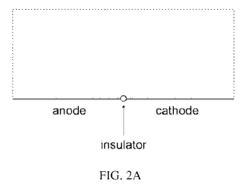
[0011] FIG. 2A is a schematic illustration of electric field streamlines in a
micro-electroporation
configuration, having adjacent electrodes separated by a small insulator.
[0012] FIG. 2B is a schematic illustration of an electrode configuration, in
accordance with one
embodiment presented herein.
[0013] FIG 3 is a schematic illustration of the preparation of an electrode
configuration, in
accordance with one embodiment presented herein.
[0014] FIG. 4(a) is a schematic of the micro-electroporation channel
configuration.
[0015] FIG. 4(b) illustrates a model domain in the absence of a cell.
[0016] FIG. 4(c) illustrates a model domain in the presence of a cell.
[0017] FIG. 5 shows radially-varying electric fields generated in the micro-
electroporation channel.
[0018] FIG. 6 shows how larger electric field magnitudes are present in micro-
electroporation
channels with smaller heights.
[0019] FIG. 7 shows large dimensionless electric field contours are more
focused and span the entire
height of the micro-electroporation channel for small values of A.
[0020] FIG. 8 shows how, in the presence of a cell, dimensionless electric
field contours are
compacted due to the insulating cell membrane.
[0021] FIG. 9 illustrates how cells experience exponentially greater
dimensionless electric field
magnitudes as cell radius increases.
[0022] FIG. 10 shows a temperature distribution in model domain.
[0023] FIG. 11 shows flowing electrolyte velocity arrows in model domain.
[0024] FIG. 12 shows Enterotoxigenic Escherichia coli (ETEC, a type of E.
coli) cells flowing
through a 0.6 m high micro-electroporation channel with a 0.1 V potential
between the electrodes.
[0025] FIG. 13 shows yeast cells flowing through a 4.2 m high micro-
electroporation channel with
a 0.1 V potential between the electrodes.
[0026] FIG. 14 shows the electric field as a function of height (Y) from the
surface at the centerline
of the insulating length for decreasing dimensionless insulator lengths.
[0027] FIG. 15 shows the electric field developed across an E. Coli bacteria
as it flows past an
insulator of 100 nanometers in a channel.
[0028] FIG. 16 shows the electric field developed across a yeast cell as it
flows past an insulator of
100 nanometers in a channel.
CA 02801028 2012-11-28
WO 2011/153164 PCT/US2011/038606
-4-
[0029] FIG. 17 is a table showing secondary current distribution model
paramenters.
[0030] FIG. 18 shows non-dimensional electric field (NDE) magnitudes at X =
0.5, Y = 1 for various
relative insulator thincknesses (I) and domain aspect ratios (A).
[0031] FIG. 19 shows electric field magnitudes along a centerline directly
above the insulator in the
secondary current distribution model.
[0032] FIG. 20 shows how power input to the singularity-induced micro-
electroporation
configuration depends on applied voltage and water conductivity.
[0033] FIG. 21 shows a galvanic electroporation device
[0034] FIG. 22 shows a schematic of the secondary current distribution model
domain.
[0035] FIG. 23 shows an electric field magnitude along the y-centerline.
[0036] FIG. 24 shows power density as a function of load voltage.
DETAILED DESCRIPTION OF THE INVENTION
[0037] Presented herein is a singularity-based electrode configuration, which
enables the generation
of a local high-strength electric field in an electrolyte. The point of
singularity in the context of this
invention is a point in which there is a discontinuity in the potential
distribution in or around and in
contact with the domain of interest. At the design limit, this discontinuity
has a geometrical
dimension of zero. Comparison between FIG. 1 and FIGs. 2A and 2B illustrates
the difference
between previous electrode design concepts (FIG. 1) and the present concept
(FIGs. 2A and 2B),
respectively. FIG. 1 shows a typical configuration designed to produce an
electric field in a volume
of an electrolyte. In the typical configuration the volume of interest is
confined between the
electrodes. The electric field is directly proportional to the voltage
difference between the electrodes
and inversely proportional to the distance between the electrodes. It is
possible to increase the
electric field in the volume of interest by reducing the distance between the
electrodes and/or by
increasing the potential difference between the electrodes. In principle an
infinite electric field can
be produced by a finite potential difference between the electrodes, at the
limit, when the distance
between the electrodes goes to zero. However, since the volume of interest is
between the electrodes,
there is no utility for a configuration in which the distance between the
electrodes is zero.
[0038] The new design concept shown in FIGs. 2A and 2B suggests that the two
electrodes be
placed essentially on the same plane, bounding a surface of the electrolyte
volume of interest. The
anode and the cathode are separated by an insulating gap. In this
configuration the local electric field
at the interface between the electrolyte and anode/insulator/cathode is also a
function of the
dimension of the insulator and the potential difference between the anode and
cathode. However, in
CA 02801028 2012-11-28
WO 2011/153164 PCT/US2011/038606
-5-
this configuration, the volume of interest is bounded on the outer surface by
the electrodes and not
confined between the electrodes. Therefore in an ideal configuration as the
limit of the insulator
dimension goes to zero, the interface between the electrodes becomes a point
of singularity and in
the electrolyte, infinitesimally final differences of potential between the
electrodes can produce an
infinitely high field at the point of singularity. This configuration
facilitates therefore the generation
of very high electric fields in a volume of interest using small potential
differences. FIG. 2A
demonstrates the utility of this design by showing lines of constant electric
fields emanating from a
point of singularity between two electrodes. FIG. 2A shows that the volume
affected by the
singularity-based electrodes is substantial and predictable, and therefore
this electrode design can be
used to produce high electric fields, with low potential differences in a
volume of interest.
[0039] Advances in micro and nanotechnologies can be used to produce the
singularity-based
configuration. FIG. 3 illustrates such a design. The design is based on an
electrically insulating
surface, such as glass. A conductor, such as gold or platinum, is deposited by
vapor deposition on the
glass surface. The thickness of the deposited layer can range from single
nanometers to micrometers.
Generating a cut in the deposited metal, to the glass surface, produces the
insulating gap between the
electrodes. The electrolyte can be placed on the surface of the structure
facing the two electrodes and
the gap, and the high electric fields are produced in the gap.
[0040] Focused laser beams can be used to produce cuts, with widths of single
microns. Numerous
lithographic techniques are capable of producing sub-100 nm features, and
could be used to create
the insulators in a micro-electroporation channel. Immersion lithography is a
photolithography
enhancement technique that places a liquid with a refractive index greater
than one between the final
lens and wafer. Current immersion lithography tools are capable of creating
feature sizes below 45
nm. Additionally, electron beam lithography, a form of lithography that uses a
traveling beam of
electrons, can create features smaller than 10 nm.
[0041] The design described in FIGs. 2A, 2B and 3 can be used in a variety of
configurations. A
typical configuration is generally composed of an electrolyte placed or
flowing over two adjacent
electrodes separated by a small insulator. As shown in FIG. 2A, application of
a small potential
difference between the adjacent electrodes results in a radially varying
electric field emanating from
the insulator. The electric field can be used to electroporate cells suspended
in the electrolyte.
[0042] There are numerous possible designs that employ the singularity-based
electrode design. For
instance, it would be possible to coat a stirrer blade with such a material to
retain the sterility of the
blade. Or it would be possible to coat the walls of a container with such a
design to maintain the
sterility of the walls by producing electric fields.
CA 02801028 2012-11-28
WO 2011/153164 PCT/US2011/038606
-6-
[0043] While the singularity-based design is for electroporation, the
advantage of having the ability
to produce locally in electrolytic solutions, high electric fields with low
potential differences could
be used in deep brain implants, pacemakers and other medical applications.
[0044] As a more detailed illustration of the various possible applications of
the singularity-based
electrodes, we will describe in greater detail and as an example a
configuration in the form of a
"micro-electroporation" channel. As shown in FIGs. 4(a) and 5, mirroring the
configuration and
placing it in series forms a micro-electroporation channel with multiple
electric fields. Cells flowing
through this channel will experience a pulsed electric field. The magnitude of
this electric field can
be adjusted by altering the height of the channel. Furthermore, adjusting the
electrolyte flow rate
alters the duration of the electric field experienced by cells suspended in
the electrolyte.
[0045] A two-dimensional, steady-state, primary current distribution model was
developed to
understand the effect of micro-electroporation channel geometry and cell size
on the electric field in
the flowing electrolyte. In the absence of cells, decreasing the micro-
electroporation channel height
results in an exponential increase in the electric field magnitude in the
center of the channel.
Additionally, cells experience exponentially greater electric field magnitudes
the closer they are to
the micro-electroporation channel walls.
[0046] The presented micro-electroporation channel differs from traditional
macro and micro-
electroporation devices in several ways. In electroporation devices with
facing electrodes, a cell's
proximity has no bearing on the electric field magnitude it will experience.
Conversely, in the micro-
electroporation channel presented, the electric field magnitude experienced by
a cell is dictated by
the gap between the cell and the channel wall. Because of this, cell size does
not affect the potential
difference required to achieve a desired electric field.
[0047] Another difference between the presented micro-electroporation channel
and traditional
macro and micro-electroporation devices is that less electrical equipment is
required. Traditional
macro and micro-electroporation devices require a pulse generator and power
supply. However, in
the micro-electroporation channel presented, the need for a pulse generator is
eliminated since it
contains a series of adjacent electrodes. Furthermore, since the micro-
electroporation channel
presented only requires a small potential difference, a minimal power source
(such as a battery) is
needed.
[0048] The simplicity of electroporation makes it a powerful technology. The
presented micro-
electroporation channel increases the accessibility of electroporation, making
its use feasible for a
wide range of non-traditional applications.
CA 02801028 2012-11-28
WO 2011/153164 PCT/US2011/038606
-7-
[0049] In one embodiment, there is provided a micro-electroporation channel
configuration. The
channel configuration generally includes an anode electrode; a cathode
electrode; and an insulator
disposed between the anode electrode and the cathode electrode. The anode
electrode, insulator, and
cathode electrode are positioned co-planar along one side of the micro-
electroporation channel. The
configuration may further include an electrolyte flowing through the channel
over the anode
electrode, insulator, and cathode electrode. A flow rate control system may be
provided to alternate
the flow of electrolyte through the channel. In one embodiment, the insulator
separates the anode
electrode from the cathode electrode by less than 200 nm, or by less than 100
nm. In another
embodiment, the insulator separates the anode electrode from the cathode
electrode by about 100 nm.
A battery power source may also be provided, avoiding the use of a pulse
generator.
[0050] In another embodiment, the micro-electroporation channel configuration
includes a second
anode electrode positioned on the opposite side of the channel relative to the
first anode electrode; a
second cathode electrode positioned on the opposite side of the channel
relative to the first cathode
electrode; and a second insulator disposed between the second anode electrode
and the second
cathode electrode. The second anode electrode and the second cathode electrode
are generally co-
planar with respect to one another. As such, the electrode configuration
creates a channel, in which a
cell is passed for electroporation.In yet another embodiment, there is
provided a configuration in
which an ionic substance is bounded on one side by a configuration containing
the singularity-based
electrode configuration, in the form of a flat plate or essentially a flat
plate on which an ionic
substance is placed.
[0051] In another embodiment, there is provided a configuration in which the
ionic substance is
surrounded by the singularity-based electrode configuration in the form of a
channel or container in
which the ionic substance is set or through which it flows. The electric
fields at the point of
singularity can be suitable to produce reversible or irreversible
electroporation electroporation in the
cells in the ionic substances. Reversible electric fields from 50 V/cm to 1000
V/cm, 100V/cm to 450
V/cm, DC or AC. Irreversible electric fields from 50 V/cm to 100,000 V/cm,
from 200 V/cm to 30
kV/cm
[0052] In still another embodiment, there is provided a method of micro-
electroporation. The
method generally includes: (1) providing a micro-electroporation channel
including a series of co-
planar anode electrodes and cathode electrodes, wherein adjacent anode
electrodes and cathode
electrodes are separated by an insulator; (2) flowing an electrolyte through
the micro-electroporation
channel; (3) flowing a cell through the micro-electroporation channel; and (4)
applying a potential
difference between adjacent anode electrodes and cathode electrodes. The
method may further
CA 02801028 2012-11-28
WO 2011/153164 PCT/US2011/038606
-8-
include: (5) alternating the flow rate of the electrolyte through the micro-
electroporation channel;
and (6) coupling the anode electrodes and the cathode electrodes to a battery
power source. Each
insulator may separate the anode electrode from the adjacent cathode electrode
by less than 200 nm,
or by less than 100 nm, or by about 100 nm. Such method may be used for
applications such as
water sterilization or cell transfection.
[0053] In another embodiment, there is provided a micro-electroporation
channel configuration,
comprising: an anode electrode; a cathode electrode; and an insulator disposed
between the anode
electrode and the cathode electrode, wherein the anode electrode, insulator,
and cathode electrode are
positioned co-planar along one side of the micro-electroporation channel. An
electrolyte may then
be provided flowing through the channel over the anode electrode, insulator,
and cathode electrode.
The insulator may separate the anode electrode from the cathode electrode by
between 5 nanometers
and two microns. The micro-electroporation channel configuration may further
comprising a power
source selected from a group consisting of: a pulsed potential, an AC
potential, and an electrolytic
reaction involving the electrodes and an ionic solution. The ionic solution
may be a physiological
solution that contains cells, live tissue, or dead tissue. In one embodiment,
the power source is
couple to the electrodes and configured to deliver an appropriate supply of
current in order to create
an adjustable field. The field may be adjusted to meet the application (e.g.,
reversible
electroporation or irreversible electroporation). In one embodiment, a field
is applied for irreversible
electroporation, without causing thermal damage to the cells of interest.
[0054] Traditional macro and micro-electroporation have deficiencies that are
addressed by the
presented micro-electroporation channel. Due to the large quantities of cells
treated in macro-
electroporation, the extent of cell permeabilization varies throughout the
population. While micro-
electroporation addresses this issue, it typically results in lower
throughput. The focused electric
fields in the presented micro-electroporation channel, which can be modified
with channel geometry,
offer better control over cell permeabilization than macro-electroporation
devices. Additionally, the
flow-through nature of the channel makes it suitable for treating large
quantities of cells.
[0055] Another deficiency addressed by the presented micro-electroporation
channel is the need for
large, electrolysis-inducing potential differences in traditional macro and
micro-electroporation
devices. Most macro and micro-electroporation devices have facing electrodes,
which results in a
uniform electric field that is inversely proportional to their separation
distance. Although the
separation distances in micro-electroporation devices are significantly
smaller than those in typical
electroporation devices, they are limited by cell size. Because of this,
large, electrolysis-inducing
potential differences are required to generate a desired electric field. The
presented micro-
CA 02801028 2012-11-28
WO 2011/153164 PCT/US2011/038606
-9-
electroporation channel contains a series of adjacent electrodes separated by
small insulators.
Application of a small, non-electrolysis-inducing potential difference results
in a series of radially-
varying electric fields that emanate from the small insulators. Because of
this, only a small power
source (such as a battery) is required. Reducing the electrical equipment
required makes
electroporation feasible for a wider range of applications.
Potential applications
[0056] The non-dimensional models show that cells of assorted sizes can
experience various electric
field magnitudes by adjusting the micro-electroporation channel height.
Furthermore, the electrolyte
flow rate can be used to control exposure time. These parameters enable a
great deal of control over
the extent of cell permeabilization without the need for complicated
electrical equipment, making
this concept useful for a number of potential applications including water
sterilization and cell
transfection.
Water sterilization
[0057] Contaminated water can cause numerous diseases including diarrhea,
which accounts for 4%
of all deaths worldwide (2.2 million). Most of these deaths occur among
children under the age of
five and represent approximately 15% of all child deaths under this age in
developing nations. It is
estimated that sanitation and hygiene intervention could reduce diarrheal
infection by one-quarter to
one-third; however, this requires access to sterile water, which can be
scarce, particularly in rural
areas of developing nations.
[0058] Enterotoxigenic Escherichia coli (ETEC, a type of E. coli) is a 2 m
long, 0.5 m diameter,
rod-shaped fecal coliform, and is the leading bacterial cause of diarrhea in
developing nations.
Currently, vaccination is the most effective method of preventing diarrhea
caused by ETEC.
However, vaccines are not available in developing nations where ETEC is
endemic.
[0059] It is possible to destroy ETEC with irreversible electroporation using
the concept presented
herein. The results of a dimensional form of the primary current distribution
model show that ETEC
cells in water flowing through the center of a 0.6 m high micro-
electroporation channel with a 0.1
V potential difference between adjacent electrodes experience electric field
magnitudes between
1000 and 10000 V/cm, inducing irreversible electroporation (FIG. 12). It
should be noted that this is
a conservative estimate, since cells flowing through the center of the channel
will experience
relatively low strength electric fields compared to cells flowing closer to
the electrodes.
CA 02801028 2012-11-28
WO 2011/153164 PCT/US2011/038606
-10-
Cell transfection
[0060] Cell transfection is the process of introducing large molecules,
primarily nucleic acids and
proteins, into cells. These large molecules typically enter cells through
transient pores created in the
cell membrane by chemical and physical methods, such as electroporation.
However, due to the bulk
nature of the process, it is difficult to determine the optimal
electroporation parameters for high
transfection efficiency and minimal cell death. Traditional micro-
electroporation could remedy this
problem; however, traditional micro-electroporation is not appropriate for
treating large quantities of
cells.
[0061] In contrast, the flow-through nature of the micro-electroporation
channel presented herein
makes it ideal for treating many cells while maintaining control of the
electric fields they experience.
Yeast is a 4 m diameter cell widely used in genetic research because it is a
simple cell that serves as
a representative eukaryotic model. A dimensional form of the primary current
distribution model
shows that yeast cells flowing through a 4.2 m high channel with a potential
of 0.1 V between the
electrodes experience reversible electroporation inducing electric field
magnitudes, creating the
transient pores needed for cell transfection (FIG. 13). By stacking multiple
micro-electroporation
channels atop one another, it would be possible to increase throughput while
maintaining consistent
electric fields.
Examples
[0062] The following paragraphs serve as example embodiments of the above-
described systems.
The examples provided are prophetic examples, unless explicitly stated
otherwise.
Example 1
Nomenclature for Example I
0 = electric potential
0, = electric potential at anode
0 c = electric potential at cathode
0 ,jiff = electric potential difference between electrodes
L = active electrode length
H = half of micro-electroporation channel height
r = cell radius
CA 02801028 2012-11-28
WO 2011/153164 PCT/US2011/038606
-11-
0 = non-dimensional electric potential
0a = non-dimensional electric potential at anode
0e = non-dimensional electric potential at cathode
X = non-dimensional x-coordinate
Y= non-dimensional y-coordinate
A = channel aspect ratio
R = relative cell radius
E = non-dimensional electric field
T = temperature
Qgen = volumetric heat generation
k = thermal conductivity
p = density
Cp = specific heat at constant pressure
u = x-velocity
u = electrical conductivity
,u = dynamic viscosity
p = pressure
[0063] FIG. 4(a) is a schematic of the micro-electroporation channel
configuration. FIG. 4(b)
illustrates a model domain in the absence of a cell. FIG. 4(c) illustrates a
model domain in the
presence of a cell. FIG. 5 shows radially-varying electric fields generated in
the micro-
electroporation channel. A two-dimensional, steady-state, primary current
distribution model was
developed to understand the effect of micro-electroporation channel geometry
and cell size on the
electric field in the flowing electrolyte. Primary current distribution models
neglect surface and
concentration losses at the electrode surfaces, only taking into account
electric field effects from
ohmic losses in the electrolyte. Therefore, primary current distribution
models are governed by the
Laplace equation:
v20=0
where 0 is the electric potential. Furthermore, electrode surfaces are assumed
to be at a constant
potential, making the boundary conditions at the adjacent electrode surfaces:
0, =Odiff for f<x _ %2 y=0]
CA 02801028 2012-11-28
WO 2011/153164 PCT/US2011/038606
-12-
0,=0 for ~ILI 2<x<_L y=01
where 0 a and 0, are the potentials at the anode and cathode, respectively, 0
diff is the potential
difference between them, and L is the active electrode length. The remaining
symmetry boundaries
are governed by:
x=0 0<y<_H
0O=0 for x=L 0<y<_H
0<x<_L y=H
where H is half of the height of the micro-electroporation channel. Due to the
insulating properties of
cell membranes, cells flowing through the micro-electroporation channel are
modeled as electrically
insulating boundaries, which are identical to symmetry boundaries.
Non-dimensionalization of the primary current distribution model.
[0064] The primary current distribution model was non-dimensionalized to
analyze the effect of
micro-electroporation channel geometry and cell size on electric fields in the
electrolyte. The
Laplace equation in two-dimensional Cartesian coordinates is:
d 2o
d 20 + =0
[0065] Substituting the non-dimensional variables:
odzf
X=x
Y-1
into the Laplace equation yields a non-dimensional form:
d21 2 d2(j) dX2 + H A2 =0
Defining the non-dimensional geometry parameter (channel aspect ratio):
CA 02801028 2012-11-28
WO 2011/153164 PCT/US2011/038606
-13-
H
A=-
L
the non-dimensional Laplace equation becomes:
O 2 A2 d 2(D
2 0
[0066] Substitution of the non-dimensional variables into the boundary
conditions yields:
(DQ =1 for {O<X<_0.5 Y=0)
(D,=0 for {0.5<X<_1 Y=O}
X=O O<Y<_1
0c=0 for X=1 0<Y<_1
0<X<_1 Y=1
[0067] Finally, for a spherical cell, the non-dimensional cell radius
(relative cell radius) is defined
as:
r
R =-
H
where r is the cell radius.
Solution of the primary current distribution model
[0068] The non-dimensional primary current distribution model is characterized
by the channel
aspect ratio (A) and the relative cell radius (R). A parametric study was
performed by varying these
parameters in a series of models. In each model, the non-dimensional potential
distribution was
solved for using the finite element analysis software COMSOL Multiphysics
3.5a. A non-
dimensional electric field, defined as:
E=0D
was calculated using the non-dimensional potential distribution.
[0069] Cells were initially excluded from the models to validate the finite
element solution and to
better understand how micro-electroporation channel geometry affects the
electric field in the
electrolyte. These models are only characterized by the channel aspect ratio
and have a simplified
geometry. This simple geometry, along with the homogenous nature of the non-
dimensional Laplace
equation and three symmetry boundaries enabled an analytical solution using
the separation of
CA 02801028 2012-11-28
WO 2011/153164 PCT/US2011/038606
-14-
variables method. The analytical solution was used to verify the results of
the finite element solution.
Once the finite element solution was verified, cells were included in the
models.
Preliminary coupled thermal model
[0070] In addition to the primary current distribution model, a preliminary,
two-dimensional, steady-
state coupled thermal model was developed to determine the temperature
distribution in the flowing
electrolyte. Three models compose the coupled model: (1) a convection and
conduction model, (2)
the primary current distribution model, and (3) a Navier-Stokes model.
[0071] The two-dimensional, steady-state heat equation with conduction and
convection in the x-
direction is:
d2T + d 2 T +Qgen PCpu dT 0
dx2 dye k k dx
where T is temperature, k is thermal conductivity, p is density, Cp is the
specific heat at constant
pressure, Qgen is the volumetric heat generation, and u is the fluid velocity
distribution in the x-
direction. The volumetric heat generation term, Qgen, is the result of ohmic
heating in the electrolyte,
and in two-dimensions is governed by:
do+do2
Qgen __ ~dx 1 _
where u is the electrical conductivity of the electrolyte, and the potential
distribution is determined
from the primary current distribution model. Additionally, the fluid velocity
distribution in the x-
direction, u, is determined by applying the Navier-Stokes equations to steady
flow between two
horizontal, infinite parallel plates, resulting in: 1 U = 2u~dx)(y2 -HZ)
where ,u is the dynamic viscosity of the electrolyte, and ap/ax is a constant
pressure gradient.
[0072] The boundary conditions of the conduction and convection model are
constant temperature at
the left domain boundary:
T=293K for {x=0 0<y<-H}
thermal insulation and symmetry at the bottom and centerline of the channel,
respectively:
0<x<-L y=0
- = 0 for
dy 0<x<-L y=H
CA 02801028 2012-11-28
WO 2011/153164 PCT/US2011/038606
- 15-
and continuity at the right domain boundary:
dl
dT =0 for {x=L 0<y<_H)
[0073] The coupled thermal model was solved in COMSOL Multiphysics 3.5a for a
2 m high (H=1
pm) 10 m long channel with a 0.1 V potential difference between the
electrodes and water as the
electrolyte. The velocity profile was entered as an expression into the
convection and conduction
model, which used the primary current distribution model to determine the heat
generation term
throughout the model domain. The parameters used in the model are shown in
Table 1 below.
Table 1
Channel
Potential difference Odiff V 0.1
Half channel height H m 1
Active electrode length L m 10
Pressure gradient 3p/ax Pa/ m 100
Water
Thermal conductivity k W/m-K 0.58
Density p kg/m3 998.20
Specific heat at constant pressure Cp J/kg-K 4181.80
Electrical conductivity a S/m 5.5e-6
Dynamic viscosity ,u Pa-s 8.90e-4
Primary current distribution finite element model verification
[0074] The non-dimensional primary current distribution finite element model
was verified with an
analytical solution. Correlation coefficients between the non-dimensional
potential distributions of
the two solutions were computed in MATLAB (R2007a version 7.4) for values of
channel aspect
ratio (A) between 0.1 and 1. The correlation coefficients were 1 for all
values of channel aspect ratio,
indicating that the finite element and analytical solutions are identical.
Non-dimensional primary current distribution model results without cells
[0075] In the absence of cells, the models are only characterized by the
channel aspect ratio (A). As
the channel aspect ratio decreases, the magnitude of the non-dimensional
electric field increases
exponentially in the center of the micro-electroporation channel. FIG. 6 shows
how larger electric
CA 02801028 2012-11-28
WO 2011/153164 PCT/US2011/038606
-16-
field magnitudes are present in micro-electroporation channels with smaller
heights. Furthermore,
high-magnitude non-dimensional electric field contours are more focused and
span the height of the
channel for small channel aspect ratios. FIG. 7 shows large dimensionless
electric field contours are
more focused and span the entire height of the micro-electroporation channel
for small values of A.
Non-dimensional primary current distribution model results with cells
[0076] The electric field in the electrolyte is also affected by the presence
of cells. Due to the
insulating properties of the cell membrane, electric field contours are
compacted, causing cells to
experience exponentially greater electric field magnitudes as the relative
cell radius increases (R).
FIG. 8 shows how, in the presence of a cell, dimensionless electric field
contours are compacted due
to the insulating cell membrane. FIG. 9 illustrates how cells experience
exponentially greater
dimensionless electric field magnitudes as cell radius increases.
Coupled thermal model results
[0077] The temperature distribution in the electrolyte is shown in FIG. 10. A
maximum temperature
of 293.00000059 K is at the insulator and the convective heat transfer due to
the electrolyte flow is
apparent. Additionally, an arrow plot of the electrolyte flow is shown in FIG.
11. The maximum fluid
velocity (at the center of the micro-electroporation channel) for the 1 kPa
pressure difference is
umax=0Ø562 m/s.
[0078] These results show that adjusting micro-electroporation channel height
is a way to control the
range of electric field magnitudes in the flowing electrolyte without
increasing the potential
difference between the electrodes. Models with cells indicate that the closer
cells are to the channel
walls, the higher electric field magnitudes they will experience.
Additionally, the preliminary
coupled thermal model shows a 0.00000059 K temperature increase in the flowing
electrolyte, which
is insufficient to cause thermal cell damage.
[0079] It should be noted that changing the length of the insulator separating
the adjacent electrodes
would affect the electric field in the electrolyte. More specifically,
electric field magnitudes
throughout the electrolyte would decrease by increasing the length of the
insulator.
Example 2
[0080] The theoretical highest electric field can be produced in the
configuration discussed in this
invention when the dimension of the insulating singularity between the voltage
sources tends to limit
CA 02801028 2012-11-28
WO 2011/153164 PCT/US2011/038606
-17-
of zero. We have used the same methodology of analysis to evaluate what is the
effect of the
insulating gap thickness on the electric field produced. The results show that
a technologically
achievable 100 nanometer gap can produce the desired effects.
[0081] The models were done in a similar way to those described in the
previous example with non-
dimensional insulation lengths varying from 0.01 to 0.1 (insulation
length/domain length) for an
aspect ratio of 0.1. The non-dimensional insulation length can be scaled to
the domain height by
dividing by the aspect ratio. FIG. 14 is a plot that shows the non-dimensional
electric field (EF)
strength at X=0.5, for different insulation thicknesses. In other words, FIG.
14 shows the electric
field as a function of height Y from the surface at the centerline of the
insulating length for
decreasing dimensionless insulator lengths.
[0082] FIG. 15 shows the electric field developed across an E. Coli bacteria
as it flows past an
insulator of 100 nanometers in a channel. FIG. 15 shows specific applications
considering a
practical insulation length for the E. coli and yeast of the previous example.
The results show that
IRE and RE inducing electric fields are still developed with a 100 nm
insulator, respectively. In this
case the active electrode length is 5 m, not that that has an effect on the
results. In summary, for the
E. coli models, H = 0.3 m, L = 5 m, and IL = 100 nm; for the yeast models, H
= 2.1 m, L = 5
m, and IL =100 nm.
[0083] The results for yeast are given in FIG. 16. FIG. 16 shows the electric
field developed across
a yeast cell as it flows past an insulator of 100 nanometers in a channel.
Example 3
[0084] This example is similar to the Example 1 and Example 2. However,
Example 3 introduces a
new concept. Because the voltage difference across the insulator can be very
small, it can be also
produced through electrolysis between two dissimilar metals separated by the
insulator and brought
in electric contact through the electrical conductive media. This
configuration may allow for the
unprecedented miniaturization of single-cell micro-electroporation devices and
micro-batteries.
Furthermore, while each application is independent, by combining them, it is
possible to perform
single-cell micro-electroporation with no power input, through electrolysis.
In the process, it is even
possible to produce electric power.
[0085] Electrochemical cells are devices capable of delivering electrical
energy from chemical
reactions (galvanic cells), or conversely, facilitating chemical reactions
from the input of electrical
energy (electrolytic cells). All electrochemical cells are composed of at
least: (1) two electrodes
where chemical reactions occur, (2) an electrolyte for ion conduction, and (3)
an external conductor
CA 02801028 2012-11-28
WO 2011/153164 PCT/US2011/038606
-18-
for continuity. Oxidation (the loss of electrons) occurs at one electrode (the
anode) and reduction (the
gain of electrons) occurs at the other (the cathode).
[0086] Both the anode and cathode have characteristic potentials that depend
on their respective
chemical reactions. The difference in these characteristic potentials dictates
either the amount of
work that the coupled chemical reactions can perform (galvanic cell), or the
amount of work
necessary to reverse the coupled chemical reactions (electrolytic cell).
Thermodynamically, at
constant temperature and pressure, this is described by the change in Gibb's
free energy:
AG = -nFAOCeii
where n is the stoichiometric number of electrons transferred, F is Faraday's
constant, and AOCell is
the potential difference of the coupled reactions. A negative change in Gibb's
free energy implies
that a chemical reaction is favorable and is able to perform work (galvanic
cell). Conversely, a
positive change in Gibb's free energy implies an unfavorable reaction that
will need work input to
proceed (electrolytic cell).
[0087] Since the Gibb's free energy is a thermodynamic quantity, it is only
useful for describing
systems at equilibrium. In an operating electrochemical cell a passage of
current takes place, which
implies that the system is not at equilibrium. The passage of current causes
potential drops in the
electrochemical cell, resulting in a potential difference that deviates from
that observed at
equilibrium. This deviation is termed overpotential and can be attributed to
three types of losses: (1)
surface, (2) concentration, and (3) ohmic.
[0088] Surface losses occur due to the kinetic limitations at an electrode
surface. These kinetic
limitations are typically governed by mass transfer, electron transfer at the
electrode surface,
chemical reactions preceding or following the electron transfer, and other
surface reactions.
[0089] Concentration losses are caused by mass-transport limitations, which
result in the depletion
of charge-carriers at the electrode surface. This depletion establishes a
concentration gradient
between the electrode surface and bulk electrolyte, causing a potential drop.
[0090] Ohmic losses are primarily associated with ionic current flow in the
electrolyte. This is
governed by Ohm's law:
i= -kVO
where i is the ionic current, k is the electrolyte conductivity, and 0 is the
electric potential.
Therefore, for a given current, electrolyte conductivity largely influences
the ohmic potential drop in
the electrolyte.
CA 02801028 2012-11-28
WO 2011/153164 PCT/US2011/038606
-19-
Powerless single cell micro-electroporation
[0091] Although typical electroporation and micro-electroporation are
procedurally straightforward,
they both require at least a pulse generator and a power supply, which limits
the accessibility of the
technology outside of a laboratory or industrial setting. Elimination of this
electrical equipment
would allow electroporation to address small scale, far-reaching practical
problems, such as
destroying pathogens in contaminated water in developing nations.
[0092] Presented herein is an electrochemical cell configuration for
performing electroporation
without a pulse generator and minimal to no external power input. This
electrochemical cell
configuration is composed of an electrolyte flowing by a series of two
adjacent, dissimilar metal
electrodes separated by small insulators. When this configuration is in a non-
equilibrium state,
radially-varying electric fields emanating from the small insulators are
present in the flowing
electrolyte. These electric fields will electroporate biological cells
suspended in the electrolyte or
growing on the surface.
[0093] The crux of the concept presented is to utilize the ohmic potential
drop in the electrolyte to
perform electroporation. This ohmic potential drop establishes an electric
field in the electrolyte,
which at a given location is defined as the negative gradient of the local
electric potential:
E=-VO
[0094] Therefore, to maximize the electric field in the electrolyte (1) the
electric potential drop in the
electrolyte has to be increased or (2) the electric potential drop needs to
take place over a small
distance. In electrolytic cells it is relatively easy to increase the
potential drop in the electrolyte by
adjusting the energy being input into the system. However, since the ultimate
goal of this concept is
to perform electroporation with no power input, a galvanic cell needs to be
utilized, leaving little
control of the potential drop in the electrolyte. Therefore, to increase the
electric field magnitude in
the electrolyte, the electrochemical cell geometry needs to be altered.
Example 4
[0095] This example demonstrates the feasibility of a singularity-induced
micro-electroporation; an
electroporation configuration aimed at minimizing the potential differences
required to induce
electroporation by separating adjacent electrodes with a nanometer-scale
insulator. In particular, this
example presents a study aimed to understand the effect of (1) insulator
thickness and (2) electrode
kinetics on electric field distributions in the singularity-induced micro-
electroporation configuration.
A non-dimensional primary current distribution model of the micro-
electroporation can still be
performed with insulators thick enough to be made with micro-fabrication
techniques. Furthermore,
CA 02801028 2012-11-28
WO 2011/153164 PCT/US2011/038606
-20-
a secondary current distribution model of the singularity-induced micro-
electroporation
configuration with inner platinum electrodes and water electrolyte indicates
that electrode kinetics do
not inhibit charge transfer to the extent that probatively large potential
differences are required to
perform electroporation. These results indicate that singularity-induced micro-
electroporation could
be used to develop an electroporation system that consumes minimal power,
making it suitable for
remote applications such as the sterilization of water and other liquids.
[00961 The configuration, termed singularity-induced micro-electroporation, is
composed of an
electrolyte atop two adjacent electrodes separated by a small insulator.
Application of a small
potential difference between the adjacent electrodes results in a radially
varying electric field
emanating from the small insulator (FIG. 2A). Since it has been shown that
applying an electric field
along small portions of the cell membrane can induce electroporation, this
radially varying electric
field can be used to electroporate cells suspended in the electrolyte.
[0097] In order to implement the micro-electroporation channel, or other
devices utilizing
singularity-induced micro-electroporation, the practical feasibility of the
configuration needs to be
further analyzed. Understanding the effect of (1) insulator thickness and (2)
electrode kinetics on
electric field distributions in the singularity-induced micro-electroporation
configuration is
particularly important.
[0098] The insulator is the smallest feature in the singularity-induced micro-
electroporation
configuration. Because of this, it is one of the factors limiting the
implementation of devices that
utilize the singularity-induced micro-electroporation configuration. The
effect of insulator thickness
on electric field distribution in the singularity-induced micro-
electroporation configuration needs to
be analyzed to ensure that insulators thick enough to be created with micro-
fabrication techniques
can generate electroporation inducing electric field magnitudes at small
potential differences.
[0099] In order to perform singularity-induced micro-electroporation with only
a minimal power
source (such as a battery), a direct current must be transferred from the
electrodes to the electrolyte
via electrochemical reactions. Because of this, the kinetics of the
electrochemical reactions at the
electrodes can inhibit current transfer. For singularity-induced micro-
electroporation, the primary
implication of inhibited current transfer is that prohibitively large
potential differences could be
required to generate electroporation inducing electric fields magnitudes. In
order to ensure that this is
not the case, the effect of electrode kinetics on electric field magnitudes in
the singularity-induced
micro-electroporation configuration need to be examined.
[00100] In this example we present (1) a modified, non-dimensional, primary
current distribution
model to analyze the effect of insulator thickness on the micro-
electroporation channel, and (2) a
CA 02801028 2012-11-28
WO 2011/153164 PCT/US2011/038606
-21-
secondary current distribution model of the singularity-induced micro-
electroporation configuration
with platinum electrodes and water electrolyte. The primary purpose of these
models is to further
assess the feasibility of singularity-induced micro-electroporation.
Additionally, the secondary
current distribution model is used to investigate the effect of water
conductivity and applied voltage
on the electric field distribution, and power input of the singularity-induced
micro-electroporation
configuration.
Modified, non-dimensional, primary current distribution model for analyzing
the effect of insulator
thickness on the micro-electroporation channel
[00101] Our previously developed, two-dimensional, steady-state, primary
current distribution model
was non-dimensionalized to analyze the effect of insulator thickness on the
electric field in the
electrolyte of the micro-electroporation channel.
[00102] Since this model neglects surface and concentration losses at the
electrode surfaces, it is
governed by the Laplace equation:
where 4c` is the electric potential. Furthermore, electrode surfaces are
assumed to be at a constant
potential, making the boundary conditions at the adjacent electrode surfaces:
AK, ( o
fit? 10 `i
where and are the potentials at the anode and cathode, respectively, s the
potential
difference between the them. The remaining boundaries are insulation/symmetry
boundaries and are
governed by:
Substituting the non-dimensional variables:
into the Laplace equation in two-dimensional Cartesian coordinates yields:
CA 02801028 2012-11-28
WO 2011/153164 PCT/US2011/038606
-22-
itf [00103] In the above relations, L is the active electrode length and H is
half of the height of the micro-
electroporation channel. Defining the non-dimensional geometry parameter
(aspect ratio):
F
t~.
the non-dimensional Laplace equation becomes:
Substitution of the non-dimensional variables into the boundary conditions
yields:
[00104] Finally, the non-dimensional insulator thickness (relative insulator
thickness) is defined as:
L
Model solution.
[00105] The non-dimensional primary current distribution model is
characterized by the aspect ratio
(A) and relative insulator thickness (I). A parametric study was performed by
varying I and A in a
series of models. In each model, the non-dimensional potential distribution
was solved for using a
finite difference method implemented in MATLAB (R2007a version 7.4). A non-
dimensional
electric field defined as:
was calculated using the non-dimensional potential distribution.
Secondary current distribution model of singularity-induced micro-
electroporation
[00106] A two-dimensional, steady-state, secondary current distribution model
was developed to
analyze the effects of electrode kinetics on singularity-induced micro-
electroporation. Like primary
current distribution models, secondary current distribution models account for
electric field effects
CA 02801028 2012-11-28
WO 2011/153164 PCT/US2011/038606
-23-
from ohmic losses in the bulk electrolyte, and are therefore governed by the
Laplace equation (Eqn.
1) in that region. However, unlike primary current distribution models,
secondary current distribution
models account for kinetic losses at the electrode surfaces. Since kinetic
losses strongly depend on
the potential at an electrode surface, the boundary conditions at the adjacent
electrode surfaces are:
. .. ---r~ ~t= ~ fit; , ; ,
where ja and jc are the current densities at the anode and cathode,
respectively, is the
conductivity of the bulk electrolyte, and F''"` and `s;r' are the surface
overpotentials at the anode and
cathode, respectively. Overpotential represents a departure from the
equilibrium potential at an
electrode surface, and is defined as:
where E is the equilibrium potential for an electrochemical reaction at
standard state, typically 293
K at 1 atm.
Electrode kinetics model.
[00107] Neglecting concentration losses, the relationship between current and
potential at electrode
surfaces is commonly described by a modified version of the Butler-Volmer
model:
li.. R I
[00108] Conceptually, the first term describes the anodic (reduction)
contribution to the net current at
a given potential, while the second term describes the cathodic (oxidation)
contribution to the net
current. With that in mind, the variables in the Butler-Volmer model are:
jo, the exchange current density. The exchange current density is the current
density where the anodic
and cathodic contributions are equal, resulting in no net current.
as and ac, the anodic and cathodic transfer coefficients, which respectively
describe the energy
required for each reaction to occur.
rls, the surface overpotential, the deviation of the electrode potential from
its equilibrium potential.
F, the Faraday constant (96500 C/mol).
R, the universal gas constant (8.314 J /mol-K).
CA 02801028 2012-11-28
WO 2011/153164 PCT/US2011/038606
-24-
T, the temperature of the electrode reaction (K ).
[00109] The exchange current density, and the anodic and cathodic transfer
coefficients are
determined experimentally, typically by fitting current-potential data to the
Butler-Volmer model.
However, in some cases, it is more convenient to fit current potential data to
simpler forms (i.e.,
linear).
Development of the current density boundary conditions.
[00110] A voltage must be applied to the cell suspension to generate an
electric field for
electroporation. Because of potential losses due to irreversibilities (E10 ),
the applied voltage (Vappi)
must be greater than the equilibrium potential (Eeq) of the electrochemical
cell [33]:
[', Ixz T
[00111] The equilibrium potential of the electrochemical cell is the
difference between the anode and
cathode reduction equilibrium potentials at standard state (E a and E e,
respectively):
y
[00112] Irreversible losses have three classifications: 1) surface losses from
sluggish electrode
kinetics; 2) concentration losses due to mass-transfer limitations; and 3)
ohmic losses in the
electrolyte.
[00113] Since concentration losses are neglected in secondary current
distribution models, the
irreversible losses can be represented as:
A
where is the ohmic loss in the electrolyte, and can be further decomposed to:
f1ja
[00114] Combining equations results in:
which provides a more detailed relation for the voltage that must be applied
to the electrochemical
cell to compensate for irreversible losses. Since kinetic models provide the
net current density at an
CA 02801028 2012-11-28
WO 2011/153164 PCT/US2011/038606
-25-
electrode surface as a function of surface overpotential, the equation above
can be separated to obtain
the surface overpotentials at the anode and cathode:
[00115] Substituting these relations into the modified version of the Butler-
Volmer equation relates
the surface potentials at the anode and cathode to their respective current
densities, enabling an
implicit numerical solution.
exp-
ex-P
Model parameters.
[00116] The parameters used in the secondary current distribution model are
outlined in the table in
FIG. 17.
[00117] The secondary current distribution model domain is shown in FIG. 4(b).
The domain is 10
microns long, has a 100 nanometer thick insulator, and is 20 microns high.
Since previous results
show that decreasing domain height exponentially increases electric field
magnitudes, the height of
the domain was made sufficiently large to determine the minimum electric field
magnitudes that can
be generated when accounting for electrode kinetics.
[00118] Since we would like to use the singularity-induced micro-
electroporation configuration for
water sterilization, the bulk electrolyte is water. The electrical
conductivity of water typically varies
between 0.0005 and 0.05 S/m.
[00119] The anode and cathode are modeled as inert platinum electrodes. In
water, the
electrochemical reactions that take place at the electrode surfaces are
identical to those in water
electrolysis. At the anode, water is oxidized:
21H .#.1 (a<s)=41- ~ ll 40
CA 02801028 2012-11-28
WO 2011/153164 PCT/US2011/038606
-26-
[00120] Under standard conditions, this reaction has a reduction equilibrium
potential (E a) of 1.23 V
and an exchange current density (ja,o) of 1028 A/m2. Additionally, the
transfer coefficients ((Xa,a and
aa,e) were assumed to be 0.5. At the cathode, water is reduced:
414-,-0 4L
[00121] Under standard conditions, this reaction has a reduction potential (E
, ) of -0.83 V and an
exchange current density (je,o) of 10 A/m2. Similar to the water oxidation
reaction at the anode, the
transfer coefficients ((Xe,a and ae,,) were assumed to be 0.5. Therefore, the
net reaction in the
platinum-water singularity-induced micro-electroporation system is:
[00122] Under standard conditions, this reaction has an equilibrium potential
(Eeq) of 2.06 V that must
be exceeded to generate an electric field distribution in the water.
[00123] It should be noted that since saline is a water based solution, these
electrochemical reactions
are also applicable to a more traditional electroporation system. Therefore,
this secondary current
distribution model could easily be modified to analyze singularity-induced
micro-electroporation in a
saline solution by changing the bulk electrolyte conductivity.
Model solution.
[00124] The secondary current distribution model is affected by the
conductivity of the water
electrolyte(s) and voltage applied (Vappi) to the electrochemical cell. A
parametric study was
performed by varying these parameters in a series of models. In each model,
the potential
distribution was solved for using the finite element analysis software COMSOL
Multiphysics 4.0a.
The electric field defined as:
was calculated using the potential distribution. Furthermore, by integrating
the current density at the
anode or cathode boundary, the total current (jt of ) through the model was
determined. Using the
total current through the model, the power input defined as:
was calculated.
CA 02801028 2012-11-28
WO 2011/153164 PCT/US2011/038606
-27-
Non-dimensional primary current distribution model for analyzing the effect of
insulator thickness
[00125] The results of the non-dimensional primary current distribution model
show that decreasing
the relative insulator thickness (I) increases the magnitude of the non-
dimensional electric field
(NDE) at the center of the micro-electroporation channel (FIG. 18). More
specifically, the extent of
the increase in the nondimensional electric field magnitude due to relative
insulator thickness
depends on the aspect ratio (A). At low aspect ratios, decreasing relative
insulator thickness
substantially increases the non-dimensional electric field. Decreasing the
relative insulator thickness
from 0.9 to 0 (singularity) at an aspect ratio of 0.1 results in a 413%
increase in non-dimensional
electric field magnitude. Conversely, at high aspect ratios, decreasing the
relative insulator thickness
negligibly increases the non-dimensional electric field. At an aspect ratio of
2, decreasing the relative
insulator thickness from 0.9 to 0 results in a 115% increase in non-
dimensional electric field
magnitude.
Secondary current distribution model of singularity-induced micro-
electroporation - Effect of water
conductivity and applied voltage on electric field distribution.
[00126] The conductivity of the water (s) and the applied voltage (Vappl) both
influence the electric
field distribution in the singularity-induced micro-electroporation
configuration. At applied voltages
lower than ,3.2 V, low conductivity water contains substantially larger
electric field magnitudes than
high conductivity water (FIG. 19). For example, at an applied voltage of 2.7
V, the electric field
magnitudes at the center of the insulator are 0.06, 0.38, and 1.64 kV/cm at
water conductivities of
0.05, 0.005, and 0.0005 S/m, respectively. Furthermore, at applied voltages
lower than 2.8 V,
increasing the applied voltage exponentially increases electric field
magnitudes in the water.
Conversely, at applied voltages higher than 2.8 V, the electric field
distribution becomes constant
and independent of water conductivity. At an applied voltage of 3.5 V, the
electric field magnitudes
at the center of the insulator are 26.4, 33.1, and 39.8 kV/cm at water
conductivities of 0.05, 0.005,
and 0.0005 S/m, respectively.
Effect of water conductivity and applied voltage on power input.
[00127] The power input to the singularity-induced micro-electroporation
configuration is also
dependent on the conductivity of the water and the applied voltage (FIG. 20).
At applied voltages
less than -2.6 V, power input is independent of water conductivity and
increases exponentially with
applied voltage. For example, at an applied voltage of 2.4 V, the powers input
to the singularity-
induced micro-electroporation configuration are 1.09, 1.05, and 0.92x10⁻⁵
W/cm2 at water
CA 02801028 2012-11-28
WO 2011/153164 PCT/US2011/038606
-28-
conductivities of 0.05, 0.005, and 0.0005 S/m, respectively. Conversely, at
applied voltages greater
than -2.6 V, the power input becomes constant and is highly dependent on the
water conductivity. A
singularity-induced micro-electroporation configuration with low conductivity
water (0.0005 S/m)
requires the least power input, 0.23 W/cm2 at an applied voltage of 3.5 V.
The power input required
by the singularity-induced micro-electroporation configuration substantially
increases with water
conductivity. Configurations with 0.005 and 0.05 S/m water conductivities
require 1.93 and 16.20
W/cm2, respectively.
Effect of insulator thickness
[00128] The results of the non-dimensional primary current distribution model
demonstrate the
practical feasibility of the micro-electroporation channel. In our previous
work, we predicted that
increasing the insulator thickness would decrease the electric field
magnitudes throughout the
electrolyte of the micro-electroporation channel. While our results
quantitatively support this
prediction, they also indicate that electroporation inducing electric fields
can be generated with
insulators thick enough to be created with micro-fabrication techniques. For
example, applying a
0.5V potential difference in a micro-electroporation channel with an active
electrode length (L) of 10
mm, micro-electroporation channel height (2H) of 2 mm, and insulator thickness
(i) of 100 nm (non-
dimensional data for A=0.1, 1=0.01), can generate electric field magnitudes in
excess of 10 kV/cm,
which are sufficient for inducing irreversible electroporation. Numerous
lithographic techniques are
capable of producing sub-100 nm features, and could be used to create the
insulators in a micro-
electroporation channel. Immersion lithography is a photolithography
enhancement technique that
places a liquid with a refractive index greater than one between the final
lens and wafer. Current
immersion lithography tools are capable of creating feature sizes below 45 nm.
Additionally,
electron beam lithography, a form of lithography that uses a traveling beam of
electrons, can create
features smaller than 10 nm.
Secondary current distribution model of singularity-induced micro-
electroporation
[00129] Electrochemical reactions must transfer a direct current from the
electrodes to the electrolyte
to perform singularity-induced micro-electroporation. The kinetics of
electrochemical reactions can
inhibit current transfer and potentially necessitate prohibitively large
potential differences to generate
electroporation-inducing electric field magnitudes. Therefore, to adequately
analyze the feasibility of
implementing a singularity-induced micro-electroporation system, the effect of
electrode kinetics on
electric field magnitudes must be understood. The secondary current
distribution model of the
CA 02801028 2012-11-28
WO 2011/153164 PCT/US2011/038606
-29-
singularity-induced micro-electroporation configuration with platinum
electrodes and water
electrolyte accounts for electrode kinetics. The results of this model: (1)
demonstrate the practical
feasibility of implementing a singularity-induced micro-electroporation
system, (2) predicts the
upper limit to the electric field magnitudes of the system, and (3) provides
data for optimizing the
power input necessary to obtain a desired electric field distribution.
[00130] The practical feasibility of creating a singularity-induced micro-
electroporation system is
demonstrated by the results of the secondary current distribution model with
platinum electrodes and
water electrolyte. The results show that electric fields in excess of those
required to induce reversible
(1- 3 kV/cm) and irreversible (10 kV/cm) electroporation can be generated in
water with platinum
electrodes. For instance, in water with a conductivity of 0.0005 S/m, an
applied voltage as low as 2.8
V (0.7 V larger than Eeq) can generate electric fields sufficient to induce
reversible electroporation
near the insulator surface. Increasing the applied voltage by 0.1 V generates
electric fields capable of
inducing irreversible electroporation near the insulator surface, and
reversible electroporation at
distances up to -0.7 pm from the insulator. Although lower electric field
magnitudes are present in
higher conductivity water (0.005 or 0.05 S/m), minor increases in applied
voltage result in similar
reversible and irreversible electroporation inducing electric fields.
[00131] The trend shown in FIG. 19 indicates that there is an upper limit to
the electric field
magnitudes that can be generated in the singularity-induced micro-
electroporation system. For this
system, the low exchange current density of the anode electrochemical reaction
(j0,a) limits the
current through the system. As a result, as the applied voltage increases, the
water conductivity has
less of an influence on the electric field distribution. Furthermore, at large
applied voltages,
increasing the applied voltage negligibly changes the electric field
distribution, indicating the upper
limit of the electric field magnitudes that can be generated with this system.
Close to the insulator,
the electric field magnitudes at the upper limit are well above the magnitudes
required to induce
reversible and irreversible electroporation. However, if large electric field
magnitudes are required
away from the insulator, the upper limit may become an important design
consideration.
[00132] The secondary current distribution model of singularity-induced micro-
electroporation can be
used to optimize the power input to the system. As previously noted, at large
applied voltages, water
conductivity is negligibly influential and the electric field distribution
becomes constant with
increasing applied voltage (FIG. 19). FIG. 20 shows that while power input
also becomes constant at
large applied voltages, it is substantially affected by water conductivity. In
general, low conductivity
water (0.0005 S/m) generates the largest electric field magnitudes with the
least power input, and
high conductivity water (0.05 S/m) generates the smallest electric field
magnitudes with the most
CA 02801028 2012-11-28
WO 2011/153164 PCT/US2011/038606
-30-
power input. Therefore, decreasing the water conductivity is the most
effective method for
optimizing the power input to the system.
[00133] It should be noted that the methodology used for developing the
secondary current
distribution model of singularity-induced micro-electroporation could be used
to model a variety of
electroporation devices. With appropriate electrode kinetics parameters,
numerous electrode
materials and electroporation configurations could be examined. These models
would aid in
experimental studies by providing electric field distributions throughout the
electrolyte. Additionally,
they would facilitate the optimal design of electroporation systems for a
variety of applications.
[00134] The singularity-induced micro-electroporation configuration offers
numerous advantages
over traditional macro and micro-electroporation devices. In electroporation
devices with facing
electrodes, a cell's proximity has no bearing on the electric field magnitude
it will experience.
Conversely, in a singularity-induced micro-electroporation configuration, the
electric field
magnitude experienced by a cell is dictated by the gap between the cell and
the surface of the
configuration. Because of this, cell size does not affect the potential
difference required to achieve a
desired electric field.
[00135] Another advantage of the singularity-induced micro-electroporation
configuration over
traditional macro and micro-electroporation devices is that less electrical
equipment is required.
Traditional macro and micro-electroporation devices require a pulse generator
and power supply.
However, by placing singularity-induced micro-electroporation configurations
in series, as is done in
the micro-electroporation channel, the need for a pulse generator is
eliminated. Furthermore, as
validated by the secondary current distribution model, only a small potential
difference is required.
Because of this, only a minimal power source (such as a battery) is needed.
[00136] The practical feasibility of singularity-induced micro-electroporation
systems were assessed
by examining the effect of insulator thickness and electrode kinetics on
generated electric field
distributions. Two models were developed to understand these effects: (1) a
modified, non-
dimensional, primary current distribution model of a micro-electroporation
channel, and (2) a
secondary current distribution model of the singularity-induced micro-
electroporation configuration
with platinum electrodes and water electrolyte.
[00137] A previously developed, non-dimensional, primary current distribution
model was modified
to analyze the effect of insulator thickness on the electric field
distribution of a micro-electroporation
channel. Increasing the insulator thickness exponentially reduces the electric
field magnitude directly
above the center of the insulator and inhibits the permeation of high-strength
electric fields in the
electrolyte. However, high-strength electric fields can still be generated
with insulators thick enough
CA 02801028 2012-11-28
WO 2011/153164 PCT/US2011/038606
-31 -
to be created with MEMS manufacturing techniques. Therefore, insulator
thickness does not inhibit
the practical feasibility of creating singularity-induced micro-
electroporation systems.
[00138] A secondary current distribution model of the singularity-induced
micro-electroporation
configuration with platinum electrodes and water electrolyte was developed to
examine the effect of
electrode kinetics on the electric field distribution in the water. The
results of this model show that
electric field magnitudes in excess of those required to induce reversible (1-
3 kV/cm) and
irreversible (10 kV/cm) electroporation can be generated in water with
platinum electrodes. This
further substantiates the practical feasibility of implementing a singularity-
induced micro-
electroporation device. Additionally, the secondary current distribution model
shows that at low
applied voltages, significantly larger electric field magnitudes are present
in lower conductivity
water. Initially, as the applied voltage increases there is an exponential
increase in electric field
magnitudes in the water. However, at large applied voltages, increasing the
applied voltage
negligibly changes the electric field magnitudes, regardless of water
conductivity. Furthermore, at
large applied voltages, the required power input is highly dependent on the
conductivity of the water.
Therefore, it can be concluded that low conductivity water generates the
largest electric field
magnitudes with the least power input, and high conductivity water generates
the smallest electric
field magnitudes with the most power input.
Example 5
[00139] This example demonstrates the feasibility of creating a self-powered
(galvanic)
electroporation device using the singularity-induced nano-electroporation
configuration. Using this
configuration, the electric field in a galvanic electrochemical cell can be
amplified and used for
electroporation. A secondary current distribution model of a self-powered
electroporation device
shows that the device can create both reversible and irreversible
electroporation-inducing electric
field magnitudes, and generate a small amount of power. The generated power
could be also
harvested for a variety of applications.
[00140] Because the singularity-induced nano-electroporation configuration can
generate high-
strength electric fields with small potential differences, we believe it is
possible to use the
configuration to create an electroporation device that does not require an
external power source.
Presented is a galvanic electroporation device, termed the self-powered nano-
electroporation device.
The self-powered nano-electroporation device will use the singularity-induced
nano-electroporation
configuration to amplify the electric field distribution created by the ohmic
drop of a galvanic
electrochemical cell. This electric field distribution can be used to perform
electroporation.
CA 02801028 2012-11-28
WO 2011/153164 PCT/US2011/038606
-32-
[00141] Electroporation devices are electrochemical cells that aim to maximize
the ohmic drop in the
electrolyte to generate larger electric field magnitudes. To date, all
electroporation devices have been
electrolytic electrochemical cells - electric current is supplied to generate
a significant ohmic drop
and resulting electric field in the electrolyte. Conversely, galvanic
electrochemical cells convert
chemical reactions to electric current. These chemical reactions typically
occur at two dissimilar
material electrodes, an anode and cathode, where oxidation and reduction
occur, respectively. The
anode and cathode are separated by an electrolyte that conducts ionic current
between them. When
electric current is drawn from a galvanic electrochemical cell, a small
potential distribution develops
in the electrolyte, resulting in an electric field that can be used to perform
electroporation (FIG. 21).
[00142] Here we present a secondary current distribution model of a self-
powered nano-
electroporation device composed of an aluminum anode, air cathode, and water
electrolyte. The
primary purpose of this model is to demonstrate the feasibility of self-
powered nano-electroporation
by showing the generation of electroporation-inducing electric field
magnitudes. In particular, the
model is used to determine the effect of water conductivity and load voltage
on the electric field
distribution in the self-powered nano-electroporation device. Furthermore,
because the self-powered
nano-electroporation device is a galvanic electrochemical cell, and power
output of the device is also
investigated.
[00143] A secondary current distribution model was developed to determine the
electric field
magnitudes and power output characteristics of a self-powered nano-
electroporation device utilizing
aluminum-air chemistry.
[00144] The secondary current distribution model domain is shown in FIG. 22.
Previous results have
shown that decreasing the aspect ratio of the model domain significantly
increases the electric field
magnitudes throughout the domain. Therefore, to minimize geometric electric
field enhancement, a
model domain with an aspect ratio of 2, corresponding to a domain height and
length of 20 and 10
m, respectively, was used for the secondary current distribution model.
Additionally, a 100 nm
thick insulator, large enough to be created with micro-fabrication techniques,
was used.
[00145] Secondary current distribution models account for ohmic drops in the
bulk electrolyte and
kinetic losses at electrode surfaces. Therefore, the bulk electrolyte region
is governed by the Laplace
equation:
V~p = 0
where is the electric potential. To account for kinetic losses, which depend
on the potential at the
electrode surface, the boundary conditions at the adjacent electrodes are:
CA 02801028 2012-11-28
WO 2011/153164 PCT/US2011/038606
-33-
where ja and jc are the current densities at the anode and cathode,
respectively, 6 is the conductivity
of the bulk electrolyte, and TIs,a and TIs,c are the surface overpotentials at
the anode and cathode,
respectively. Overpotential represents a deviation from the equilibrium
potential at an electrode
surface, and is defined as:
O
33
where E is the equilibrium potential for an electrochemical reaction at
standard state, typically 293
K at 1 atm. The remaining boundaries are insulation/symmetry boundaries and
are governed by:
v_:
[00146] The relationship between current density and potential at the
electrode surfaces is typically
obtained by fitting experimental data. In water, the primary electrochemical
reaction at the aluminum
anode is:
Al + _~-~'1{E,.}[ + 3e-
[001471 Furthermore, in water, there is an additional, parasitic, reaction at
the aluminum anode:
3 R,
+ "3}-I .S (O ; ..5 +
-Al-
. ,,
[00148] Accounting for these reactions, the kinetic parameters of the aluminum
anode were
determined by fitting a polarization curve to the Butler-Volmer equation:
YZ - ri
d
exp
T R` '
[00149] Conceptually, the first term describes the anodic (reduction)
contribution to the net current at
a given potential, while the second term describes the cathodic (oxidation)
contribution to the net
current. With that in mind, the variables in the Butler-Volmer model are:
jo,a, the anode exchange
current density. The exchange current density is the current density where the
anodic and cathodic
contributions are equal, resulting in no net current. aa,a and aa,c, the
anodic and cathodic transfer
coefficients at the anode, which respectively describe the energy required for
each reaction to occur.
CA 02801028 2012-11-28
WO 2011/153164 PCT/US2011/038606
-34-
Nomenclature
TIs,a the surface overpotential at the anode, the deviation of the electrode
potential from its
equilibrium potential.
F, the Faraday constant (96500 C/mol).
R, the universal gas constant (8.314 J/mol-K).
T, the temperature of the electrode reaction (K).
[00150] The electrochemical reaction at the air cathode in water is:
02 + 2H20 + 4e- C* 40H
[00151] The current-potential relation for this reaction was determined by
linearly fitting a
polarization curve for a Yardney AC51 air cathode:
[00152] For a galvanic electrochemical cell, the voltage delivered is going to
be less than the
equilibrium potential of the electrochemical cell due to irreversible losses:
1`Y
doltV _ '< - lov,
[00153] The equilibrium potential of the electrochemical cell is the
difference between the cathode
and anode reduction equilibrium potentials at standard state (Ea and Ec ,
respectively):
E El) = - r
[00154] Irreversible losses have three classifications: 1) surface losses from
sluggish electrode
kinetics; 2) concentration losses due to mass-transfer limitations; and 3)
ohmic losses in the
electrolyte.
[00155] Since concentration losses are neglected in secondary current
distribution models, the
irreversible losses can be represented as:
y7 1
where is the ohmic loss in the electrolyte, and can be further decomposed to:
A yoo!U, -
CA 02801028 2012-11-28
WO 2011/153164 PCT/US2011/038606
-35-
[00156] Combining equations:
d'k
which provides a more detailed relation for the voltage that must be applied
to the electrochemical
cell to compensate for irreversible losses. Since kinetic models provide the
net current density at an
electrode surface as a function of surface overpotential, the equation above
can be separated to obtain
the surface overpotentials at the anode and cathode:
-1T
dp . -
- .
[00157] Substituting equations into the current-potential relations for the
anode and cathode,
respectively, enables an implicit numerical solution.
[00158] The results of the secondary current distribution model are affected
by the conductivity of the
bulk electrolyte (a) and the load voltage (Vloaa), which regulates the amount
of current drawn from
the device (decreasing the load voltage increase the current drawn). A
parametric study was
performed by varying the conductivity and load voltage in a series of models.
Table 2 contains the
parameters used in the secondary current distribution models.
Table 2. Secondary current distribution model parameters.
Global
C/mol 96500
JR J/mol-K 8.314
T K 298
max.; V 1.41
`rmn V 0.5-1.4
S/m 5e-4, 5e-3, 5e-2
Anode
A/m2 816.87
0.08767
tt.~u 0.2134
Cathode
A/m2-V 2270
b A/m2 -24.2
CA 02801028 2012-11-28
WO 2011/153164 PCT/US2011/038606
-36-
[00159] In each model, the potential distribution was solved for using the
finite element analysis
software COMSOL Multiphysics 4.0a. The electric field, defined as:
E V
was calculated using the potential distribution. Furthermore, by integrating
the current density at the
anode or cathode boundary, the total current through the model domain was
determined. Using the
total current through the domain, the power output, defined as:
ri3 fi'S
was calculated.
[00160] The goal of every electroporation device is to generate electric field
magnitudes that are
capable of inducing electroporation, which requires substantial ohmic drops in
the electrolyte. In
regards to the self- powered nano-electroporation configuration, (1)
decreasing the conductivity (a)
and (2) decreasing the load voltage (Vload) (increasing the current drawn from
the configuration)
increases the ohmic drop in the electrolyte.
[00161] The secondary current distribution model shows that decreasing the
electrolyte conductivity
increases the electric field magnitudes in the self-powered nano-
electroporation configuration (FIG.
23). Electroporation-inducing electric field magnitudes cannot be generated in
water with a
conductivity of 5e-2 S/m. However, water with a conductivity of 5e-3 S/m is
capable of generating
reversible electroporation-inducing electric field magnitudes (> 1 kV/cm2l) at
load voltages of less
than 1.2 V. The largest electric field magnitudes are present in water with a
conductivity of 5e-4 S/m.
At this conductivity, a load voltage as high as 1.3 V results in a maximum
electric field magnitude of
2.68 kV/cm. Furthermore, at a load voltage of 0.9 V the maximum electric field
in a configuration
with a conductivity of 5e-4 S/m is 13.12 kV/cm, which is larger than the
electric field magnitude
required to induce irreversible electroporation (>10 kV/cm2l).
[00162] For a given conductivity, the secondary current distribution model
shows that decreasing the
load voltage (increasing the current density drawn from the self-powered nano-
electroporation
configuration) increases the electric field magnitudes in the electrolyte
(FIG. 23). Maximum electric
field magnitudes of 3.48 and 4.82 kV/cm can be generated in water with a
conductivity of 5e-3 S/m
at load voltages of 0.9 and 0.7 V, respectively. However, at lower
conductivities, the same load
voltages generate substantially larger electric field magnitudes. Water with a
conductivity of 5e-4
S/m is capable of generating maximum electric field magnitudes of 13.2 and
18.2 kV/cm at load
CA 02801028 2012-11-28
WO 2011/153164 PCT/US2011/038606
-37-
voltages of 0.9 and 0.7 V, respectively. The reason for the discrepancy in
electric field magnitudes
between the water conductivities can be explained by examining the sources of
potential losses in the
self-powered nano-electroporation configuration. In a configuration with 5e-3
S/m conductivity
water, the ohmic drop in the electrolyte is not the dominant potential loss in
the configuration. The
air cathode is non-polarizable relative to the anode. Therefore, to sustain
the large currents required
to generate an electric field in the electrolyte, a large overpotential must
be present at the cathode
surface. For this scenario, the overpotential at the cathode is the dominant
potential drop in the
configuration. This is not the case in a configuration with 5e-4 S/m
conductivity water, where the
dominant potential loss is the ohmic drop in the electrolyte, which results in
larger electric field
magnitudes.
[00163] Since the self-powered electroporation configuration is a galvanic
electrochemical cell, it can
also generate a small amount of power (FIG. 24). FIG. 24 does not include
power output data for 5e-
2 S/m water because it could not generate electroporation-inducing electric
field magnitudes. While
power generation is not the primary purpose of the configuration, the power it
generates could
potentially be used in MEMS applications. As expected, configurations with 5e-
3 S/m water produce
the most power, while configurations with 5e-4 S/m water produce the least
power. For both
conductivities, the maximum power output occurs at a load voltage of 0.7 V. At
this load voltage,
power output densities of 163.07 and 31.85 mW/cm2 are produced in 5e-3 and 5e-
4 S/m water,
respectively. Therefore, as expected, configurations that result in the
largest electric field magnitudes
also produce the least power. Nonetheless, it may be possible to optimize the
configuration to satisfy
a set of given electric field and power output requirements.
[00164] It should be noted that the power output predicted for 5e-3 S/m
conductivity water may be
higher than would be experimentally observed. Polarization data for the air
cathode only went up to
60 mA/cm2, and at a conductivity of 5e-3 S/m, the current generated by the
device at low load
voltages exceeded that value. Therefore, for those scenarios, the polarization
data at the air cathode
was extrapolated. The current densities for 5e-4 S/m water never exceeded 60
mA/cm2.
[00165] A secondary current distribution model of a self-powered nano-
electroporation device
composed of an aluminum anode, air cathode, and water electrolyte was
developed to assess the
theoretical feasibility of self-powered nano-electroporation. The model
indicates that self-powered
nano-electroporation is theoretically feasible. At sufficiently low
electrolyte conductivities, the
aluminum-air chemistry is capable of generating reversible and irreversible
electroporation-inducing
electric field magnitudes. Additionally, for a given electrolyte conductivity,
decreasing the load
voltage of (increasing the current drawn from) the self-powered nano-
electroporation device
CA 02801028 2012-11-28
WO 2011/153164 PCT/US2011/038606
-38-
increases the electric field magnitudes in the electrolyte. Finally, it is
possible to generate a small
amount of power from the self-powered electroporation device.
Conclusion
[00166] The foregoing description of the invention has been presented for
purposes of illustration and
description. It is not intended to be exhaustive or to limit the invention to
the precise form disclosed.
Other modifications and variations may be possible in light of the above
teachings. The
embodiments were chosen and described in order to best explain the principles
of the invention and
its practical application, and to thereby enable others skilled in the art to
best utilize the invention in
various embodiments and various modifications as are suited to the particular
use contemplated. It is
intended that the appended claims be construed to include other alternative
embodiments of the
invention; including equivalent structures, components, methods, and means.
[00167] It is to be appreciated that the Detailed Description section, and not
the Summary and
Abstract sections, is intended to be used to interpret the claims. The Summary
and Abstract sections
may set forth one or more, but not all exemplary embodiments of the present
invention as
contemplated by the inventor(s), and thus, are not intended to limit the
present invention and the
appended claims in any way.