Note: Descriptions are shown in the official language in which they were submitted.
CA 02801068 2012-11-28
WO 2011/155940 PCT/US2010/038163
Ring With Markings for Setting Gemstones
BACKGROUND
This invention relates to a ring with markings for identifying positions for
setting gemstones in the future and to a method for marking the ring for the
purpose of
setting such gemstones in the marked positions.
Jewelers and jewelry vendors may benefit from repeated visits from
customers. Those who purchase or wear jewelry, especially jewelry celebrating
an event
such as a wedding, may enjoy commemorating each anniversary of the event by
adding a
gemstone at the end of each year of marriage. Therefore, it may be desirable
to provide a
ring with markings identifying positions for setting such gemstones in the
future so as the
gemstones are set into the ring on each anniversary of the event, the
gemstones will be
properly sized and spaced. As time passes, the purchaser or wearer may return
to the
jeweler on the anniversary of such event to purchase and have a gemstone set
in a
predetermined and marked positions of the ring. Repeat visits to set such
gemstones may
also provide the jeweler with additional opportunities to sell other goods and
services
during such visits.
Adding gemstones to a ring without such markings would require the
jeweler to identify a location for the new gemstone, then drill the ring to
accommodate
the new gemstone. The jeweler could misjudge, miscalculate or otherwise lack
the
precision necessary to ensure that the new gemstone(s) would be correctly
sized and
spaced to accommodate all the gemstones that may be desirably placed in the
ring in the
future. Further, because these tasks would need to be repeated each time a
gemstone was
1
CA 02801068 2012-11-28
WO 2011/155940 PCT/US2010/038163
added to a ring, possibly over the course of many years, there is an increased
likelihood
that mistakes in sizing or spacing of the gemstones would result in an
unattractive ring or
there will be insufficient space to include all desired gemstones. Further
still, because
new gemstones may be added by different jewelers, quality and aesthetic
sensibilities
may vary from one jeweler to the next, with each jeweler doing things
differently from
the last. This would risk asymmetry in size, spacing, and location of new
gemstones that
could negatively affect the beauty of the ring. Therefore, to ensure the
gemstones are
sized and placed properly, it may be desirable to create a pattern for the
gemstones, then
mark the ring accordingly. Markings could take into account milestones, such
as the
1.0 wedding itself, and five, ten, twenty-five, and fifty year anniversaries,
and provide for
different gemstones, for example, different types, colors, sizes, and
varieties, for such
milestones.
In a ring where gemstones are added over time, there may be marked
positions that are not yet occupied by gemstones such that if the markings are
on the
outside of the shank, the ring may appear unfinished or incomplete. In light
of this, or
because the wearer may wish to maintain privacy, it may be desirable to place
the
markings and the gemstones on an inner surface of the shank of the ring that
will not be
visible to others when the ring is worn.
Placing markings on an inner surface of the ring may pose special
challenges to a jeweler. For example, inner surface placement of a preferred
number of
gemstones may be affected by the size and number of the gemstones, by the
width and
size (inner circumference) of the ring, and by a stamping area where no
gemstones are
present. Conversely, outer surface placement of a preferred number of
gemstones may be
2
CA 02801068 2012-11-28
WO 2011/155940 PCT/US2010/038163
more easily accomplished at least because no stamping area is present on the
outer
surface and because ring size (inner circumference) may be reduced as a
limiting factor
because material may be added to the ring to increase ring height and outer
circumference
to provide more area to accommodate gemstones.
Given the above-described challenges, it is desirable to have a ring and
method for marking a ring that provides a technique for making the desired
marks on an
inner surface of a ring in a reliable, repeatable manner and for automating
the process for
production purposes across various ring sizes and types.
SUMMARY OF THE DISCLOSURE
A ring including a shank having indicators at predetermined locations on
an inner surface of the shank, where the indicators identify preferred
positions for setting
gemstones. The preferred positions may be based on the number of and sizes of
the
gemstones and/or on a predetermined pattern.
BRIEF DESCRIPTION OF THE DRAWINGS
FIG. 1 A shows a perspective view of a ring of the present disclosure.
FIG. 1 B shows a close up view of a portion of a ring of the present
disclosure.
FIG. 2 shows a view of an inner surface of a ring of the present disclosure.
FIGS. 3A and 3B show perspective and expanded views of a ring of the
present disclosure.
FIG. 4 shows a top, cross-section view of a ring of the present disclosure.
3
CA 02801068 2012-11-28
WO 2011/155940 PCT/US2010/038163
FIGS. 5A and SB show perspective and expanded views of a ring of the
present disclosure.
FIG. 6 shows a top, cross-section view of a ring of the present disclosure.
FIG. 7 shows views of gemstone locations for three ring sizes according to
the present disclosure.
FIGS. 8A and 8B show perspective and expanded views of a ring of the
present disclosure.
FIG. 9 shows a top, cross-section view of a ring of the present disclosure.
FIGS. IOA and I OB show perspective and expanded views of a ring of the
present disclosure.
FIG. I 1 shows a top, cross-section view of a ring of the present disclosure.
FIGS. 12A and 12B show perspective and expanded views of a ring of the
present disclosure.
FIG. 13 shows a top, cross-section view of a ring of the present disclosure.
FIGS. 14A and 14B show perspective and expanded views of a ring of the
present disclosure.
FIG. 15 shows a top, cross-section view of a ring of the present disclosure.
FIGS. 16A and 16B show perspective and expanded views of a ring of the
present disclosure.
FIG. 1.7 shows a top, cross-section view of a ring of the present disclosure.
FIGS. 18A and 18B show perspective and expanded views of a ring of the
present disclosure.
FIG. 19 shows a top, cross-section view of a ring of the present disclosure.
4
CA 02801068 2012-11-28
WO 2011/155940 PCT/US2010/038163
FIG. 20 shows a side, cross-section view of gemstones in a ring of the
present disclosure.
FIGS. 21 and 22 show flowcharts according to an aspect of the method of
the present disclosure.
FIG. 23 is a flowchart according to an aspect of the method of the present
disclosure.
DETAILED DESCRIPTION
The ring and method of the present disclosure may be described in detail
using the accompanying drawings, wherein like reference numerals represent
identical or
corresponding parts throughout the several views.
The Ring
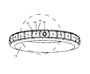
Figure I A shows ring 10 with markings 20 as indicators for future
placement of gemstones on an inner surface of ring 10. Figure lA also shows
stamping
area 40 which may include text, symbols or other graphics, such as personal
engravings,
indicators of origin or material composition of ring 10.
Ring 10 may be made of precious or non-precious material, including but
not limited to platinum alloy, gold alloy, palladium alloy, silver alloy, or
another alloy.
Ring 10 may have a setting (not shown) to accommodate additional gemstones.
As shown in more detail in Fig. 1 B, markings 20 may identify the location
of gemstones and may be a symbol, such as a circle, or other identifier.
Markings 20 may
be provided to identify to jewelers the location and optionally the size or
type of
gemstone that may occupy the location in the future. Markings 20 may be sized
or
5
CA 02801068 2012-11-28
WO 2011/155940 PCT/US2010/038163
otherwise indicate or correspond to sizes of gemstones to be set. Fig, I B
shows markings
20-4 and 20-5. Marking 20-4 includes center point marking 24-A that may
identify a
center point of placement of a gemstone, and outer circle marking 22-A that
may indicate
a size of a gemstone that may occupy that location. That is, outer circle
marking
diameter 26-A may be a size approximately equal to the gemstone to occupy that
location. In one non-limiting example, a location for an approximately 0.7 mm
gemstone may be identified by marking 20-4 having center point marking 24-A
placed at
the center of the preferred gemstone location, with outer circle marking 22-A
having
outer circle marking diameter 26-A of approximately 0.7 mm.
Alternatively, outer circle marking diameter 26-A may be smaller or larger
than the size of the gemstone to occupy that location. In other aspect,
multiple outer
circles may be used or no outer circle marking 22-A may be present.
Fig. I B also shows distance from outer circle to ring edge 28-A for
marking 20-4. Fig. 1 B further shows second marking 20-5, for a gemstone
larger than
intended for marking 20-4, as illustrated by outer circle marking diameter 26-
B, which is
larger than 26-A, and distance from outer circle to ring edge 28-B, which is
smaller than
28-A.
Fig. 1B further shows distance 30 between outer circle markings 22-A and
22-B, as well as distance 32 between center point markings 24-A and 24-B. Ring
width
34 is also shown.
It will be understood that marking 20 may be other characters, symbols or
graphics, such as a plus sign ("+") or asterisk ("'"). Marking 20 may be an
indentation,
engraving, or scoring.
6
CA 02801068 2012-11-28
WO 2011/155940 PCT/US2010/038163
Figure 2 shows an expanded view of a portion of an inner surface of ring
with a pattern of markings 20-1. through 20-12. The pattern shows four,
smaller
markings 20-1 to 20-4 followed by a fifth, larger marking 20-5. The pattern
repeats for
four, smaller markings 20-6 to 20-9 followed by marking 20-10, and this
pattern may be
5 repeated around inside of ring 10. In this non-limiting example, one smaller
gemstone
may be purchased and set at marking 20-1 to commemorate an event, such as an
anniversary. Additional smaller gemstones may be purchased and set at markings
20-2 to
20-4 each year for four years. At the fifth year, a larger gemstone may be
purchased and
set at marking 20-5 to commemorate a fifth anniversary. Markings 20-6 to 20-9
indicate
10 the position and size of smaller gemstones that may be purchased and set
during years six
through nine, while marking 20-10 indicates the position and size of a larger
gemstone
that may be purchased and set during year ten. Continuing with this example,
larger
gemstones may be purchased and set at the fifteenth and twentieth
anniversaries, with
smaller gemstones used in the intervening years. In yet another aspect,
gemstones and
markings may be the same size.
Views of ring 10 having 26 gemstones of two sizes and one stamping area
are shown in Figs. 3A, 3B, and 4. Figure 4 shows a cross-sectional top view of
ring 10
exposing embedded gemstones in the positions.
Views of ring 10 having 26 gemstones of two sizes and two stamping
areas are shown in Figs. 5A, SB, and 6. Figure 7 shows exemplary positions and
sizes of
gemstones for three ring sizes, each having 26 gemstones of two sizes and two
stamping
areas. In Fig. 7, all rings are 2.0 mm bands, small gemstones (for example, 20-
1 to 20-4)
are 0.8 mm, and large gemstones (for example, 20-0; 20-5; and 20-10)are 1.10
mm. Size
7
CA 02801068 2012-11-28
WO 2011/155940 PCT/US2010/038163
3 rings with this configuration have all gemstones set 0.559 mm apart, with
4.382 mm
stamping areas. Size 8 rings with this configuration have all gemstones set
0.968 mm
apart, with 5.648 mm stamping areas. Size 1.3 rings with this configuration
have all
gemstones set 1.385 mm apart, with 6.913 mm stamping areas.
Views of ring 10 having 26 gemstones of two sizes and one stamping area
with gemstone are shown in Figs. 8A, 8B, and 9.
Views of ring 10 having 26 gemstones of one size and one stamping area
are shown in Figs. 10A, l OB, and 11. Views of ring 10 having 26 gemstones of
one size
and two stamping areas are shown in Figs. 12A, 12B, and 13. Views of ring 1.0
having
26 gemstones of one size and one stamping area with gemstone are shown in
Figs. 14A,
14B, and 15.
Views of ring 10 having 51 gemstones of one size and one stamping area
are shown in Figs. 16A, 16B, and 17. Views of ring 10 having 51 gemstones of
two sizes
and one stamping area are shown in Figs. 18A, 18B, and 19. It will be
understood that
other arrangements of gemstones and stamping areas are available.
It will be understood that the number of gemstones in ring 10 may be any
number. In two of the non-limiting examples discussed in more detail, 26
gemstones and
51 gemstones are shown. In those examples, one gemstone may be set to
commemorate
a wedding day, and the remaining 25 or 50 gemstones may be set to commemorate
yearly
anniversaries for the following 25 or 50 years respectively.
Ring Design and Manufacture
Figure 21 shows a flowchart for a process for marking a ring for
placement of 51 gemstones. A user may input finger size at Step 100 and width
of ring
8
CA 02801068 2012-11-28
WO 2011/155940 PCT/US2010/038163
at Step 105. Step 110 indicates this process will determine placement of 51
gemstones. If a user selects that all gemstones are the same size at Step 115,
then the
process will. use the placement formula in Step 125.
In Step 125, the process subtracts a minimum size of stamping area 40
5 from finger size circumference, and the difference is the available gemstone
area. In one
example, minimum size of stamping area 40 may be approximately 8.0 mm. The
process
multiplies the number of spaces between gemstones by the minimum space between
gemstones then subtracts that amount from the available gemstone area to
determine a
preliminary largest possible gemstone size. In one example, the minimum space
between
10 gemstones may be 0.1 mm, and the number of spaces between gemstones for a
51
gemstone ring may be 50 spaces for a ring having one stamping area 40, or may
be 49
spaces for a ring having two stamping areas 40. Gemstones having diameters
smaller
than the preliminary largest possible gemstone size may be used (or required)
with the
remaining area added to stamping area 40 in Step 135 or added to and/or
distributed
among the spaces between gemstones. In one aspect, when 51 gemstones of one
size are
selected, due to the generally smaller diameter of the gemstones that will fit
in along an
inner surface of a ring, the size of gemstone diameter may not be limited by
the ring
width.
If a user selects that the gemstones will be of two sizes at Step 120, then
the process will use the placement formula in Step 130. In Step 130, the
process
subtracts a minimum size of stamping area 40 from finger size circumference,
and the
difference is the available gemstone area. In one example, minimum size of
stamping
area 40 may be approximately 8 mm.
9
CA 02801068 2012-11-28
WO 2011/155940 PCT/US2010/038163
The process multiplies the number of locations for smaller gemstones by
the minimum smaller gemstone size, then subtracts that amount from the
available
gemstone area to determine a first quantity. In one example, a 51 gemstone
ring may
have 40 smaller gemstones and minimum smaller gemstone size of 0.6 mm. The
process
divides the first quantity by the number of locations for larger gemstones to
determine a
larger gemstone size. In one example, a 51 gemstone ring may have 11 larger
gemstones.
It may be desirable to have larger gemstones at least 0.3 mm larger than
smaller
gemstones. Depending on factors, it may be possible to increase the smaller
and larger
gemstone sizes.
In another aspect, gemstone sizes may be determined using a
predetermined minimum space between gemstones and a predetermined difference
in
gemstone size between smaller and larger gemstones. In one non-limiting
example,
minimum space between gemstones may be 0.1 mm and predetermined difference in
gemstone size may be 0.3 mm. The number of smaller gemstones times the minimum
space may be added to the number of larger gemstones times the minimum space
plus
predetermined difference, and this quantity subtracted from the available
gemstone area
to create a remaining area. The remaining area may be divided by the number of
spaces
between gemstones to produce a preliminary largest possible gemstone size for
the
smaller stones. The gemstone sizes may be adjusted to maintain relative size
difference
between the larger and smaller stones.
After Step 125 or Step 130, the process proceeds to Step 135 where the
size of stamping area 40 may be increased by any additional space available
after
determining gemstone size above.
CA 02801068 2012-11-28
WO 2011/155940 PCT/US2010/038163
In Step 140, a style of stamping area 40 is implemented. In this example,
one of three styles may be implemented. Step 145 indicates one stamping area
40. Step
150 indicates one stamping area 40 with one gemstone located within the
stamping area
40. Alternatively, the total stamping area may be distributed across multiple
stamping
areas 40. Step 155 indicates two stamping areas, which may be contiguously
arranged or
may be arranged otherwise, for example, on opposite sides of ring.
If one gemstone size was selected in Step 115, then the process proceeds
to Step 160, where gemstone parameters and placement are determined. The
process will
calculate the setting depth of the gemstones. The setting depth may be
calculated to
ensure the gemstone table is a predetermined depth, for example, 0.05 mm,
below the
inner surface of the ring 10. So doing may prevent the gemstones from damage
and
result in a more comfortable fit for the wearer.
If two gemstone size was selected in Step 120, then the process proceeds
to Step 165, where the process calculates setting depth. The setting depth may
be
calculated to ensure the gemstone table of the larger gemstones are a
predetermined
depth, for example, 0.05 mm, below the inner surface of the ring 10. As shown
in Figure
20, a smaller gemstone 20-4 may be set at a depth 52 such that the girdle of
the smaller
gemstone 20-4 is aligned with the girdle of a larger gemstone 20-5, as
illustrated by the
dashed horizontal line. For this to occur, depth 52 of smaller gemstone 20-4
may be
larger than depth 50 of larger gemstone 20-5.
After Step 160 or Step 165, the process proceeds to Step 170 where the
gemstone position is calculated. In this step, the process generates locations
of the
11
CA 02801068 2012-11-28
WO 2011/155940 PCT/US2010/038163
gemstones along the inner surface of the ring and generates measurements of
those
locations in degrees.
Once these calculations are performed, the locations may be marked on an
inner surface of the ring 10.
Figure 22 shows a flowchart for a process for marking a ring for
placement of 26 gemstones. As described above, user may input finger size
(Step 100)
and width of ring 10 (Step 105). Step 200 indicates this process will
determine
placement of 26 gemstones.
In Step 205, the process determines the stamping area. Due to the smaller
quantity of gemstones in the 26 gemstone ring, there may be more space for
stamping
area 40 and spacing between gemstones. The stamping area 40 may be calculated
using
the minimum stamping area, for example, 8.0 mm from gemstone girdle to
gemstone
girdle, for a small ring size, then extrapolated for larger ring sizes as
shown in Fig, 7. As
shown in Fig. 7, total stamping area may be spread across two stamping areas
40 located
opposite one another or elsewhere on the inner surface of the ring 10.
In Step 210, a style of stamping area 40 is implemented. In this example,
one of three styles may be implemented. Step 215 indicates one stamping area
40. Step
220 indicates one stamping area 40 with one gemstone located within the
stamping area
40. Alternatively, the total stamping area may be distributed across multiple
stamping
areas 40. Step 225 indicates two stamping areas, which may be contiguously
arranged or
may be arranged otherwise, for example, on opposite sides of ring.
If a user selects that all gemstones are the same size at Step 230, then the
process may use the gemstone size selection in Step 240 for bands having width
2.0 mm
12
CA 02801068 2012-11-28
WO 2011/155940 PCT/US2010/038163
through 3.0 mm or the process may use the gemstone size selection formula in
Step 245
for bands having width 3.5 mm and larger.
In Step 240, maximum gemstone sizes may be selected by keeping a
minimum distance, for example, of 0.4 mm, from gemstone girdle to the edge of
the ring.
This is to allow the gemstone to fit and be set within the ring and prevent
damage to the
ring. Maximum gemstone sizes may also be selected so that there is at least
0.1 mm
girdle-to-girdle between gemstones.
In Step 245, because the larger width of the ring, maximum gemstone
sizes may be selected so that there is at least 0.1 mm girdle-to-girdle
between gemstones.
Once gemstone sizes for one gemstone size arrangements have been
determined, the process moves to Step 260.
In Step 260, the process subtracts a stamping area size from finger size
circumference, then divides that amount by the number of spaced between
gemstones, in
this case 25, yielding the maximum gemstone size subject to rules laid out in
Steps 245
and 245. The process then equally spaces the gemstones leaving a predetermined
distance between the gemstones, for example, 0.1 mm. The process will
calculate the
setting depth of the gemstones. The setting depth may be calculated to ensure
the
gemstone table is a predetermined depth, for example, 0.05 mm, below the inner
surface
of the ring 10. So doing may prevent the gemstones from damage and result in a
more
comfortable fit for the wearer.
If a user selects that the gemstones will be of two sizes (Step 235), then
the process will use the gemstone size selection in Step 250 for bands having
width 2.0
mm (all finger sizes) or 3.0 mm and up (finger sizes 4-7) or the process will
use the
13
CA 02801068 2012-11-28
WO 2011/155940 PCT/US2010/038163
gemstone size selection formula in Step 255 for bands having width 3.0 mm and
larger
(finger sizes 7.5 and up).
In Step 250, the size difference between the small gemstone and large
gemstone may be 0.3 mm for 2.0 mm. ring widths and maximum gemstone size may
be
restricted by width of the ring that must allow 04 mm from girdle to ring
edge. For
example, a ring of 2.0 mm width may have a maximum gemstone size of 1.1 mm
allowing for 0.4 mm at top and bottom of gemstone, plus 0.1 mm to allow for
any
cylindrical (non-square) ring shape. For rings having 3.0 mm width and up and
finger
sizes 4 though 6.5, the size difference between the small gemstone and large
gemstone
may be 0.3 mm., with small gemstones at 1.5 mm maximum and large gemstones 1.8
mm
maximum. For rings having 3.0 mm width and up and finger size 7, the size
difference
between the small gemstone and large gemstone may be 0.4 mm, with small
gemstones at
1.5 mm maximum and large gemstones 1.9 mm maximum.
In Step 255, for finger sizes 7.5 and up, the size difference between the
small gemstone and large gemstone may be 0.3 mm for small gemstones smaller
than and
equal to 1.5 mm, and the difference may be 0.4 min for small gemstones larger
than 1.5
mm. Once gemstone sizes for two gemstone size arrangements have been
determined,
the process moves to Step 265.
For rings of 3.0 mm width and finger size 9 and up, gemstone size may be
restricted by width of the ring that must allow 0.4 mm from girdle to ring
edge. For rings
of 3.0 mm width and below finger size 9 and for rings of width greater than
3.0 mm,
gemstone size is restricted by minimum 0.1 mm girdle-to-girdle proximity.
14
CA 02801068 2012-11-28
WO 2011/155940 PCT/US2010/038163
In Step 265, the process subtracts a size of stamping area 40 from finger
size circumference, and the difference is the available gemstone area. In one
example,
minimum size of stamping area 40 may be approximately 8 mm.
The process multiplies the number of locations for smaller gemstones by
the minimum smaller gemstone size, then subtracts that amount from the
available
gemstone area to determine a first quantity. In one example, a 26 gemstone
ring may
have 20 smaller gemstones and minimum smaller gemstone size of 0.6 mm. The
process
divides the first quantity by the number of locations for larger gemstones to
determine a
larger gemstone size. In one example, a 26 gemstone ring may have 6 larger
gemstones.
It may be desirable to have larger gemstones at least 0.3 mm larger than
smaller
gemstones. Depending on factors, it may be possible to increase the smaller
and larger
gemstone sizes.
In this step, the process also calculates setting depth. The setting depth
may be calculated to ensure the gemstone table of the larger gemstones are a
predetermined depth, for example, 0.05 mm, below the inner surface of the ring
10. The
smaller gemstones are set at a depth such that the girdle of the smaller
gemstone is
aligned with the girdle of the larger gemstone, as shown in Fig. 20.
After Step 160 or Step 165, the process proceeds to Step 170 where the
gemstone position is calculated. In this step, the process generates locations
of the
gemstones along the inner surface of the ring and generates measurements of
those
locations in degrees.
Once these calculations are performed, the locations may be marked on an
inner surface of the ring 10.
CA 02801068 2012-11-28
WO 2011/155940 PCT/US2010/038163
Figure 23 is a flowchart of the process of marking the ring 10. In Step
300, the process may receive as input, stamping area size and type, marking
locations,
marking types, and marking sizes for a specific finger size into control
software. In one
aspect, software such as Visual LaserStar Write (VLW) may be used control a
laser
engraving system such as a Crawford-LaserStar Technologies 6-watt Marking
Laser,
3700 Series. In other aspects, marks may be made by a CNC machine. In Step
305, ring
may be inserted into the laser engraving system and the system may engrave the
markings. In Step 310, graphics, such as text, may be optionally engraved in
one or more
the stamping areas.
10 Some time after Step 305, at Step 315, the ring 10 may be sent to an
authorized individual or business to set a gemstone in ring 10. At Step 320, a
milling
machine may be used to drill a hole at one or more markings to accommodate a
gemstone. The markings, including marking size, type, and locations, may be
used as a
guide for drilling the hole size and location. A gemstone may be set into the
hole. At
Step 325, ring 10 may be returned to the owner and the process may be repeated
upon the
next event or anniversary.
Numerous additional modifications and variations of the present
disclosure are possible in view of the above teachings. It is therefore to be
understood
that within the scope of the appended claims, the present disclosure may be
practiced
other than as specifically described herein. -
16