Note: Descriptions are shown in the official language in which they were submitted.
CA 02801072 2016-11-03
THERMOFORMING SYSTEM, THERMOFORMED PRODUCT, AND METHOD OF
THERMOFORMING
FIELD OF THE INVENTION
This invention relates to shaping heated polymeric materials in a mold and
more particularly, although not necessarily exclusively, to heating selected
areas of the
materials to forming temperatures while not fanning other areas of the
materials.
BACKGROUND OF THE INVENTION
Conventional thermofoiming involves heating a polymer sheet to a pliable
forming temperature (which depends at least in part on the type of sheet being
heated),
forming the sheet to a specific shape on a mold, and thereafter trimming
unformed
portions of the sheet to create a useful product. The sheet, sometimes
referred to as
"film" when thin gauges or certain types of materials are formed, is typically
heated in an
oven to the forming temperature so that it may be stretched into or onto a
mold and then
cooled to retain a finished shape. During the heating process, the entire
sheet of material
is heated to the forming temperature. Portions of the sheet that are not
formed are usually
referred to as "trim" and not reused until after further processing.
U.S. Patent No. 4,878,826 to Wendt, the entire contents of which are
incorporated herein by this reference, is one of many patents disclosing
apparatus for
thermoforming articles from sheets of plastic material. The apparatus of the
Wendt patent
may include both male and female molds together with a heating means and
evacuation
equipment. One such heating means is described as being hot oil circulating
through an
associated manifold such that it crystallizes a sheet of plastic material. See
Wendt, col.
10,11. 9-12. According to the Wendt patent, the sheet also may be pre-heated
to 10-15%
crystallization before entering the mold. See id., col. 12, IL 50-57. Indeed,
over-
'
CA 02801072 2012-11-28
WO 2011/152964 PCT/US2011/036001
crystallization of the sheet apparently is an issue with the apparatus of the
Wendt patent,
requiring cold air to be injected into various mold cavities. See id., col.
13, 11. 53-65.
Thermoforming a plastic sheet necessarily distorts it. However, in some
circumstances distortion of certain portions of a sheet is undesirable. As an
example,
distortion of portions of a sheet containing printing or art work may render
them
unintelligible or, at minimum, diminish their aesthetic appeal. Consequently,
conventional thermoforming requires pre-printing of text and art in a
distorted form so
that the further distortion caused by the thermoforming can counteract the pre-
distortion
and, at least theoretically, produce intelligible images. Thus, providing
apparatus and
methods that would allow thermoforming of selected portions of a plastic sheet
while
avoiding distortion of other portions of the sheet thus would be a beneficial--
albeit
difficult¨achievement.
SUMMARY OF THE INVENTION
The present invention accomplishes this desired result. Notwithstanding its
use of an integral sheet of polymeric material, the present invention allows
heating and
forming of only selected portions of the material. By contrast, unformed
portions of the
material remain substantially undistorted and thus may contain undistorted
printing, art
work, or other text, symbols, or information without concern as to whether
intelligibility
of the information will be degraded during the forming process. Even if
information is
not present in unformed regions of a sheet, the mere fact that the unformed
regions may
retain their original shapes (typically but not necessarily flat) and
thicknesses permits a
broader range of products to be created. Further, apparatus and methods of the
present
invention admit productive use of the vast majority of each sheet (e.g. 95% in
some
cases), so that little trim is created when products are formed.
In at least some embodiments of the invention, energy-absorbing or -
reflecting material may be employed to limit heat or other energy transferred
to the
polymer sheets. Such material may be in the form of metallic or other plates
having
simple or complex shapes. The plates may include cut-outs so that heat or
other energy
may be transferred efficiently to areas of a sheet that is to be thermoformed.
Various
embodiments of the invention also may utilize controllable banks of heaters to
allow
variable heating of the molds themselves.
2
CA 02801072 2012-11-28
WO 2011/152964 PCT/US2011/036001
It thus is an optional, non-exclusive object of the present invention to
provide apparatus and methods for selectively thermoforming integral polymeric
materials.
It is another optional, non-exclusive object of the present invention to
provide apparatus and methods for thermoforming portions of a polymer sheet
while not
forming, or otherwise materially distorting, other portions of the sheet.
It is an additional optional, non-exclusive object of the present invention to
provide apparatus and methods permitting text, art work, or other information
to be
printed on to-be-formed material in an undistorted manner yet remain
intelligible post-
forming.
It is also an optional, non-exclusive object of the present invention to
provide apparatus and methods for selective thermoforming including use of
mechanical
heat-transfer barriers.
It is yet another optional, non-exclusive object of the present invention to
provide apparatus and methods in which the heat-transfer barriers are in the
form of plates
having cut-outs through which heat may readily pass.
It is a further optional, non-exclusive object of the present invention to
provide apparatus and methods for selective thermoforming using controllable
banks of
heaters to allow variable heating of the molds themselves.
It is, moreover, an optional, non-exclusive object of the present invention
to provide apparatus and methods for selective thermoforming while limiting
the amount
of trim.
Other objects, features, and advantages of the invention will be apparent to
persons skilled in the relevant art with reference to the remaining text and
the drawings of
this application.
BRIEF DESCRIPTION OF THE DRAWINGS
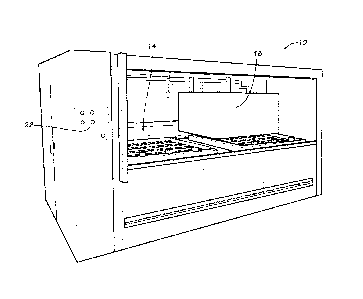
FIG. 1 is a perspective view of exemplary thermoforming apparatus useful
as part of or in connection with the present invention.
FIG. 2 is a perspective view of a portion of a mold comprising part of the
apparatus of FIG. 1.
3
CA 02801072 2012-11-28
WO 2011/152964 PCT/US2011/036001
FIG. 3 is a close-up view of part of the mold portion of FIG. 2 illustrating
especially various plugs protruding upward from its surface onto which a
formable sheet
may be placed.
FIG. 4 is a generally elevational view of an exemplary heat-sinking plate
that may comprise part of the present invention.
FIG. 5 is a close-up view illustrating a formed polymer sheet contacting the
mold part of FIG. 3.
FIG. 6 is a generally elevational view of an exemplary product
thermoformed in the manner of the present invention.
FIG. 7 is a generally side (edge) view of an exemplary product similar to
that shown in FIG. 6.
FIGS. 8A-C are various views of a plug consistent with FIG. 3.
DETAILED DESCRIPTION
Depicted in FIG. 1 is exemplary thermoforming apparatus 10. Apparatus
may be a conventional thermoforming machine, any number of which are available
commercially. Preferably included as part of apparatus 10 are mold 14 (see
also FIGS. 2-
3) and heater 18. A computerized controller including actuating means 22 may,
if
desired, be connected to heater 18 to control aspects of its operation.
Actuating means 22
may comprise one or more manual switches as shown in FIG. 1. Those skilled in
relevant
fields will recognize, however, that other manners of actuating heater 18 may
be
employed instead and that no controller is required.
Heater 18 preferably is positionable above mold 14 so as to supply heat
only to one side of the mold 14, which itself may be heated. FIGS. 2-3 show
aspects of
an exemplary version of mold 14, which preferably (although not necessarily)
is made of
aluminum. Alternatively, mold 14 may be of composite type with both male and
female
components. As illustrated particularly in FIG. 3, mold 14 may comprise a
generally
planar upper surface 26 from which one or more plugs 30 protrude. In use of
apparatus
10, plugs 30 function as three-dimensional objects about which sheets of
polymer
material are formed.
FIGS. 8A-C illustrate aspects of an exemplary plug 30. Plug 30 may, if
desired, be shaped generally as a cylinder and include section 31 comprising
upper
4
CA 02801072 2012-11-28
WO 2011/152964 PCT/US2011/036001
surface 32 together with side 33. Formed in side 33 may be one or more notches
35. At
least two, and preferably three (or more) such notches 35 are incorporated
into side 33,
with the notches 35 preferably (although not necessarily) being angularly
spaced evenly
about the circumference of plug 30. For example, if plug 30 includes three
notches 35,
each notch 35 may be spaced one hundred twenty degrees (120 ) from adjacent
notches
35. As depicted in the side view of FIG. 8B, notches 35 need not extend
completely to
upper surface 32--although they may do so if desired.
Also detailed in FIGS. 2-3 as part of mold 14 are clamps 34 and alignment
pins 38. Clamps 34 surround some or all of perimeter 42 of mold 14 and retain
to-be-
formed material in place relative to upper surface 26. Pins 38, which like
plugs 30 extend
upward from upper surface 26, facilitate alignment of the to-be-formed
material relative
to the plugs 30.
An exemplary heat sink 46 appears in FIG. 4. Sink 46 may be sized and
shaped in any appropriate manner and may of any suitable heat-absorbing (or -
reflecting)
material. Preferably, however, sink 46 conforms to the shape of the
corresponding mold
or surface to be heated; as shown in FIG. 4, exemplary sink 14 is in the form
of a
generally rectangular, generally planar aluminum plate. Consistent with the
present
invention, sink 46 may include one or more cut-outs 50 through its depth, each
of which
preferably is approximately the size and shape of an associated plug 30. Sink
46
additionally may include openings 54 for receiving alignment pins 38.
Apparatus 10 may be utilized with any thermoformable material. For
certain purposes identified herein, however, the material beneficially is
polyethylene
terephthalate ("PET"), a polymeric plastic resin. Additionally beneficial for
various of
these purposes is that the PET be transparent. Again, though, the
thermoformable
material need not necessarily be clear or transparent, nor need it be PET. For
ease of
handling, the material advantageously may be preformed into a generally planar
sheet of
predetermined size and shape.
Among products usefully created using the present inventive techniques are
plastic display holders for coins or souvenirs. Collector-quality versions of
such holders
may, and indeed typically, include color printing, art work, and text in
unformed regions.
By contrast, formed regions--into which coins are placed--preferably remain
clear so as
not to impede viewing of the coins. In some cases the holders may be combined
back-to-
CA 02801072 2012-11-28
WO 2011/152964 PCT/US2011/036001
back or placed within clear housings for further protection of the coins.
Objects other
than coins or souvenirs may be displayed, and products other than display
holders may be
created, however, as should be apparent to persons skilled in the art.
According to at least one method of the present invention, mold 14 may be
heated to a preset temperature. The temperature may be selected so as to allow
thermoformable material to be formed by the mold 14 and so as to be sufficient
to remove
heat from the material. Preferably, however, the selected temperature is such
that
warping or chill marks will not be formed on or in the material.
After mold 14 is heated adequately, a sheet of material containing
undistorted color printing, art work, or text (or combinations thereof) may be
laid onto
upper surface 26 of mold 14. For at least some display holders, up to six
colors may be
printed on each side of the sheet, with opaque material (text and art work)
then printed
over the printed colors. Of course, any or all of the printed matter may be
omitted if not
needed in the final product. Nevertheless, when present, the printed matter
need not be
pre-distorted, as it is not subject to material distortion during the forming
process.
Assuming the above-described coin display holders are to be created, the
sheet preferably contains openings through its depth for receiving alignment
pins 38, with
the openings themselves positioned so that, when pins 38 are received,
unprinted (clear)
areas of the sheet are positioned on upper surface 26 atop some or all of
plugs 30.
Clamps 34 may then be employed to secure the periphery of the sheet against
upper
surface 26. Thereafter, sink 46 may be placed atop the sheet, with its
openings 54
likewise receiving alignment pins 38 and at least some of its cut-outs 50
aligned with
clear areas of the sheet. So placing sink 46 effectively sandwiches the sheet
between
mold 14 and sink 46, precluding its longitudinal and lateral movement.
Following placement of the sheet relative to mold 14, heater 18 is
repositioned closely above sink 46 and activated for a selected period of
time.
Continuing with the display holder example, heater 18 may be activated for
approximately thirty seconds. Heat or other energy from heater 18 transfers to
sink 46
and, where cut-outs 50 in sink 46 exist, to (clear) areas of the sheet
therewith aligned,
where it is absorbed by the polymeric material.
As the exposed areas of the sheet absorb sufficient heat to reach their
forming temperatures, mold 14 is evacuated so as to stretch (form) the
material around
6
CA 02801072 2012-11-28
WO 2011/152964 PCT/US2011/036001
plugs 30. Heater 18 then may be repositioned away from mold 14, the formed
sheet of
material may be allowed to cool, and sifflc 46 may be removed so as to expose
the sheet of
material. FIG. 5 illustrates material 58 in this exposed state, with the
material 58
including (in this example) both unformed portions 62 and formed portions 66.
The sheet
of material 58 thereafter may be removed from mold 14 and, if appropriate,
divided into
display holders, examples of which (designated 70A and 70B) are depicted in
FIGS. 6-7.
Moreover, because only the periphery of material 58 was clamped during the
forming
process and need be trimmed, the vast remaining majority of the material 58
was
available to create products. The processes of the invention may be repeated
for any
number of sheets of material.
Exemplary holder 70A includes six formed portions 66, five generally
circular in shape and configured to receive a coin for display (see, e.g.,
FIG. 7). In FIG.
6, the sixth formed portion (66A) of holder 70A includes embossed letters
"USA." By
contrast, many of unformed portions 62 include color printing, with additional
text and art
work 74 printed thereon. Distortion-free text spelling "TEST" in printed areas
of
unformed portions 62 renders apparent the fact that the portions 62 did not
distort while
portions 66 were forming. Because holder 70A is merely one of many examples of
holders capable of being made by the present invention, in no way is the
invention limited
to holders having any particular number or type of formed portions 66 or
unformed
portions 62. (Further, although not presently preferred, any of portions 66
may include
distorted printing that becomes more legible when portions 66 are formed.)
Because plugs 30 may include notches 35 against which material 58 may
be fashioned, formed portions 66 may include a corresponding number of "crush
tabs" or
"click-in features" protruding inward into the coin-receiving regions. These
tabs provide
some tolerances for portions 66. If, for example, a portion 66 is slightly
larger in
diameter than a to-be-received coin, the coin, when inserted, may
(frictionally) bear
against the inwardly-protruding tabs to be retained in position. If unneeded,
the tabs will
be crushed or otherwise deformed upon insertion of the coin so as not to
impede its
retention.
The foregoing is provided for purposes of illustrating, explaining, and
describing embodiments of the present invention. Modifications and adaptations
to these
7
CA 02801072 2012-11-28
WO 2011/152964
PCT/US2011/036001
embodiments will be apparent to those skilled in the art and may be made
without
departing from the scope or spirit of the invention.
8