Note: Descriptions are shown in the official language in which they were submitted.
MEDICATION INFUSION KIT
FIELD OF THE INVENTION
[0002] The present invention relates generally to the field of
medicine and therapeutic
medication delivery, and more particularly to self-contained parenteral
infusion kits.
BACKGROUND
[0003] The current practice of intravenous medication infusion often
involves a relatively
complicated process of assembling several sterile parts and performing
appropriate dosing
calculations. Further, where more refined dosing is requited or desired,
expensive electronic
infusion pumps are often utilized. Infusion pumps offer certain advantages,
but drawbacks
include cost, the need for a power source, maintenance requirements,
susceptibility to adverse
environmental conditions, and perhaps most importantly, require requisite
knowledge to use
safely and effectively. There are several circumstances where less expensive
yet automated
intravenous infusion systems are ideal.
[0004] Intravenous infusions are now more commonly performed in
prehospital settings
where smaller, lighter, and self-powered systems enjoy a distinct advantage.
In the prehospital
setting, equipment storage space is minimal, power may be nonexistent, and
equipment must be
portable and able to withstand the elements. Yet, emerging data suggests that
early prehospital
use of certain medications may improve outcome_ For example, the early
administration of
Progestins may improve patient clinical outcome following traumatic brain
injury and stroke.
Progestins, however, must be infused over a significant duration and should be
started early.
This ideal window exists at a time when a single paramedic is responsible for
performing
1
CA 2801200 2017-09-12
CA 02801200 2012-11-29
WO 2011/159714 PCT/US2011/040376
multiple tasks to stabilize the patient, limiting the time available to manage
an intravenous
medication system.
[0005] Furthermore, administering intravenous medication in other
prehospital settings,
such as military environments, produces still greater challenges. In addition
to the difficulties
encountered above, personnel may be scarce, and patients can suddenly and
frequently
outnumber trained clinical staff. In some locations, the highest level of
immediate care is quite
commonly a field medic. Further, calamitous events such as natural disasters,
war, and
insurrection may displace a vast number of people and commonly degrade,
destroy, and
overwhelm the local hospital system, making medication infusion using standard
pumps
impossible.
[0006] Yet, developing a viable portable intravenous system poses
challenges. Infusion
pumps are typically too complicated and expensive to dedicate for use with a
single medication
.. or make disposable. Traditional pre-packaged and sealed medical and
surgical kits have
limitations. For example, medications are commonly required in kits, and when
a medication's
shelf life expires, a typical kit is no longer useful for patient care and
frequently must be
destroyed. This practice is expensive, wasteful, and presents logistical
burden of accounting for
and managing medical waste.
[0007] Therefore, what is needed is a relatively small, portable, self-
contained, and self-
powered system which can reliably deliver an intravenous infusion safely and
effectively. What
is further needed is a kit which contains medications permitting more rapid
setup and delivery of
an intravenous system, while allowing medications to be inspected and replaced
without
exposing the remainder of the kit.
SUMMARY
[0008] Aspects of the present invention disclose a sterile or non-
sterile sealed infusion kit
which may be recyclable or disposable, and which may be operated without an AC
electric
power source. Embodiments of the present invention include a prepackaged
infusion kit which
may be utilized with or without prepackaged medicaments. Other embodiments
describe
2/13
CA 02801200 2012-11-29
WO 2011/159714 PCT/US2011/040376
prepackaged medications contained with the infusion system. Further still,
other aspects of the
invention disclose a prepackaged system containing specific medication dosages
allowing for a
more rapid, efficient, and safe infusion. Other aspects of the invention
disclose a variety of self-
powered force applicators to drive medication from the inventive infuser into
the patient's
system. Other aspects of the invention describe a kit containing perishable
medications or
adjunctive solutions wherein a portion of the kit may be opened to expose the
perishable
substances so they may be changed without opening the remainder of the kit.
BRIEF DESCRIPTION OF THE DRAWINGS
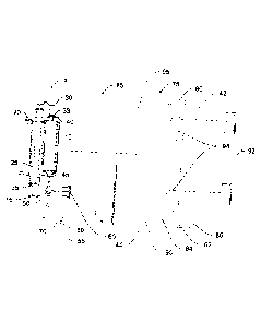
[0009] FIG. 1 is a partially exploded perspective view of an
embodiment vacuum drive
infuser with an embodiment packaging.
[0010] FIG. 2 is a partially exploded perspective view of an
embodiment spring-drive
infuser with an embodiment packaging.
[0011] FIG. 3 is a partially exploded perspective view of an embodiment
coaxial vacuum
powered syringe with an embodiment packaging.
[00] 2] FIG. 4 is a partially exploded perspective view of an
embodiment spring-driven
infuser, with embodiment packaging.
[0013] FIG. 5 is a partially exploded perspective view of an
embodiment gas-driven
infuser, with embodiment packaging.
[0014] FIG. 6 is a partially exploded perspective view of an
embodiment gas-driven
infuser, with embodiment packaging.
[0015] FIG. 7 is a partially exploded perspective view of an
embodiment elastomeric
balloon, with embodiment packaging.
[0016] FIG. 8 is a partially exploded perspective view of an embodiment
motor driven
infuser with a portion of threaded tube removed to expose worm screw, with
embodiment
packaging.
[0017] FIG. 9 is a perspective view of an embodiment packaging.
3/13
CA 02801200 2012-11-29
WO 2011/159714 PCT/US2011/040376
DETAILED DESCRIPTION
[0018] Turning now to FIG. 1, infuser 5 may be comprised of a
medication holding
vessel, such as a syringe 10 coupled to chamber 15 by clamp 20. Driver 25 is
attached to or
integrally formed with a portion of handle 30 disposed within chamber 15 and
an airtight seal is
formed between sliding sealed piston 35, mounted on the end of driver 25, and
the inner surface
of chamber 15. When handle 30 is drawn back, piston 35 increases a vacuum
force within that
portion of chamber 15 distal to piston 35. In an alternative embodiment.
handle 30 is shaped to
define a platform 33 which makes contact with the most proximal surface of
plunger 40. In an
alternative embodiment, a portion of handle 30 is shaped to form plunger 40
which is in a fluid
.. tight disposition within syringe 10. Clamp 20 holds syringe 10 and chamber
15 tightly together
in place to prevent movement of syringe 10 relative to chamber 15.
[0019] Functionally, the user places medication vial 92 into standard
vial adapter 60,
during which sharp center spike 65 penetrates the membrane of vial 92. A
standard medical
stopcock 50 is then oriented to allow the medicament in vial 92 to flow into
syringe 10 during
standard aspiration of plunger 40, after first rotating handle 30 so that
platform 33 and plunger
40 are no longer in contact. After the desired amount of medicament has been
aspirated into
syringe 10. stopcock 50 is then adjusted to eventually permit the flow of
medicament in syringe
10 out of syringe opening 45 and preferably into infusion tubing 70. It should
be noted that
stopcock 50 may be a two-way, three-way, four-way, or six-way stopcock.
[0020] The practitioner then withdraws infuser handle 30 wherein
piston 35 is drawn
back to produce or increase a vacuum in chamber 15. Next, handle 30 may be
rotated to allow
driving platform 33 to make contact with and push downwardly on syringe
plunger 40. Handle
30 is then released and the force generated by piston 35 sliding fowardly to
fill the vacuum
causes driver 25 and handle 30 to likewise move forwardly and in so doing,
drives platform 33 to
depress plunger 40. As plunger 40 moves forwardly within syringe 10, a
flowable medicament
may flow from syringe opening 45 and out of syringe 10 into any attached
intravenous tubing 70
or other route of intravenous administration.
4/13
CA 02801200 2012-11-29
WO 2011/159714 PCT/US2011/040376
[0021] In a preferred embodiment, stopcock 50 and vial adapter 55 may
be assistive in
controlling flow in and out of syringe 10 by permitting syringe 10 to be
filled with medication.
For example, stopcock 50, having a first port, second port, and a third port,
or more, may be
coupled to syringe via luer lock (or other coupling) and opened to provide
flow between syringe
10 and vial adapter 55. Vial adapter 55 has an outer housing 60 and inner
spike 65 capable of
piercing the membrane on a standard medication vial. A vial may be inserted
along adapter 55
wherein spike 65 pierces the membrane surface of the vial. The user may then
actuate stopcock
50 to permit flow from syringe 10 through tubing 70 which is connected by luer
lock or other
connector. As syringe 10's plunger 40 moves forwardly medication is forced
from syringe 10
through stopcock 50 and through tubing 70 and thereafter into a patient's
circulatory system.
[0022] In a preferred embodiment, infuser 5, or any embodiment infuser
described
hereinafter, may be disposed within a sealable packaging 75. Packaging 75 is
comprised of a
tray 80 which is shaped to define at least one indentation, recess or well to
accommodate kit
items, and removable covering 85 that seals tray 80's top surface 90. Infuser
5 may be disposed
within first well 95. One or more vials 92 may be disposed in one or more
medicament wells 94
which may be identically or differently shaped and correspond to the size and
shape of the
appropriate vials 92 or other medicament containers to be stored within.
Stopcock 50, vial
adapter 55 and tubing 70 may be stored in the first well 95 or in an
alternative embodiment,
wells shaped to provide adequate individual storage. In one embodiment,
medicaments such as
vials 92 are independently sealed by foldable flap cover 42 which folds along
seam 82 and may
be locked into place by a fitable engagement of projections 86 and recesses
84. Medication
cover 42 may be opened and closed independently of cover 85, wherein cover 85
may remain
sealed as medication cover 42 is opened and closed. Medication cover 42 may be
transparent or
partially transparent to permit ready medication viewing while medication
cover 42 is in the
closed position with projections 86 fitably engaged within recesses 84. In
this way, written
packaging materials and indicia appearing on the surface of vial 92 (or other
medicaments
disposed within medication recess 94) may be inspected. Information such as
medication
expiration dates, lot number, and the like may be inspected without opening
the packaging.
Should it become necessary to change the medicament, medication cover 42 may
be opened ¨
removing projections 86 from recesses 84 and medication cover 42 is folded
outwardly and
5/13
CA 02801200 2012-11-29
WO 2011/159714 PCT/US2011/040376
reflected to expose medication wells 94. After medication has been replaced.
cover 42 may be
folded inwardly and closed by snap fitting projections 86 within recesses 84.
[0023] In an alternative embodiment, the first well 95 is covered with
a first cover 85,
and one or more medicament wells 94 are covered with a second cover. One or
more of the
covers covering any wells may be re-sealable. Alternatively, each well may
have its own cover
which may be re-sealable.
[0024] Turning now to FIG. 2, an alternative embodiment spring-driven
infuser 200, may
be comprised of a syringe 210 coupled to chamber 215 by clamp 220. Handle 30
is shaped to
define a platform 233 which makes contact with the most proximal surface of a
plunger 240
found in a typical syringe. In an alternative embodiment, a portion of handle
230 is shaped to
form plunger 240. Driver 225 is attached to a portion of handle 230 disposed
within chamber
215 and terminates in piston 235. Spring 237 is disposed around driver 225 and
has a first end
affixed to clamp 220 and second end affixed to the proximal portion of piston
235.
[0025] In a preferred embodiment, infuser 200 may be disposed within a
sealable
packaging 275. Packaging 275 is comprised of a tray 280 which is shaped to
define at least one
indentation, recess or well to accommodate kit items, such as well 295, and
removable covering
285 seals tray 280's top surface 290. Cover 242 may be folded along seam 282
and closed as
described above.
[0026] Functionally, the user withdraws handle 230 wherein piston 235
is drawn back to
produce compression in spring 237. Compression in spring 237 acting on the
proximal side of
piston 235, biases piston 235, driver 225, and handle 230 forwardly. A portion
of handle 230 is
shaped to form driver platform 233 which makes contact with and depress
plunger 240, which is
driven forwardly. In an alternative, a portion of handle 230 is shaped to
define an integrally
formed plunger. As plunger 240 moves forwardly, a flowable medicament may flow
from
syringe opening 245 and out of syringe 210.
6/13
CA 02801200 2012-11-29
WO 2011/159714 PCT/US2011/040376
[0027] Turning now to FIG. 3, coaxial vacuum powered syringe infuser
300 may be
comprised of chamber 315 segmented into driver housing 317 and plunger housing
319 by a
portion of chamber 315 shaped to define divider 323. Shaft 325 is coupled to
piston 335
disposed within driver housing 317 and plunger 340 within plunger housing 319.
Shaft 325 is
.. disposed and moves within airtight shaft seal 342; shaft seal 342 itself
being disposed within
aperture 344 of divider 323. The circumferential surface of piston 335 and
plunger 340 may be
rubberized to provide an airtight seal in driver housing 317 and at least a
fluidtight seal in
plunger housing 319. Chamber 315 is formed with vacuum V existing between the
surface of
piston 335 and the surface of divider 323 tending to drive piston 335 and
divider 323 into
.. contact. It should be noted that in a preferred embodiment, piston 335,
shaft 325, and plunger
340 are integrally formed as a single coaxial driver.
[0028] Functionally, the user may fill plunger housing 319 with a
flowable medicament.
This is accomplished a variety of ways, for example, by attaching a standard
syringe to opening
345 and forcing medication out of the standard syringe into plunger housing
319 or by attaching
a syringe to stopcock 350 and actuating it to provide flow between stopcock
350 and plunger
housing 319. The force of vacuum V is overcome by the force driving medication
into plunger
housing 319, and plunger 340, shaft 325, and piston 335 together move
backwardly plunger
housing 315 is filled distally to plunger 340. When vacuum force V is greater
than the opposing
.. resistance, medicament may flow from housing 319 through opening 345 and
stopcock 350 and
tubing 370 when attached.
[0029] In a preferred embodiment, infuser 300 may be disposed within a
sealable
packaging 375. Packaging 375 is comprised of a tray 380 which is shaped to
define at least one
indentation, recess, or well to accommodate kit items, such as well 395, and
removable covering
385 seals tray 380's top surface 390. Infuser 300 and optionally stopcock 350,
vial adapter 355
and tubing 370 may be stored in first well 395 or in an alternative
embodiment, wells shaped to
provide adequate individual storage.
[0030] Now. FIG. 4 demonstrates infuser 400 which may be comprised of a
syringe 410
coupled to chamber 415 by clamp 420. Driver 425 is attached to or integrally
formed with a
7/13
CA 02801200 2012-11-29
WO 2011/159714 PCT/US2011/040376
portion of handle 430 disposed within chamber 415. Spring axle 435 is disposed
within a
relatively distal aspect of chamber 415 and freely rotatable therein. Flat
torsion coil power
spring 438 is affixed to axle 435 under tension to bias rotation. Wire 441 is
affixed to axle 435
at one end and coupling 443 at the other end. Coupling 443 is affixed to the
terminal aspect of
driver 425. When coil spring 438 rotates axle 435, wire 441 is wound onto axle
435 and wire
441 applies a traction force to drive driver 425, handle 430, and handle
platform 433 forwardly
within chamber 415.
[0031] Functionally, the user withdraws handle 430 wherein piston 435
is drawn back to
increase tension in spring 438, as driver 425 and wire 441 affect rotation of
axle 435. Syringe
410 may be filled with a flowable medicament by the standard means of
aspiration. When the
desired volume of medicament has been collected within syringe 410. handle 430
is energized by
pulling handle 430 back, following which, handle 430 is rotated sufficiently
to engage driver
platform 433 and plunger 440. When handle 430 is released, the force generated
by driver 425
.. moving forwardly drives handle 430, platform 433, and depresses plunger 440
forwardly causing
medication to flow from within syringe 410 through opening 445.
[0032] Turning now to FIG. 5, infuser 500 may be comprised of a
syringe 510 coupled to
chamber 515, the chamber having a top and bottom, by clamp 520. Driver 525 is
attached to a
portion of handle 530 and disposed within chamber 515. Sliding sealed piston
535 is mounted
on the end of driver 525, and a seal is formed between sliding sealed piston
535 and the inner
surface of chamber 515 and cap 537 seals the top of chamber 515. Driver 525
passes through
aperture 539 in cap 537 with driver 525 and cap forming an airtight seal. Gas,
such as CO2,
nitrogen, or air, pressurizes the chamber 515 such that gas pressure G exerts
positive pressure
between cap 537 and piston 535 to drive driver 525 forwardly. The terminal
aspect of chamber
515 has opening 536 to provide air to move in and expelled from chamber 515
distal to piston
535. A portion of handle 530 is shaped to define platform 533 which makes
contact with the
most proximal surface of a plunger 540 found in a typical syringe. In the
alternative, a portion
handle 530 is shaped to define an integrally formed plunger disposed forming a
syringe.
8/13
CA 02801200 2012-11-29
WO 2011/159714 PCT/US2011/040376
[0033] Functionally, the user withdraws handle 530 wherein piston 535
is drawn back to
further compress the gas G in chamber 515, raising the pressure and energizing
the apparatus.
The syringe 510 may be filled with a flowable medicament in the usual way from
medicament
vial 592, by aspirating the medicament through stopcock 550 into the syringe
when the
medicament vial 592 is spiked onto vial adapter 555. When syringe 510 has been
filled with the
desired amount of medication, handle 530 is rotated to place platform 533 into
alignment with
plunger 540 and released. The force generated by piston 535 sliding forwardly,
driven by the
force of compressed gas G. causes driver 525 and handle 530 to likewise move
forwardly and in
so doing, drive plunger 540 within syringe 510. As plunger 540 moves
forwardly, a flowable
medicament may flow from syringe opening 545 and out of syringe 510.
[0034] FIG. 6 illustrates infuser 600 which may be comprised of a
driver 625 coupled to
piston 635 disposed with chamber 615. A seal, such as one or more 0-rings 633
are located on
the circumferential surface of piston 635 to provide a seal. Driver 625 is
attached to a portion of
handle 630 shaped to define platform 633 that makes contact with a standard
syringe. Driver
625 passes through aperture 639 sealed with 0-ring 641 such seal being
airtight. Gas, such as
CO2, nitrogen, or air, is stored within cylinder 643 flows through regulator
646 into pressurize
chamber 615: gas pressure G exerts positive pressure to drive driver 625
forwardly. A portion
of handle 630 is shaped to define a platform 633 which makes contact with the
most proximal
surface of a plunger 640 of a typical syringe.
[0035] Functionally, gas G flows from cylinder 643 through regulator
646 into chamber
615, raising pressure. When the force of gas pressure G exceeds the force of
the piston's static
resistance (i.e. between of piston 635 and chamber 615) and the forces acting
on platform 633,
piston 635 will move forwardly to drive platform 633 and any standard syringe
plunger 640 in
contact therewith. Regulator 646 maintains a constant pressure in chamber 615
so that the
pressure force remains the same throughout the infusion cycle.
[0036] Turning now to FIG. 7, infuser 700 consists of a single or
double walled
elastomeric balloon 710 having an internal reservoir 715 capable of holding
medication. Balloon
710 terminates in a coupling 720 capable of reversibly attaching to stopcock
750, intravenous
9/13
CA 02801200 2012-11-29
WO 2011/159714 PCT/US2011/040376
tubing 770, or a standard syringe. Filled elastomeric balloon 710 has
sufficient resiliency to
generate an effective amount of force to drive a medicament through tubing
770. A medicament
may be prepackaged within reservoir 715 or reservoir 715 may be filled by a
standard syringe.
[0037] In a preferred embodiment, infuser 700 may be disposed within a
sealable
packaging 775. Packaging 775 is comprised of a tray 780 which is shaped to
define at least one
indentation, recess or well to accommodate kit items, such as well 795, and a
removable
covering 785 seals tray 780's top surface 790. Infuser 700 and optionally
stopcock 750, vial
adapter 755 and tubing 770 may be stored in first well 795 or in an
alternative embodiment,
disposed within wells shaped to provide adequate individual storage.
[0038] FIG. 8 illustrates an embodiment infuser 800 having an
integrated circuit and
attached battery 802 electrically coupled to reversible servo gearhead motor
804. Worm screw
820 is coupled to motor 804 by coupling 805 at screw's first end. FIG. 8
illustrates threaded tube
815 which forms part of driver housing arm 830 and threaded tube 815 is
disposed within
housing 816. Worm screw 820 is disposed within threaded tube 815. FIG. 8
illustrates a portion
of threaded tube 815, with a portion of tube 815 omitted (for illustrative
purposes) to show worm
screw 820 disposed therein. The second end of screw 820 is disposed within
driver arm 830.
Platform 833 may make contact with plunger 840 of syringe 810.
[0039] Functionally, when circuit is closed, motor 804 actuates to
rotatably drive worm
screw 820. Worm screw 820 threadably engages threaded tube 815 resulting in
worm screw 820
being driven axially forwardly driving aim 830 and platform 833 downwardly to
depress plunger
840 and force a flowable medicament from syringe 810. Motor 804 may be
reversed to drive
worm screw axially backwardly.
[0040] In a preferred embodiment, infuser 800 may be disposed within a
sealable
packaging 875. Packaging 875 is comprised of a tray 880 which is shaped to
define at least one
indentation, recess or well to accommodate kit items, such as well 895, and a
removable
covering 885 seals tray 880's top surface 790. Infuser 800 and optionally
stopcock 850, vial
10/ 13
CA 02801200 2012-11-29
WO 2011/159714 PCT/US2011/040376
adapter 855 and tubing 870 may be stored in first well 895 or in an
alternative embodiment,
disposed within wells shaped to provide adequate individual storage.
[0041] With regard to the kit covering, in an alternative embodiment,
illustrated by FIG.
9, seam 82, recesses 84, and projections 84 are omitted, and the top surface
is uniform. In one
embodiment, the top surface may be covered with a removable covering 925. In
one
embodiment, covering 925 is a single use cover; in an alternative embodiment,
cover 925 is a
single reusable cover which may be replaced over the top surface to re-seal
all contents within
tray 950. It should be realized that tray packaging 900 may be used with
medical apparatus and
medicaments of all types.
[0042] Several example embodiments are described above. The general
inventive
concepts include use of a force applicator acting on a flowable therapeutic
substance or
medicament within a vessel. In several of present embodiments described above,
the containing
vessel is a syringe coupled to several embodiments of a force applicator in a
side-by-side or
coaxial arrangement. It should be immediately recognized that the location,
arrangement, and
relative size of the vessel, force applicator, and/or handle may be changed
without departing
from the spirit and scope of the invention. Further, in several embodiments,
an example
component of a force applicator includes a handle which fonns or engages a
portion of a
standard syringe.
[0043] As is customary, ultimately, the infusion and patient clinical
response is
monitored by the professional administering the medicament. In some
therapeutic settings, the
apparatus may be utilized with limited clinician involvement (e.g. infusion of
antibiotics). In
other settings, the apparatus is utilized with active bedside clinician
involvement (e.g. anesthetics
or potent analgesics) where patient response is actively monitored, and the
infusion may be
interrupted when a desirable clinical effect is achieved. As is also
customary, the infusion may
be interrupted where an undesirable or adverse clinical effect is encountered.
It should be
recognized that a force applicator may take a variety of shapes and sizes to
impart force on a
flowable therapeutic substance without departing from the scope and spirit of
the present
invention.
11/ 13
CA 02801200 2012-11-29
WO 2011/159714 PCT/US2011/040376
[0044] The term medicament, as used herein, refers to any flowable
substance which may
have therapeutic benefit. Further, the apparatus described herein may be
utilized without regard
to intravenous line placement, and may be utilized to provide an infusion
through central and
peripheral venous access locations. It should be recognized that the system
described herein may
be utilized to provide infusion through any therapeutically acceptable
location, including but not
limited to intraosseous, epidural, intrathecal, or intraperitoneal routes.
[0045] It should be further recognized, that the present invention may
be utilized to
facilitate mixture, admixture, or reconstitution of medication, and the
embodiment vial housing
can be used to facilitate reconstitution of powered medicaments. For example,
a dilutent vial
may be puncturingly engaged on an embodiment vial adapter and stopcock engaged
to permit
flow between a syringe and vial and permit dilutent aspiration into the
syringe. The stopcock
may be aligned to close flow between the syringe and vial, and a second vial
containing the
medicament to be reconstituted puncturingly engaged on the vial adapter
whereupon, stopcock
may be aligned to permit flow between the syringe and vial to allow dilutent
to be instilled into
vial where it can be agitated and mixed according to manufacturer's
instructions and accepted
clinical practices. Further, the number, size, shape, and contents of
medication vials may be
variable. For example, several vials containing the same substance may be
provided where
repeat dosing is foreseeable.
[0046] Further, the present invention describes, in part, a kit
containing medical
apparatus to facilitate the infusion of therapeutic substances and medications
or adjunctive
solutions contained within that kit where the apparatus and medications are
separately contained
and where the medications may be inspected and accessed without opening that
portion of the kit
containing apparatus. It should be immediately recognized that the inventive
kit herein described
may be utilized with any type of medical apparatus capable of being separately
sealed.
[0047] The syringe and/or force applicator may or may not be have
indicia printed or
etched thereupon. Examples of such indicia include such information to
facilitate accurate
12/ 13
CA 02801200 2012-11-29
WO 2011/159714 PCT/US2011/040376
medication administration such as cubic centimeters (cc), milliliters (m1),
age, weight, and
dosing information.
[0048] The present invention may be practiced with several medication
classes,
including, but not limited to: opiates, opioids, sedatives, benzodiazepines,
propofol,
vasopressors, anesthetics, vasodialators, anticoagulants, antibiotics,
antiarrhythmics,
antiepileptics, antirheumatic drugs, steroids, chemotherapeutic agents, and
progestins. It should
be noted that the term medicament, as used herein, refers to any substance
which may have a
potential health benefit or therapeutic use.
[0049] References are made herein to the spatial orientation of the
inventive apparatus.
Distal and distally are used to refer to points relatively closer to the
subject patient (e.g. furthest
from handle 225); whereas proximal and proximally referring to points
relatively further from
the patient (e.g. closest to handle 225). Forwardly and backwardly are used to
describe the
movement of certain embodiments and forward and forwardly refer to movement in
the direction
of opening 230 whereas backward or backwardly refer to movement away from
opening 230.
The inventive infuser embodiments described herein may be practiced with or
without the use of
the example packaging, and the apparatus described herein may be packaged
according to any
acceptable custom. Stopcocks, vials, and tubing are described as optional
embodiments and may
or may not be included used with the inventive infuser/medicament containing
vessel.
[0050] Although the present invention has been described with
reference to the preferred
embodiments, it should be understood that various modifications and variations
can be easily
made by those skilled in the art without departing from the scope and spirit
of the invention.
Accordingly, the foregoing disclosure should be interpreted as illustrative
only and is not to be
interpreted in a limiting sense. It is further intended that any other
embodiments of the present
invention that result from any changes in application or method of use or
operation, method of
manufacture, shape, size, or material which are not specified within the
detailed written
description or illustrations contained herein yet are considered apparent or
obvious to one skilled
in the art are within the scope of the present invention.
13/ 13