Note: Descriptions are shown in the official language in which they were submitted.
CA 02801307 2012-11-30
WO 2011/153612
PCT/CA2011/000641
1
FLYWHEEL ENERGY SYSTEM
FIELD OF THE INVENTION
[0001] The present invention relates to energy storage systems, and more
specifically to energy
storage systems capable of storing electrical energy as kinetic energy of a
rotating flywheel, for release of
the stored kinetic energy as electrical energy when required.
DESCRIPTION OF THE PRIOR ART
[0002] Large-scale energy storage has the potential to solve many
challenges related to modernizing
electrical power distribution. Some of these challenges include managing
intermittent renewable energy
generation, electricity load shifting, black-start capabilities, managing
electricity price fluctuations, and
back-up power supply.
[0003] Currently, there are several large-scale energy storage technologies
that attempt to address the
challenges facing the energy storage industry. These technologies include
advanced batteries,
electrochemical capacitors (EC), pumped hydro, compressed air energy storage,
and flywheel
technologies.
[0004] With respect to the advanced batteries technologies, one such
technology ¨ the lead acid
battery, has been a popular choice for power quality and UPS applications due
to the low cost associated
with such batteries. However, the effectiveness of lead acid batteries for
large-scale applications is limited
by the very short life cycle of such batteries, and the variable discharge
rate. Li-ion batteries are often seen
as an alternative or replacement for lead acid batteries because of their much
longer life cycle.
Development of the Li-ion battery has been driven to date primarily by the
automobile industry, with
potential applications for vehicular, residential and commercial use. The
effectiveness of Li-ion batteries as
suitable energy-storage technology is, however, limited by the high cost
associated with the manufacture of
such batteries, and by security concerns associated with large-scale
implementations of Li-ion batteries.
Metal-Air batteries are the most compact and potentially the least expensive
battery to manufacture.
However, the effectiveness of Metal-Air batteries is limited by the very short
life cycle and low
efficiencies (e.g., approximately 50%) of such batteries. One particular
battery technology that has shown
CA 02801307 2012-11-30
WO 2011/153612
PCT/CA2011/000641
2
promise as a solution for large-scale implementations is the sodium-sulphur
(NaS) battery technology. NaS
batteries have high energy density but require high operating temperatures and
have a relatively short life
span. The above-identified battery technologies typically have an average AC
to AC round-trip efficiency
of approximately 64%. Moreover, electrochemical battery technology, in
general, have a usable life that is
degraded by the number of charge/discharge cycles.
[0005] Electrochemical capacitors (EC) are also used as an energy storage
solution. ECs are energy
storage devices that have longer life cycles and are more powerful than lead-
acid batteries. However, it is
not feasible to implement ECs on large-scale projects due to their high cost
and low energy density.
[0006] A potential solution to large-scale implementations of energy
storage technology is pumped
hydro. Conventional pumped hydro uses two water reservoirs, which are
separated vertically and thus have
an energy potential associated with the energy of the water travelling from
the elevation of higher potential
energy to the elevation of lower potential energy by means of gravity. During
off-peak hours, electrical
power is used to pump water from the lower reservoir to the upper reservoir.
As demand for electrical
energy increases, the water flow is reversed to generate electricity. Pumped
storage is the most widespread
energy storage system in use on power networks. The main applications for
pumped hydro are energy
management and frequency control. The main drawbacks associated with pumped
hydro are the unique site
requirements and the large upfront capital costs.
[0007] Another potential energy-storage solution is compressed air energy
storage (CAES). CAES
uses a combination of compressed air and natural gas. A motor pushes
compressed air into an underground
cavern at off-peak times. During on-peak times, compressed air is used in
combination with gas to power a
turbine power plant. A CAES uses roughly 40% as much gas as a natural gas
power plant. A CAES has
similar wide-scale use limitations as pumped hydro: the site locations and
large upfront capital costs.
[0008] Another proposal for large-scale energy storage implementations is
flywheel energy storage
systems, which have emerged as an alternative to the above-identified energy
storage technologies. Such
systems are currently used in two primary commercial applications:
uninterruptible power supply (UPS)
and power frequency regulation (FR). Both UPS and FR require extremely quick
charge and discharge
times that are measured in seconds and fractions of seconds. Flywheel
technologies have many advantages
CA 02801307 2012-11-30
WO 2011/153612
PCT/CA2011/000641
3
over other energy storage technologies, including higher reliability, longer
service life, extremely low
maintenance costs, higher power capability, and environmental friendliness.
Flywheel energy storage
systems store energy in a rotating flywheel that is supported by a low
friction bearing system inside a
housing. A connected motor/generator accelerates the flywheel for storing
inputted electrical energy, and
decelerates the flywheel for retrieving this energy. Power electronics
maintain the flow of energy into and
out of the system, to mitigate power interruptions, or alternatively, manage
peak loads. Traditional
flywheel designs limit their use to the above mentioned short duration
applications due to high electrical
parasitic losses associated with electromagnetic bearing systems.
[0009] One way to support a flywheel for rotation at high speeds is with
rolling element mechanical
bearing assemblies such as ball bearing assemblies. The life of such
mechanical bearing assemblies is
strongly influenced by the loads that such mechanical bearing assemblies must
carry. In order to extend the
life of flywheel energy storage systems using mechanical bearing assemblies, a
magnetic bearing can be
used in combination with the mechanical bearings for the purpose of reducing
the load on the mechanical
bearings. In such an example, the rotor portion of the flywheel typically
rotates about a vertical axis and
the mechanical bearing assemblies provide radial support while the magnetic
bearing assembly carries or
supports the axial load of the flywheel. Traditionally, flywheel designs have
utilized electromagnetic
thrust bearings for this purpose.
[0010] U.S. Patent No. 6,710,489, issued March 23, 2004, (hereinafter
"Gabrys I") discloses the use
of a plurality of magnetic bearing assemblies that are used to support axially
the flywheel rotor portion.
Such a flywheel energy storage system also has multiple mechanical bearing
assemblies which each
provide radial support for the flywheel rotor portion, but do not axially
restrain the flywheel rotor portion.
The design of such a system having mechanical bearing assemblies that are
unrestrained axially
substantially ensures that the entire axial load of the flywheel or rotor is
distributed on the magnetic
bearings, thus reducing the wear on the mechanical bearing assemblies. In this
manner, such a flywheel
rotor portion effectively "floats". The systems of Gabrys I utilize magnetic
bearings to locate the rotor
axially, either repulsive bearings for passive (permanent) magnets, or
attractive bearings for actively
controlled electro magnets. Where attractive bearings are used, a control
system is required to adjust the
CA 02801307 2012-11-30
WO 2011/153612
PCT/CA2011/000641
4
axial location of the flywheel by adjustment of the attractive force. Such
systems are relatively complex
and absorb significant power while in operation thus limiting their use to
short duration applications.
[0011] U.S. Patent No. 6,806,605, issued October 19, 2004, (hereinafter
"Gabrys II") also discloses
the use of magnetic bearings for supporting rotating objects. More
specifically, Gabrys II discloses a
permanent magnetic thrust bearing with an electromagnetic radial magnetic
bearing having a rotating
portion with a circumferential multi-piece construction. This electromagnetic
radial magnetic bearing
provides radial stiffness, which is desirable because applications wherein a
flywheel will be rotating at
high speeds require that the flywheel be rotating true to its rotational axis.
Thus, Gabrys II discloses a
flywheel energy storage system which uses magnetic forces to produce (i) axial
forces that suspend the
flywheel, and (ii) radial forces that centre or stabilize the flywheel in an
effort to maintain a true axis of
rotation. Gabrys II further discloses a flywheel system wherein the flywheel
is axially and radially
supported by means of repulsive magnetic forces that generate a thrust that
purportedly maintains a stable
levitation of the flywheel. Repulsive magnetic forces generated from permanent
magnets are known to
degenerate over time; and accordingly there is the possibility of mechanical
failure of the device.
[0012] A paper entitled Low Cost Energy Storage for a Fuel Cell Powered
Transit Bus, authored by
CS Hearn describes a flywheel structure in which passive lift magnets are used
to reduce the axial loads on
mechanical bearings. The mechanical bearings axially locate the rotor of the
flywheel. The magnetic
path resulting from the structure shown in Hearn is relatively dispersed,
which, together with the
mechanical bearing arrangement disclosed, provides a relatively inefficient
support system.
[0013] It is therefore an object of the present invention to obviate or
mitigate the above
disadvantages.
SUMMARY OF THE INVENTION
[0014] In accordance with one aspect of the present invention there is an
energy storage
system comprising:
a) a first housing having an end face;
CA 02801307 2012-11-30
WO 2011/153612
PCT/CA2011/000641
b) at least one flywheel having a drive shaft, a rotor rotatable with said
drive shaft and having
ferromagnetic properties, said drive shaft defining a substantially vertical
axis about which the rotor is
mounted for rotation within the first housing;
c) a magnetic bearing assembly juxtaposed between said end face and said
rotor, said magnetic bearing
assembly having at least one permanent magnet mounted on one of the first
housing and said rotor to
attract said rotor axially upwardly towards said end face to at least
partially support the weight of said
flywheel;
d) a first mechanical bearing assembly acting between said first housing and
said rotor to provide radial
positioning of said rotor and to limit at least upward axial movement of the
rotor in relation to said end
face such that a minimum clearance gap is defined between said end face and
the rotor; and
e) a second mechanical bearing assembly spaced from said first bearing
assembly along said drive shaft
and acting between said first housing and said rotor to provide radial
positioning of said rotor, said second
mechanical bearing assembly permitting relative axial movement between said
shaft and said housing.
[0015] Preferably the permanent magnet is secured to the end face.
[0016] Preferably, said one mechanical bearing assembly also limits
downward axial movement of
the rotor portion in relation to the lower face such that a maximum clearance
gap is further defined
between the lower face and the rotor portion.
According to a further aspect of the present invention there is provided an
energy storage system
comprising:
a) a first housing having an end face;
b) at least one flywheel having a drive shaft, a rotor rotatable with said
drive shaft and having
ferromagnetic properties, said drive shaft defining a substantially vertical
axis about which said rotor is
mounted for rotation within the first housing;
c) a magnetic bearing assembly juxtaposed between said end face and said
rotor, said magnetic bearing
assembly having at least one annular permanent magnet mounted on one of the
first housing and said rotor
to attract said rotor axially upwardly towards said end face to at least
partially support the weight of said
flywheel; and,
CA 02801307 2012-11-30
WO 2011/153612
PCT/CA2011/000641
6
i) at least one mechanical bearing assembly mounted within the first housing
about the drive shaft to
)rovide radial positioning of said rotor and to limit at least upward axial
movement of the rotor portion in
-elation to said lower face such that a minimum clearance gap is defined
between said end face and said
-otor, said end face and said rotor extending radially beyond said permanent
magnet to establish a flux path
)etween said housing and said rotor.
3RIEF DESCRIPTION OF THE DRAWINGS
[0017] Embodiments of the invention will now be described by way of example
only, with reference
.0 the accompanying drawings, in which,
[0018] Figure 1 is a front perspective view of an energy storage system.
[0019] Figure 2 is a cross-sectional view along the line II-II of Figure 1.
[0020] Figure 3 is a view similar to that of Figure 2, in a partly
disassembled state.
[0021] Figure 3a is a view similar to Figure 3 further disassembled.
[0022] Figure 4 is an enlarged view of an upper portion of Figure 2.
[0023] Figure 5 is an enlarged view of a lower portion of Figure 2.
[0024] Figure 6a is bottom plan view of a first alternative embodiment of
magnetic thrust bearing
assembly.
[0025] Figure 6b is a cross-sectional view along line 6B-6B of Figure 6A.
[0026] Figure 6c is an enlarged view of the encircled area 6C of Figure 6B.
[0027] Figure 7a is bottom plan view of a second alternative embodiment of
magnetic thrust bearing
assembly.
[0028] Figure 7b is a cross-sectional view along sight line 7B-7B of Figure
7a;.
[0029] Figure 7c is a and enlarged view of the encircled area 7C of Figure
7b.
CA 02801307 2012-11-30
WO 2011/153612
PCT/CA2011/000641
7
[0030] Figure 8 is a plot of an area of Figure 4, illustrating the circular
magnetic flux pattern created
by the magnetic thrust bearing assembly.
[0031] Figure 9 is a perspective view of an array of energy storage systems
contained within a
collective container, with the collective container being partially cut away.
[0032] Figure 10 is a perspective view of an array of collective
containers, each similar to the
collective container illustrated in Figure 9.
[0033] Figure 11 is a perspective view of an array of above grade domed
vaults that each house an
energy storage system; and,
[0034] Figure 12 is a cross-sectional view of an array of below-grade
vaults that each house an
energy storage system.
[0035] Figure 13 is an alternative configuration of energy storage system.
DETAILED DESCRIPTION OF THE INVENTION
[0036] Although the invention has been described with reference to certain
specific embodiments,
various modifications thereof will be apparent to those skilled in the art
without departing from the spirit
and scope of the invention as outlined in the claims appended hereto. The
entire disclosures of all
references recited above are incorporated herein by reference.
[0037] Figure 1 is a perspective view of an energy storage system 20 that
is constructed as a modular
system having two major components: a first housing 21 containing a flywheel
(not visible in Figure 1)
rotatably mounted therein as will be described more fully below, and a second
housing 22 releasably
mounted atop the first housing 21. The second housing 22 contains a
motor/generator (not visible in Figure
1) coupled to the flywheel to either drive the flywheel or be driven by the
flywheel, upon operation of the
system in a manner that will become more apparent as description unfolds.
[0038] As best seen in Figure 1, the first housing 21 has a cylindrical
outer wall 28 that terminates at
its upward extent in a radially outwardly projecting peripheral flange 23, and
is closed at it lower extent by
an annular base plate 33. The base plate 33 preferably projects beyond the
cylindrical outer wall 28 a radial
CA 02801307 2012-11-30
WO 2011/153612
PCT/CA2011/000641
8
distance substantially equal to that of the peripheral flange 23. The
cylindrical outer wall 28 is reinforced at
regular intervals around its circumference by a plurality of spaced vertical
ribs 29, which extend between
the base plate 33 and the radially outwardly projecting peripheral flange 23.
The first housing 21 is closed
adjacent its opposite, upper end by means of an annular top plate 27, which is
releasably affixed to the
radially outwardly projecting peripheral flange 23 by a plurality of
circumferentially spaced machine
screws 31a. Each machine screw 31a engages a corresponding plurality of
complimentary threaded bores
31b (see Figure 2) formed in the radially outwardly projecting peripheral
flange 23. The housing thus
formed is of rigid and robust construction, suitable to contain the flywheel.
[0039] In the embodiment shown, the second housing 22 is formed with a
cylindrical outer wall 22a
(of smaller diameter than the cylindrical outer wall 28 of the first housing
21), which cylindrical outer wall
22a terminates at its lower extent in a radially outwardly projecting
peripheral flange 64. The second
housing 22 is closed adjacent its upper end by a cylindrical top plate 35
attached to the cylindrical outer
wall 25 by means of, for example, a plurality of machine screws 37, arranged
around the periphery of the
top plate 35 and received in complimentary threaded bores (not shown) formed
in the upper edge of the
cylindrical outer wall 25.
[0040] It is preferred that the housings 21, 22 are formed from non-
ferromagnetic materials. Non-
ferromagnetic materials are especially preferred for this purpose to minimise
the magnetic drag that slows
down the flywheel's rotation and lessens the time the motor/generator is
available for energy release
during a discharge cycle. Suitable materials may be selected from a group
including, but not limited to,
stainless steel, aluminum, plastics, fibreglass, concrete, and combinations
thereof, which materials may
also be reinforced with composite materials, including, but not limited to,
carbon fibre, KevlarTM, or the
like.
[0041] As can be seen in Figures 2 and 3, the first housing 21 contains a
flywheel 24 that is supported
for rotation within the housing 21 on bearing assemblies 47a, 47b. The
flywheel 24 includes a rotor 25 and
an upper drive shaft segment 24a and lower drive shaft segment 24c segment.
The rotor 25 and drive shaft
segments 24a, 24c are integrally formed from a forged blank. The rotor 25 is
cylindrical with its axis
aligned with drive shaft segments 24a, 24c.. The diameters of the drive shaft
segments 24a, 24c may differ
CA 02801307 2012-11-30
WO 2011/153612
PCT/CA2011/000641
9
due to the different loads applied. The drive shaft segments 24a,24c together
define a substantially vertical
axis A about which the rotor 25 is mounted for rotation within the first
housing 21 in a manner that will be
described in more detail below. Rotor 25 has an upper planar end surface 25a
and lower planar end surface
25b with a peripheral surface 25c extending between the upper and lower planar
surfaces. A pair of radial
grooves 25d are formed between the end faces 25a, 25b to facilitate heat
transfer during manufacture.
While the first housing 21 may be sized and otherwise constructed to
accommodate more than one
flywheel rotating therein, in the preferred embodiment illustrated, a single
flywheel 24 is shown, as this is
the simplest to illustrate and describe, and, as will become more apparent as
this description proceeds, the
preferred arrangement readily supports ordered and regular modular expansion
of the subject energy
storage system by adding further flywheels, one at a time, with each contained
within a respective first
housing 21.
[0042] It will also be appreciated that while a solid rotor 25 and drive
shaft 24a, 24b has been
described, a fabricated rotor with separate drive shaft segments may be used.
Alternatively, a separate
drive shaft extending through the rotor 25 and attached thereto for driving
rotation thereof could be used.
[0043] The rotor 25 is made from a material having ferromagnetic
properties, such as, for example,
high density steel. In alternate embodiments, other ferromagnetic materials
from which the rotor 25 may be
manufactured are iron, nickel, cobalt, and the like. The higher the mass of
the rotor 25, the greater the
kinetic energy the energy storage system 20 is able to store at the same RPM
of the flywheel. In contrast,
the higher the mass of the rotor 25, the greater the potential frictional
losses that can occur through the
mechanical bearings used to mount same for rotation, and the greater the need
for precision engineering
and robustness of the system in order to prevent potentially dangerous
accidents through component failure
at high RPMs.
[0044] It will be appreciated that the rotor 25 may be made as a composite
structure with part
ferromagnetic materials if preferred, and may be shaped other than
cylindrical, provided it is balanced for
high speed rotation. A cylindrical, steel rotor appears to be the most
economical.
[0045] The preferred embodiment illustrated in Figures 1 to 5 further
comprises a magnetic thrust
bearing assembly 26 that acts between the housing 21 and flywheel 24 to
support a significant portion of
CA 02801307 2016-04-14
CA 02801307 2012-11-30
WO 2011/153612
PCT/CA2011/000641
the weight of flywheel 24 thus relieving the mechanical bearing assemblies 47
of axial loading. The
magnetic thrust bearing assembly 26 has at least one annular permanent magnet
26a that is mounted on the
first housing 21, as described more fully below. During operation of the
preferred embodiment, the annular
permanent magnet 26a remains fixed, and does not rotate, thereby providing a
very stable support
mechanism for the flywheel 24 which lies beneath. The magnetic thrust bearing
assembly 26, and more
specifically, the annular permanent magnet 26a, is mounted on the first
housing 21 in stationary centred
relation about the vertical axis A. so as to be juxtaposed with end face 25a
of the rotor 25. The annular
permanent magnet 26a may be constructed as a unitary annulus having a single
layer of ferromagnetic
metal material, as shown in Figures 2 through 6C, or may vary in its
construction, as discussed further
below.
[0046f As the rotor 25 is made from a ferromagnetic material, the
positioning of the permanent
magnet above the end face 25a attracts the rotor 25 axially upwardly towards a
lower face 26d of the
annular permanent magnet 26a. The attractive magnetic forces between the
annular permanent magnet 26a
and the rotor 25 at least partially, and ideally, totally, support the weight
of the flywheel 24.
[00471 As best seen in FIGS. 2 through 4, magnetic thrust bearing assembly 26
comprises
annular permanent magnet 26a, together with an annular backing plate 26b and a
non-magnetic
spacer ring 26c composed of a non-ferrous metal material, or a polymer, such
as "REANCE F65"
¨ a flexible neodymium iron boron magnet ¨ manufactured by The Electrodyne
Company,
Batavia, Ohio. The annular backing plate 26b is constructed from a
ferromagnetic metal, and is
mounted to the underside or end face 21a of the annular top plate 27 of the
first housing 21, also
in stationary centered relation about the vertical axis A. A plurality of
machine screws 60
engages corresponding threaded bores formed in the annular backing plate 26b
to secure the
backing plate 26b to the top plate 27. The annular backing plate 26b extends
radially beyond the
outer radial edge of the annular permanent magnet 26a, and beyond the outer
radial edge of the
non-magnetic spacer ring 26c, to form a downwardly projecting perimeter skirt
portion 61. The
downwardly depending perimeter skirt portion 61 preferably has an outer radius
at least equal to
the radius of the rotor 25, with the non-magnetic spacer ring 26c interposed
between the outer
radial edge of the annular permanent magnet 26a and the inner radius of the
downwardly
depending perimeter skirt portion 61. The annular backing plate 26b preferably
has a shoulder
portion 59 arranged around its outer circumferential edge, which rests in
close-fitting nested
relation upon a complimentary internal annular ledge 65 formed adjacent to the
upper edge of the
cylindrical outer wall 28 of the first housing 21.
CA 02801307 2012-11-30
WO 2011/153612
PCT/CA2011/000641
11
arranged around its outer circumferential edge, which rests in close-fitting
nested relation upon a
complimentary internal annular ledge 65 formed adjacent to the upper edge of
the cylindrical outer wall 28
of the first housing 21.
[0048] To enhance the support of the rotor 25, the magnetic bearing 26 is
configured to constrain the
flux path through the rotor 25. The perimeter skirt portion 61 has a lower
face 85 that is vertically
substantially co-terminus with the lower face 26d of the annular permanent
magnet 26a, thereby to also
maintain the same minimum clearance gap 30 between the rotor 25 and the lower
face 85 of the perimeter
skirt portion 61. The perimeter skirt portion 61 helps shape the magnetic
field and thus contributes to the
inherent stability of the rotor 25 while it rotates during operation of the
energy storage system. With the
arrangement shown, the annular permanent magnet 26a, the annular backing plate
26b, the non-magnetic
spacer ring 26c, and the perimeter skirt portion 61 constrain the magnetic
flux field to enhance the support
capacity of the bearing 26.
[0049] The annular permanent magnet 26a of Figures 2 through 5 is
preferably affixed to the annular
backing plate 26b by magnetic attraction thereto, and such affixation may be
supplemented by the use of
low out-gassing adhesive, such as HS-4 Cyanoacrylate Adhesive manufactured by
Satellite City, Simi
Valley, California, or an epoxy.
[0050] In the embodiment shown in Figures 1-5, the annular permanent magnet
26a is shown as
being formed as a unitary, rigid structure of conventional magnetized metal,
rare earth metal, or the like. In
alternative embodiments, the annular permanent magnet 26a may, instead, be
formed from one or more
sections or layers of magnetic material. This provides, in most cases, for
easier and less costly fabrication.
For example, the annular permanent magnet 26a may be fabricated from a
flexible magnetic material, such
as rare earth magnetic particles mixed with a polymer binder (such as is used
in the construction of
conventional fridge magnets). In one such alternative embodiment, shown in
Figures 6a through 6c, a
single layer of such flexible permanent magnetized material may be formed from
this material in a series
of concentric circles 26e of widening radius wrapped around the vertical axis
A in a radially expanding
manner. The magnetic poles of the layer of flexible magnetic material are
aligned in the same direction,
and preferably run in parallel relation to the vertical axis A, as shown by
the arrows in Figure 6c.
CA 02801307 2012-11-30
WO 2011/153612 PCT/CA2011/000641
12
[0051] In a further alternate embodiment (shown in Figures 7a through 7c),
the annular permanent
magnet 26a can be built up from a plurality of patches 26f of the aforesaid
flexible magnetic material laid
in a regular patchwork array having one or more layers positioned one above
the other. As shown in
Figures 7a through 7c, the patchwork may be of rectangular strips (1.5" x
0.125"), and the plurality of
layers shown is three layers 78a, 78b, and 78c. It will again be noted from
Figure 7c that the magnetic
poles of each of the layers 78a, 78b, and 78c of flexible magnetic material
are aligned in the same
direction, preferably running in parallel relation to the vertical axis A.
Patches of flexible magnetic
material of other shapes and sizes, for example, square patches, may be
substituted for the rectangular
patches shown in Figures 7A through 7C, and the number of layers utilized in a
particular installation will
vary according to the strength required to support the target percentage of
weight of the flywheel 24 to be
carried by the magnetic thrust bearing assembly 26 in that particular
application.
[0052] Similar forms of affixation may be used for each layer of permanent
magnet material
illustrated in the alternate embodiments illustrated in Figures 6a through 6c
and 7a through 7c as were
previously described in relation to the embodiment of Figures 1 through 5.
[0053] Although the permanent magnet could be formed on the upper surface
of the rotor 25, the
stationary mounting of the magnet 26a permits the use of such flexible
permanent magnetic material in the
construction of a magnetic thrust bearing assembly 26. Such flexible magnetic
material is too soft and
fragile to sustain high speed rotation (i.e., above 1,000 RPMs, and more
typically above 10,000 RPM) for
prolonged periods of time, particularly where it to is circumferentially
wrapped or laid in a layered array.
By reason of the high centrifugal forces exerted thereon during high speed
rotation the material would be
subject to radial distortion, and possible rupture or de-lamination.
[0054] As illustrated in Figures 2 through 4, an electrical rotary machine
that may function as a motor
or generator, referred to as a motor/generator 72 is releasably coupled to the
upper drive shaft segment 24a
by means of a coupling shaft 34. The shaft 34 has an annular collar 34a that
projects downwardly from the
motor/generator 72 in order to provide for an axially slidable engagement with
the upper drive shaft
segment 24a. The collar 34a of coupling shaft 34 is releasably coupled to the
upper drive shaft segment
24a by means of a bolt 36. A key 34b and mating keyway engage one another to
operatively connect the
CA 02801307 2012-11-30
WO 2011/153612
PCT/CA2011/000641
13
coupling shaft 34 with the upper drive shaft segment 24a of the drive shaft
for transfer of torque from the
motor/generator 72 to the flywheel 24 (and vice versa). Alternatively, mating
splines (not shown) may be
used on the coupling shaft 34 and the upper drive shaft segment 24a,
respectively, in place of the key and
keyway illustrated.
[0055] The upper mechanical bearing assembly 47a is mounted within a top
portion of the first
housing 21, about the upper drive shaft segment 24a. The upper mechanical
bearing assembly 47a provides
axial positioning of the rotor 25 in order to limit at least upward axial
movement of the rotor 25 in relation
to the lower face 26d of the annular permanent magnet 26a. More particularly,
the upper mechanical
bearing assembly 47a limits the upward axial movement of the rotor 25 so as to
define a minimum
clearance gap 30 between the lower face 26d of the annular permanent magnet
and the end face 25b of
rotor 25. The upper mechanical bearing assembly 47a may also be preferably
configured to limit
downward axial movement of the rotor 25 in relation to the lower face 26d of
the annular permanent
magnet. In this regard, the upper mechanical bearing assembly 47a is
preferably a thrust bearing. This
configuration allows the upper mechanical bearing assembly 47a to further
define a maximum clearance
gap 30 between the lower face of the annular permanent magnet and the rotor
25, which maximum gap 30
is equal to the minimum clearance gap 30 in the preferred embodiment
illustrated. Restraining movement
of the upper mechanical bearing assembly 47a in both axial directions assures
that the gap 30 maintained
between the lower face 26d of the annular permanent magnet and the rotor 25 is
within operative
tolerances, thereby assuring reliable lift by the annular permanent magnet 26a
of the rotor 25.
[0056] As best seen in Figure 4, the upper drive shaft segment 24a has a
precision ground bearing
support that terminates at a shoulder 48. The upper mechanical bearing
assembly 47a is preferably
comprised of two rolling element bearing sets 42 contained within a removable
bearing cartridge 42a to
facilitate the quick and easy replacement of worn or damaged bearing
assemblies. The rolling element
bearing sets 42,42 are both preferably ceramic angular contact ball bearing
sets, and most preferably very
high speed, super precision, hybrid ceramic bearing sets, meaning, the balls
are comprised of ceramic
material which run in precision ground steel races.
CA 02801307 2012-11-30
WO 2011/153612 PCT/CA2011/000641
14
[0057] The cartridge 42a includes a bearing support housing 43, a bearing
axial fixing ring 44 and
machine screws 45 and 46. The support housing 43 has a radial flange 43a and a
bearing recess 43b. The
bearing sets 42 are located in the recess 43b and retained by the ring 44. The
outer races of the rolling
element bearing sets 42 are restrained axially between lower surface 44a of
bearing axial fixing ring 44 and
end face 49 the bearing recess 43b and the ring 44 secured by machine screws
45. The bearing support
flange 43 is retained axially via machine screws 46 to the upper surface 51 of
the annular backing plate
26b, which in turn is fixed to the annular top plate 27 of the first housing
21 as previously described.
[0058] The lower surface 34c of collar 34a of coupling shaft 34 bears
against the inner races 42b of
the rolling element bearing sets 42 and is secured by a bolt 36 that is
received in the drive shaft 24a. The
bolt 36 acts through the shaft 34 to apply a preload to the rolling element
bearing sets 42 by adjustably
compressing the inner races between the lower surface 34c of the coupling
shaft 34 and bearing shoulder
48 of the upper drive shaft segment 24a.
[0059] The axial position of the bearing support flange 43 with respect to
the magnetic thrust bearing
assembly 26 fixes the axial position of the upper drive shaft segment 24a of
the rotor 25, and maintains the
substantially constant gap 30 between the top surface 25a of the rotor 25 and
the lower face 26d of the
magnetic thrust bearing assembly 26. The gap 30 is determinative to applying
the correct lifting force to
the rotor 25 and reducing the axial loading to the rolling element bearing set
42. The gap 30 may be
adjusted by placing shims (not shown) at surface 51 to raise the bearing
support flange 43, thereby lifting
the rotor 25 and decreasing gap 30 to apply a greater magnetic lifting force.
[0060] The lower mechanical bearing assembly 47b, shown in Figure 5, acts
between the lower drive
shaft segment 24c and the housing bottom plate 33. The lower mechanical
bearing assembly 47b has a pair
of rolling element bearing sets 42,42 contained within a removable bearing
cartridge 42a to facilitate the
quick and easy replacement of worn or damaged bearing assemblies. The two
rolling element bearing sets
42, are preferably of the same general type and construction as the upper
mechanical bearing sets (although
the may be of a smaller size due to the lesser mechanical loading), i.e., they
are both preferably ceramic
angular contact ball bearing sets, and most preferably very high speed, super
precision hybrid ceramic
bearing sets.
CA 02801307 2012-11-30
WO 2011/153612 PCT/CA2011/000641
[00611 The cartridge 42a of lower mechanical bearing assembly 47b further
includes bearing support
flange 53 having a bearing recess 90. Lower drive shaft segment 24c has a
shoulder 89 to locate the
bearings 42 axially. A bearing preload cap 54 is secured by, bearing preload
screw 32, to the lower drive
shaft 24c. The bearing preload cap 54, and bearing preload screw 32 axially
restrain the inner races of each
of the rolling element bearing sets 42,42 and apply a preload to the rolling
element bearing sets 42,42 by
compressing the inner races between an end surface 58 of the bearing preload
cap 54 and the lower bearing
shoulder 89 of the lower drive shaft segment 24c. The outer races 42c of the
rolling element bearing sets
42 are unrestrained axially inside the bearing recess 90 of lower mechanical
bearing assembly 47b. This
allows the lower drive shaft segment 24c of the rotor 25 to move axially as
the rotor 25 contracts axially at
high speed due to Poisson Ratio effects. This also allows for axial movement
due to temperature induced
expansion and contraction in both the rotor 25 and the first housing 21,
whilst maintaining the gap 30
substantially constant.
[00621 The bearing support flange 53 is fixed to base plate 33 of the first
housing 21 by way of
machine screws 56. The lower mechanical bearing assembly 47b also preferably
comprises lower bearing
cover 55, which provides, with the assistance of resilient gasket or 0-ring
57, vacuum tight sealing of the
lower mechanical bearing assembly 47b, as well as provides a point to
mechanically support or lock the
rotor 25 against axial vibration or movement during, for example, installation
or shipping A jack screw 57
is inserted in a threaded hole 40 formed for this purpose in the lower bearing
cap 55 to engage a socket 32a
formed in the head of the bearing preload screw 32. The jack screw 57 supports
the rotor both axially and
radially when engaged in the socket to inhibit transient loads being applied
to the bearing assemblies 47.
100631 In order to minimize the wear on the mechanical bearing assemblies
and in order to minimize
friction as the flywheel 24 is rotating, it is preferable, but not essential,
for the magnetic thrust bearing
assembly 26 to support substantially the entire weight of the flywheel 24.
More specifically, it is preferable
for the magnetic thrust bearing assembly 26 to support at least 90% of the
flywheel's 23 weight, and more
preferably between about 95% and 100% of the flywheel's 23 weight. In an ideal
situation, the preferred
embodiment, as illustrated, the magnetic thrust bearing assembly 26 is capable
of supporting substantially
100% of the flywheel's weight. The axial location provided by the upper
bearing assembly 47a, maintains
CA 02801307 2012-11-30
WO 2011/153612
PCT/CA2011/000641
16
the gap 30 constant, even if the magnetic bearing assembly 26 provides a lift
greater than the weight of the
rotor.
100641 Figure 8 illustrates the flux path generated by the magnetic thrust
bearing assembly 26 of
Figures 2 through 4. As illustrated in Figure 8, the flux field 62 is
ovoid/circular. However, in three
dimensional representations of the energy storage system 20, the magnetic flux
path is torroidal in shape.
As previously discussed, the downwardly depending perimeter skirt portion 61
helps shape the magnetic
field and thus contributes to the inherent stability of the rotor 25 while the
rotor25 is rotating during
operation of the energy storage system 20. The annular backing plate 26b and
downwardly depending
perimeter skirt portion 61 create a flux field 62 that holds substantially the
entire weight of the rotor 25.
Figure 8 illustrates the magnetic flux substantially penetrating the rotor 25
to lift same, and to a lesser
extent penetrating the annular backing plate 26b and downwardly depending
perimeter skirt portion 61.
The non magnetic spacer ring 26c inhibits migration of the flux field from the
magnet 26a and facilitates
the establishment of the compact magnetic loop. The non-magnetic wall 28 of
the housing 21 also does not
interfere with the flux path to enhance the lifting capacity of the magnetic
bearing 26c. In a preferred
embodiment the permanent magnet occupies approx 60% of the area of the end
face 25 indicated at Al,
and 40% of the area is the skirt indicated at A2. Other area ratios may be
adopted with a ratio of 30% the
permanent magnetic and 70% the skirt up to 70% of the permanent magnet and 30%
the skirt. Use of
backing plate in this manner allows for 40% less magnetic material and
provides 4X the lifting force of the
magnets alone. Stray flux is contained, directed into the rotor face and
prevented from curving back down
to the rotor sides and causing a significant drag torque on the system.
Additionally, utilizing the large
available upper annular surface area of the rotor facilitates the use of lower
strength, bonded magnetic
materials. These materials are lower cost and easily formable compared to
sintered magnets.
[0065] It is preferred that zero electrical energy is required to be drawn
from the power source to
which the energy storage system 20 is connected to support the weight of the
flywheel 24. This is achieved
through the use of permanent magnetic material in the construction of the
annular permanent magnet 26a.
Thus no energy is consumed by the magnetic thrust bearing assembly 26 in
supporting the weight of the
flywheel 24. Moreover, as the magnetic thrust bearing assembly 26 is mounted
to the first housing 21, the
CA 02801307 2012-11-30
WO 2011/153612
PCT/CA2011/000641
17
weight of the flywheel 24 is supported by attractive forces of the magnetic
thrust bearing assembly 26,
which is itself supported by the cylindrical outer wall 28 of the first
housing 21, which is, in turn,
supported by the base plate 33 of the first housing 21.
[0066] In the preferred embodiment illustrated in Figures 1 through 5, the
energy storage system 20
is made more efficient by minimizing the frictional forces which might
otherwise act directly on the rotor
25 as it rotates. Accordingly, the rotor 25 should not come into contact
during rotation with the any of the
internal surfaces projecting into the first housing 21, including the lower
face 26d of the magnetic thrust
bearing assembly 26. To this end, it has been described above how the gap 30
between the top surface 25a
of the rotor portion 25 and the lower faces 26d and 85 of the annular
permanent magnet 26a and the
downwardly depending perimeter skirt portion 61, respectively, are maintained.
To the same end, a
minimum clearance gap 70 is at all times defined between the outer
circumferential edge 25c of rotor 25
and the internal surface 82 of first housing 21. Similarly, the components
within the first housing 21 are
shaped and otherwise dimensioned to maintain at all times a minimum clearance
gap 75 between the lower
surface 25b of the rotor 25 and the upper internal surface 98 of the base
plate 33.
[0067] To further reduce and substantially eliminate drag forces acting on
the rotor 25 during
operation (i.e., while the flywheel 24 is rotating), it is desirable to reduce
windage losses on the rotating
components by drawing at least a partial vacuum within at least the first
housing 21, and preferably within
both the first housing 21, and second housing 22. To this end, it is preferred
to seal both the first 21 and
second 22 housings to atmosphere by, for example, the placement of resilient
gaskets or 0-rings 86,57 in
operative sealing relation around all mating joints of the components of the
two housings 21,22, including,
without limitation, between the wall components 27,28 and 33 of the first 21
and second 22 housings, and
between the bearing preload cap 54 and the bearing support flange 53, as best
seen in Figures 2, 4 and 5.
100681 A vacuum source, such as a conventional vacuum pump 91, is
preferably connected by
flexible tubing or the like to the interior volume of the first housing 21 by
connection to, for example, a
vacuum port 87 attached to, or formed in, for example, the base plate 33, so
as to be in fluid
communication with the gaps 30,70 and 75, thereby to allow for the drawing of
at least a partial vacuum
within the first housing 21 upon operation of the vacuum pump.
CA 02801307 2016-04-14
CA 02801307 2012-11-30
WO 2011/153612 PCT/CA2011/0006.11
18
10069] It is also preferable, though not essential, to operatively connect
a vacuum source,
being preferably the same vacuum source mentioned in the previous paragraph,
but optionally being a
second vacuum source (not shown), to the second housing 22 to also create an
at least partial vacuum
in the second housing 22, thereby to reduce frictional losses that would
otherwise occur upon rotation
of components of the motor/generator 72. A particularly preferred manner of
introducing such an at
least partial vacuum initially created in the first housing 21 into the second
housing 22 without the need
for a second vacuum source, is by providing for a vacuum passageway 187 to be
established between
the first housing 21 and second housing 22 when assembled together as shown in
the figures. As seen
in FIG. 4, vacuum passageway 187 extends in fluid communication through the
coupling shaft 34, the
key 34a and the keyway 34b, around the inner races 42b of the two rolling
element bearing sets 42 of
the upper mechanical bearing assembly 47a, downwardly past the inner radial
surface of the bearing
support flange 43, to connect with a radial channel 50. Channel 50 surrounds
the basal connection point
of the upper drive shaft segment 24a to the rotor 25. The radial channel is
itself in fluid connection with
the gap 30. In this manner, the vacuum source operatively connected to the
first housing 21 is also
operatively connected to the second housing 22 through vacuum passageway 187
upon mounting of the
second housing 22 atop the first housing 21.
[00701 The vacuum pump 91 is preferably energized from electricity drawn
from the electrical power
grid to which the energy storage system 20 is connected during its charging
phase, but may, or may not,
depending upon design choice, be energized from electricity supplied by the
motor/generator 72 during
periods when the electrical grid is not available to supply such electrical
energy. In either case, the sealing
of the first 21 and second 22 housings should ideally, but not essentially, be
designed and built to sustain
said at least partial vacuum over the full design period of rotation of the
rotor 25 during de-energization of
the motor/generator 72, so as to minimize drag forces acting on the rotor 25
during such periods. To
minimize energy consumption, the vacuum pump 91 may be controlled to switch
off when a partial
vacuum is drawn with a check valve 92 to inhibit leakage in to the housing 20.
100711 The motor/generator 72 is connected to an external electrical power
source so as to enable the
motor/generator 72 to draw electrical energy from an electrical power source,
such as an electrical power
grid, when the connection is energized. The motor/generator 72 draws
electrical energy from the electrical
CA 02801307 2012-11-30
WO 2011/153612
PCT/CA2011/000641
19
power grid in order to drive rotation of the rotor 25. The driving of the
rotor 25 by the motor/generator 72
effectively converts the electrical energy inputted into the system into
kinetic energy that is stored in the
rotation of the rotor 25 of the flywheel 24. The kinetic energy stored in the
rotation of the rotor 25 is thus
stored in the energy storage system 20 for reconversion to electrical energy
and release of the electrical
energy during rotation of the motor/generator by the flywheel 24, when the
connection is de-energized.
[0072] According to the preferred embodiment illustrated, the second
housing 22, having the
motor/generator 72 mounted therein, is releasably mounted atop the first
housing 21. The modular
construction of the energy storage system 20 allows the charge/discharge power
used and generated by it to
be readily altered without redesigning or disassembling the entire system by
increasing/decreasing the
motor/generator 72 size on any given energy storage system 20. Figure 3
illustrates the motor/generator 72
being connected to the upper drive shaft segment 24a in a releasable manner
through coupling shaft 34 as
described above. The second housing 22 is connected to the first housing 21 in
a releasable manner by
bolts passing through the flange 64 and in to the annular backing plate 26b.
It will be noted that the
coupling does not affect the positioning of the bearing assembly 47a, thereby
maintaining the required
clearance between the rotor 25 and the magnetic bearing assembly 26. By virtue
of the releasable coupling
of the motor/generator 72 to the upper drive shaft segment 24a and the
releasable coupling of the second
housing 22 (in which the motor/generator is mounted) to the first housing 21,
the energy storage system 20
is effectively constructed or assembled in a modular manner so as to
facilitate the replacement of worn or
damaged parts, or the interchanging of motors/generators having a particular
desired power rating in order
to more effectively or efficiently store and discharge electricity in
accordance with a predetermined
criteria. The modular nature of the preferred embodiment illustrated in Figure
3 facilitates varying the
ratings or power specifications of the motor/generator once the flywheel
energy storage system has been
manufactured. It is also preferable, but not essential, that the second
housing 22 and the motor/generator 72
mounted therein are readily removable and interchangeable without the need for
disassembly of the first
housing 21 or any of the structures contained therewithin. Accordingly,
modular construction of the energy
storage system 20 as illustrated and described herein allows the
charge/discharge power ratings of the
energy storage system 20 to be readily altered or customized by
increasing/decreasing the motor/generator
CA 02801307 2012-11-30
WO 2011/153612
PCT/CA2011/000641
size or type on any given energy storage system 20. This flexibly allows an
energy storage system 20
having the same flywheel stored energy capacity (e.g. 20kWH) to be utilized
either for Long Duration,
Low Power (e.g. Peak Shifting/ Time of Use) or Short Duration, High Power
(e.g. Voltage Support)
applications with only quick and easy swapping out of a different
motor/generator unit mounted within
interchangeable second housings.
[0073] In the preferred embodiment illustrated in Figures 1 through 5, the
motor/generator 72 shown
is an induction type motor/generator 72. More particularly, the preferred
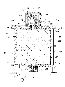
motor/generator 72 illustrated is
preferably a three-phase induction type unit, which is comprised of a rotor
74, press fit onto the coupling
shaft 34, and a stator winding 76, pressed into the inside circumference of
the cylindrical outer wall 25 of
the second housing 22.
[0074] As illustrated in Figures 1 through 4, the motor/generator 72 is
preferably liquid cooled, such
that the second housing 22 also preferably includes a coolant jacket comprised
of a main coolant channel
80 encircling the outer surface of the cylindrical outer wall 25 of the second
housing 22, said main coolant
channel 80 being enclosed on its outer periphery by a removable outer shell
88. 0-ring seals 81 assist in
sealing the removable outer shell 88 to the cylindrical outer wall 25 of the
second housing 22. Coolant
flows into ingress port 38, passes through the main coolant channel 80, and
then outward through egress
port 39. The coolant flow can be via an external pump, or natural convection
(in which case the ingress 38
and egress 39 ports are beneficially reversed from the arrangement shown) in
order to the remove waste
heat from the second housing 22 and the stator winding 76.
[0075] Electrical cable connections to the motor/generator 72 are
preferably made through the top
plate 35 at port 41, which port should be made vacuum tight around such
connections by rubber grommets,
0-ring seals and the like (not shown).
[0076] It will be appreciated that the rotor 25 is, as shown in the
Figures, solid and comprised of high
strength steel. At least a portion of the rotor 25 must be ferromagnetic in
order to interact with the
magnetic thrust bearing assembly 26. Preferably, at least an upper portion of
the rotor opposite the bearing
assembly 26 is magnetic, and, as a further preference, the entire rotor 25 is
ferromagnetic. It may
CA 02801307 2012-11-30
WO 2011/153612
PCT/CA2011/000641
21
preferable in some embodiments of the energy storage system 20 for the rotor
25 to have a mass between
about 1,000 kg and 5,000 kg with 3,000 kg a preferred mass.
[00771 In
operation, power is supplied to the rotor/generator 72 which applies a torque
to accelerate
the rotor 25. It is preferable, but not essential, that the motor/generator 72
be capable of rotating the rotor
25 at high speed, between about 10,000 and 20,000 RPM. As the rotor 25
accelerates, it stores the energy
supplied by the rotor/generator 72 as kinetic energy. Upon attainment of the
maximum speed, the
electrical power may be disconnected. In a typical implementation for the
maximum rotation speed of the
rotor 25 is obtained within 2 hours of the electrical connection to the
motor/generator 72 being energized
by the power grid. It also be preferable, but not essential, such high speed
rotation of the rotor 25 continue
for at least 6 hours following the electrical connection to the power grid
being de-energized. If the power
is disconnected, or if additional electrical energy is required by the grid,
the motor/generator is switched to
a generating mode and the energy stored in rotor 25 drives the generator and
supplies electrical power. In
some embodiments, the storage capacity of the energy storage system 20 is
approximately 20 kWh. The
energy storage is a function of the weight of the flywheel and the speed at
which the flywheel 24 is rotated.
During rotation the gap 30 is maintained by the bearing assembly 47a. Changes
in axial dimensions, due
to thermal changes or dynamic forces, is accommodated in the lower bearing 47b
which may slide axially
relative to the end plate 33. The flux path described in Figure 8 ensures the
rotor 25 is maintained axially
by the magnetic bearing and accordingly, the axial loads in the bearings 47a,
47b are reduced.
100781
Because of the relationship between an energy storage system's 20 energy
storage limitations
and an energy storage systems' 20 inherent size and weight, it may be
advantageous and preferable in
some applications to use, or otherwise require the use of, a plurality of
smaller energy storage systems 20
in favour of a lesser number of large energy storage system 20 constructed
according to the preferred
embodiment. An array of relatively smaller energy storage systems 20 allows
for users to store a greater
amount of energy in the form of kinetic energy whilst maintaining ease of
deployment and greater
flexibility to accommodate for electrical power requirements of different
scales in particular applications.
In such situations, it may be preferable that the array of energy storage
systems be controlled by a common
control unit. Further, it may be even more preferable that the common control
unit controls the electrical
CA 02801307 2012-11-30
WO 2011/153612
PCT/CA2011/000641
22
energy draw and the release of. energy from each of the energy storage systems
20 in the array of energy
storage systems. For some commercial embodiments, it may be preferable to have
an array of energy
storage systems having a collective energy output of at least 500 kWh.
[0079] In this regard, Figure 9 illustrates an array 100 of energy storage
systems 120, 220, 320, and
420 being contained within a collective container 101.
[0080] Figure 10 illustrates an array or a plurality of collective
containers 101, 201, 301, 401 each of
which contains an array of energy storage systems 120, 220, 320, etc.
[0081] Figure 11 illustrates an array of domed vaults 102, 202, 302, and
402. Each of the vaults is
above grade and houses an energy storage system 120 therewithin. Similarly,
Figure 12 illustrates in
section an array of concrete vaults 102, 202, 302, 402, and 502. Each of the
vaults 102, 202, 302, 402, and
502 may be located below-grade, and each houses an energy storage system 120,
220, 320, etc.,
respectively.
[0082] The provision of the flywheel support with one of the bearing
assemblies axially locating the
shaft and the other bearing permitting the drive shaft to float axially
facilitates alternative configurations of
rotor. As shown in figure 13, the rotor 25 is formed with ancillary rotor
discs, 125 spaced along the drive
shaft 24a,
[0083] Each of the discs 125 has an upper face 127 directed toward a
respective permanent magnet
thrust bearing 126 which is located within the housing 21. Upper bearing
assemblies 147 axially locate the
rotor 25 with a lower bearing assembly 147 radially permitting relative axial
movement.
[0084] The discs 125 are formed from a ferromagnetic material and the
thrust bearings 126 have a
similar configuration to the thrust bearing shown in figure 4, with an annular
permanent magnet and a
surrounding skirt overlapping the discs.
[0085] The magnetic thrust bearings attract respective ones of the discs
125 to support the mass of
the rotor 25, as described above.
CA 02801307 2012-11-30
WO 2011/153612
PCT/CA2011/000641
23
100861 It
will be appreciated that the array of discs 125 may be formed on the lower
drive shaft 24c to
support the rotor from beneath by attraction.
[0087]
Various other modifications and alterations may be used in the design and
manufacture of the
energy storage system according to the present invention without departing
from the spirit and scope of the
invention, which is limited only by the accompanying claims. For example,
separate and apart from the use
of the liquid cooling means illustrated in the Figures, the second housing 22
could additionally be
fabricated with external cooling fins for convective or forced air cooling to
the ambient atmosphere.