Note: Descriptions are shown in the official language in which they were submitted.
CA 02801445 2013-01-10
MAGNETIC FIELD DEVICE FOR MAPPING AND NAVIGATION IN
LAPAROSCOPIC SURGERY
BACKGROUND
1. Technical Field
[0002] The present disclosure relates generally to devices, systems, and
methods for
marking and locating points of interest during a surgical procedure, and more
particularly to a
magnetic field device for mapping and navigating during a minimally invasive
surgical
procedure.
2. Background of Related Art
[0003] Many surgical procedures necessitate determining the location of
surgical tools or
internal features within a patient's body. Often these devices and/or internal
features are not
readily locatable without costly and time consuming procedures. Various
imaging devices, e.g.,
MRI and/or x-ray, may be used to view the inside of a patient's body.
[0004] However, such devices may not be suitable during a surgical
procedure where the
location of such structures may have to be determined rapidly. In addition,
imaging devices that
utilize radiation may be detrimental to the health of a patient. Moreover, the
images taken by the
imaging devices, e.g., MR1 and/or x-ray, may have to be developed and analyzed
by specialized
technicians. In addition, such procedures are often costly. Often, once
particular areas are
identified, a surgeon will place a physical marker in that location, e.g.,
form an incision and
1
CA 02801445 2013-01-10
place a cannula at that location. It would be desirable to have less damaging
ways to mark and
label areas of interest in real-time.
[0005] Consequently, a continuing need exists for devices and methods that
can
accurately and rapidly locate instruments and structures within a patient's
body during the course
of a surgical procedure.
SUMMARY
[0006] The present disclosure relates to systems, devices, and methods for
use in a
minimally invasive surgical procedure to map the position of underlying
structures, e.g., body
structures or surgical devices and/or instruments.
[0007] A surgical mapping system for locating structures under body tissue
may include
one or more magnets, e.g., permanent magnets, that are configured to be
emplaced under tissue
within a body cavity. The methods may be emplaced with a grasper or
temporarily affixed
affixed to an implant, such as a hernia mesh, or affixed to tissue using
fastening methods such as
a suture, barbs, staples or other fasteners. Each magnet produces a magnetic
field having a
magnitude that is greater closer to the magnet than it is at farther distances
from the magnet. A
mapping device includes one or more sensors, each configured to detect the
magnitude of the
magnetic field and an indicator providing an indication of the magnitude of
the magnetic field at
a location. By sensing the magnitude of the magnetic field, the placement of
the magnets under
the tissue may be determined through trial and error by moving the mapping
device until receipt
of an appropriate indication by the indicator that the mapping device is
aligned with the
emplaced magnet.
[0008] The indicator may include one or more light sources, e.g., light
emitting diodes
(LEDs), that may increase in brightness as the mapping source gets closer to
the emplaced
CA 02801445 2013-01-10
magnets. The one or more light sources may also include a number of light
sources and may be
arranged in a row to provide a light indicator bar. As the mapping device is
positioned closer to
an magnet, a greater number of the light sources may become illuminated.
[0009] Once underlying magnets are located, their locations may be marked
electronically on monitoring systems or physically on the patient's skin. For
example, a marker
may be used to mark the locations on the skin at the locations where the
magnets are underneath.
The mapping device may include an aperture for the reception of the marker to
facilitate marking
the skin.
[00010] During use, points of interest or locations under the tissue and/or
within the body
cavity are marked by implanting magnets at those locations. The marked
locations are readily
found using the above described mapping devices. During use, the operator of
the mapping
device will move the mapping device along the surface of a patient's tissue,
e.g., the patient's
tissue, and will observe indications from the indicator as to the strength of
the magnetic fields in
the locations where the mapping device is moved. By trial and error, each of
the magnets will be
located by finding those locations where the magnetic field is strongest.
[0010] These and other embodiments of the present disclosure will be
described in
greater detail hereinbelow.
BRIEF DESCRIPTION OF THE DRAWINGS
[0011] Embodiments of the present disclosure are described herein with
reference to the
accompanying drawings, wherein:
[0012] Fig. 1 is a perspective view of a magnet;
[0013] Fig. 1A is a top view of a mapping device in accordance with the
present
disclosure;
3
CA 02801445 2013-01-10
[0014] Fig. 2 illustrates locating and marking the location of the
emplaced magnet of Fig.
1 by using the mapping device of Fig. 1A;
[0015] Fig. 3 illustrates the mapping device of Fig. 1 A placed on a
tissue surface and
aligned along a common axis with the magnet of Fig. 1 and a marking device;
[0016] Fig. 3A is a top view of markings on a tissue surface of a patient;
[0017] Fig. 3B illustrates deployment of a mesh at the location of the
magnet of Fig. 1;
[0018] Fig. 4 is a top view of another mapping device in accordance with
the present
disclosure; and
[0019] Fig. 5 illustrates the mapping device of Fig. 4 aligned with a
marker, and the
magnet of Fig. 1 on the underside of tissue.
DETAILED DESCRIPTION
[0020] Particular embodiments of the present disclosure will be described
herein with
reference to the accompanying drawings. In the figures and in the description
that follows, in
which like reference numerals identify similar or identical elements, the term
"proximal" will
refer to the end of the apparatus that is closest to the operator during use,
while the term "distal"
will refer to the end that is farthest from the operator during use.
[00211 Devices, systems, and methods for mapping the locations of internal
bodily
structures are described in detail below. The placement or implantation of
magnets, e.g.,
permanent magnets, at desired locations within the surgical site facilitates
later location of these
locations. Mapping internal structures is desirable in many procedures
including hernial repairs
(e.g., inguinal, ventral, and umbilical hernial repairs). During a hernial
repair, a mesh, e.g., a
woven material, is often emplaced to patch an area of weakness or to plug
holes. The mesh is
placed either under or over the defect in the abdominal wall and held in place
by sutures. In
4
CA 02801445 2013-01-10
essence, the mesh functions as "scaffolding" for new growth of a patient's own
tissue, which
eventually incorporates the mesh into the surrounding area.
[0022] A hernial mesh may fail because of inadequate overlap of the mesh
covering the
hernia defect or inaccurate placement of sutures holding the mesh in place.
Such failures may be
inhibited by facilitating accurate and precise placement of the mesh at the
areas of defect. It is
with this in mind that the devices, systems, and methods will be described
with reference to the
repair of a hernial defect. Currently, a surgeon may create a map for himself
by locating defects,
creating a hole in the defect, and placing a cannula through the defect. The
devices, systems, and
methods described in detail below minimize the need to create holes through
the defect itself by
providing another way to mark and map these locations.
[0023] It is to be understood that hernial repair is only an exemplary
use, and that the
devices, systems, and methods disclosed herein may be utilized during any
surgical procedure
where it is desirable to guide a surgeon to internal structures and/or
facilitate the creation of a
map that will help precisely guide the surgeon to targeted locations within
the surgical site.
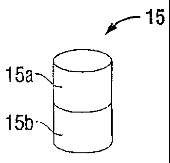
[0024] An implantable magnet 15 (Fig. 1) may be placed underneath a tissue
surface "T",
e.g., abdominal wall (Figs. 2 and 3B) within a body cavity "C", e.g.,
abdominal cavity. As
shown in Fig. 1, the magnet 15 may be a permanent magnet including a first
pole 15a and a
second pole 15b that are commonly referred to as "north" and "south" poles.
Although magnet
15 may be substituted by other devices that emit a magnetic field, a permanent
magnet such as
magnet 15 is relatively inexpensive, requires no batteries, and requires
little or no maintenance.
The magnet 15 emits a magnetic field that can be measured in the international
unit of magnetic
flux density called "Tesla" ("T"). The magnetic field, Baxis (measured in
tesla) of an ideal dipole
measured along its axis is calculated as follows: Baxis = {0-10)/(4701 x
[(2)/d3], where go is the
CA 02801445 2013-01-10
permeability constant (47cx10-7 T m/A), d is the distance from the center of
the dipole in meters,
and 11 is the magnetic moment. The magnetic moment p. measures the strength of
the magnet.
As seen from this equation, the strength of the magnetic field is distance
dependant. The
magnetic field strength will weaken rapidly when moved a short distance away
from the magnet,
and will change relatively slowly at distances farther away from the magnet.
[0025] As shown in Fig. 2, magnet 15 is emplaced on the underside of
tissue "S".
During a hernial repair, for example, the location where the magnet 15 is
placed may be an area
that has been identified as having a defect. An instrument 80 that is
configured and adapted for
use during a minimally invasive surgical procedure and including an end
effector that is capable
of grasping the magnet 15 may be used to implant the magnet 15 at a desired
location, e.g., a
hernial defect. Once the magnet 15 is emplaced it may serve as a beacon by
sending signals, i.e.,
emitting a magnetic field, to a suitable device that can detect and locate the
magnet 15, thereby
facilitating the relatively rapid relocation of the point of interest.
[0026] Mapping devices 100, 200 (Figs. 1A and 4) that are configured to
detect the
magnet 15 and guide a surgeon to its location are described hereinbelow. As
shown in Fig. 1A, a
mapping device 100 includes a magnetic field sensor 102, a first indicator 104
and/or a second
indicator 110, a threshold button 108, and a power source 106. The mapping
device 100 is
configured and adapted to locate implants that emit a magnetic field by
detecting the strength of
the magnetic field emitted by the implant, e.g., a magnet. The mapping device
100 is configured
and adapted to provide indication to a user when the mapping device 100 is
being moved toward
or away from the implant.
[0027] The magnetic field sensor 102 measures the magnetic field strength.
Suitable
magnetic field sensors 102 include, but are not limited to, Hall sensors
and/or magnetoresistive
6
CA 02801445 2013-01-10
sensors. The first indicator 104 may be a single light, e.g., a light emitting
diode (LED). The
second indicator 110 may be a light bar including a plurality of lights, e.g.,
an array of LEDs. As
the magnetic field strength changes as the distance between the field sensor
102 and the magnet
15 changes, the brightness of the LEDs may change, e.g., brighter when in
close proximity and
dimmer when distant, and/or the number of LEDs illuminated may change, e.g., a
stronger
magnetic field corresponds to a greater number of illuminated LEDs and a
weaker magnetic field
corresponds to a lesser number of illuminated LEDs.
[0028] As
discussed above, the magnetic field strength of a permanent magnet changes
with respect to distance in an inverse cubed relation. This means that the
magnetic field strength
changes rapidly as the field sensor 102 and the magnet 15 approach one
another. Therefore, it
may be convenient to implement an autoscale feature. An exemplary processing
algorithm will
now be described. However, it is to be understood that other processing
procedures may be
used. For example, at power up, the field sensor 102 reads the magnetic field
at a given location.
The level of residual magnetic field, which varies by the environment, is
determined by
calculating an average. The difference of current field measurement and the
initial level is
represented by the first and/or second indicators 104, 110. As the brightness
and/or bar length
(number of illuminated lights) approaches the maximum level, the scale is
automatically
changed, e.g., to 20% of sensitivity, from the previous value. The sensitivity
of the field sensor
102 may be auto-adjusted. For example, at the start of the procedure, the
sensitivity is high
enough to detect a small permanent magnet at distances such as 10 centimeters,
and at the final
stage, the magnet can be as close as 1 centimeter (field increases for several
orders of magnitude)
but still provide non-saturated indication because scale is automatically
adjusted to a level when
a stronger field can be detected. Also, as shown in Fig. 1A, the mapping
device 100 may include
7
CA 02801445 2013-01-10
a threshold button 108 which may be used to set the current field level at the
zero level. After
activating the threshold button 108, only magnetic fields having a greater
value will be
displayed. The threshold button 108 may also be used to reset the indicator
scales of the first
and/or second indicators 104, 110 back to their original level of sensitivity.
[0029] A processing unit 116 may execute the above described algorithm and
control the
provided indication. The processing unit 116 may include any type of computing
device,
computational circuit, or any type of process or processing circuit capable of
executing a series
of instructions that are stored in memory. The processing unit 116 may include
multiple
processors and/or multicore CPUs and may include any type of processor, such
as a
microprocessor, digital signal processor, microcontroller, or the like. A
power source 106 may
include an internal battery to power the mapping device 100.
[0030] During use, as shown in Figs. 2 and 3, the mapping device 100 is
moved along a
surface of tissue "S", e.g., a patient's abdomen. Through trial and
observation, the mapping
device 100 is moved along the surface of the tissue "S" until the highest
strength magnetic field
is observed and indicated by the first and/or second indicators 104, 110,
thereby notifying the
user that the magnet 15 and the mapping device 100 are at closet proximity. A
proximal end 101
of the mapping device 100 may be generally pointed to facilitate marking of
the tissue "S" at a
particular location.
[0031] In embodiments, a mapping device may include one or more sensors
that can
detect the magnetic field at more than one location or along more than one
axis. The mapping
device 200, as illustrated in Fig. 4, includes four sensors 202a-d that are
evenly spaced at the
same distance from the center of an aperture 210. A power source 206 may
include an internal
battery to power the mapping device 200. In addition, the algorithms employed
in controlling
8
CA 02801445 2013-01-10
when the various indications are provided are controlled by a processing unit
216 that may
include any type of computing device, computational circuit, or any type of
processor or
processing circuit capable of executing a series of instructions that are
stored in a memory. The
processing unit 216 may include multiple processors and/or multicore CPUs and
may include
any type of processor, such as a microprocessor, digital processor,
microcontroller, or the like.
[0032] The
mapping device 200 may include a strength indicator 212, e.g., a light (e.g.,
LED) of variable intensity, and one or more directional indicators 204a-d to
provide guidance as
to the source of the magnetic field. For example, four directional indicators
204a-d can
directional guidance to move the mapping device 200 in a particular direction
along the tissue
"S" to bring the mapping device 200 closer to the emplaced magnet 15. As shown
in Fig. 4, a
first directional indicator 204c may be illuminated to instruct a user to move
the mapping device
200 in an upward direction; a second directional indicator 204a may be
illuminated to instruct a
user to move the mapping device 200 in a downward direction; a third
directional indicator 204d
may be illuminated to instruct a user to move the mapping device 200 in a
leftward direction;
and a fourth directional indicator 204b may be illuminated to instruct a user
to move the mapping
device 200 in a rightward direction. A user may be instructed to move in more
than one of these
directions at the same time. For example, the first and second directional
indicators 204c, 204b
may be illuminated at the same time to instruct the user to move the mapping
device in both an
upward and rightward direction. Once the magnet 15 is located within the
boundaries of aperture
210, an indication is provided, e.g., all of the indicators 204a-d, 212 are
illuminated. The
aperture 210 defines a space that facilitates marking the surface of the
tissue "S" by placing a
mark within the aperture 210. For example, a permanent ink marker may be used
to place marks
on the surface of the tissue "S". As the start of the procedure (as with the
threshold button 108
9
CA 02801445 2013-01-10
of the mapping device 100), environmental magnetic field disturbance is
minimized by
depressing threshold button 208 such that a baseline magnetic field detected
will not cause an
indication to be provided.
[0033] The direction to the magnet 15 can be calculated using differential
sensor reading
in two orthogonal axes, e.g., 2-dimensional Cartesian coordinates x
("horizontal") and y
("vertical"). 3-dimensional coordinates may be determined by also reading the
magnetic
strength along a third dimension, z, thereby also determining the depth of the
location of magnet
15. As discussed above, four sensors 202a-d surround central aperture 210.
Each sensor 202a-d
provides reading of the magnetic field strength at its location such that
direction to the magnet 15
can be calculated using differential sensor reading in two orthogonal axes. It
is contemplated
that a different number of sensors may be utilized even though for simplicity,
mapping device
200 is shown and described as having four sensors 202a-d (i.e., two for the
horizontal axis and
two for the vertical axis). An algorithm is implemented in the processing unit
216 to illuminate
appropriate directional indicators 204a-d and vary the intensity of the
magnetic strength indicator
212. In an embodiment of a suitable algorithm, once one or more directional
indicators 204a-d
are lit, the mapping device 200 should be moved in the direction of the lit
directional indicator
204a-d until both directional indicators 204a-d on the appropriate axis are
lit. This procedure is
repeated until all of the directional indicators 204a-d are lit. Unlike the
mapping device 100, the
mapping device is less sensitive to distance to the magnet 15 because it
utilizes a differential
reading from the sensors 202a-d as opposed to an absolute value.
[0034] The algorithm for mapping device 200 may be described as follows.
At start up,
reading of the sensors 202a-d are taken far from magnet 15 and are averaged to
find zero level.
When the mapping device 200 approaches magnet 15, the field becomes stronger,
and the
CA 02801445 2013-01-10
differential value of two of the sensors 202a-d, i.e., a pair of sensors 202a-
d for each of the
horizontal and vertical axes, is calculated. If such differential value
exceeds a certain delta
value, a directional indicator 204a-d is lit up, while the directional
indicator 204a-d that indicates
an opposite value is set to off. If both values are above a certain threshold
level, but below delta
both lights are set to on. The delta value is dependent on average field
strength; it is
automatically set to a fraction of the averaged magnetic field measured by all
of the sensors
202a-d. This is done to compensate field gradient at different distances. At
short distances from
the magnet 15, the magnetic field detected is much stronger and is less
uniform, and the delta is
set to a higher value as compared to a situation in which the magnetic field
is weak and more
uniform, and the difference between the sensor readings is minimal. The
algorithm may also
implement low-pass digital filters, calibration of the sensors, noise
suppression, and a manual
recalibration procedure.
[0035] During use, magnets 15 are emplaced at desired locations, e.g., at
the locations of
hernial defects, and one of the mapping devices 100, 200 is used to detect the
location of the
magnets under the tissue "S". As shown in Fig. 3A, markings "M" and placed on
the surface of
the tissue "S", and dimensions d between markings representing the locations
or points of
interest are calculated. As shown in Figs. 2 and 3, a marking device 2 is used
to place marks on
the surface of the tissue "S" at the locations of the magnets 15. In so doing,
the surgeon is
provided with a landscape map on the surface of the tissue "S". The markings
"M" help the
surgeon accurately place a device, e.g., a mesh 27, at the locations or points
of interest marked
by the markings "M".
[0036] It will be understood by those skilled in the art that various
modifications and
changes in form and detail may be made to the present disclosure without
departing from the
11
CA 02801445 2013-01-10
scope and spirit of the same. Therefore, the above description should not be
construed as
limiting, but merely as exemplifications of particular embodiments. While
several embodiments
of the disclosure have been shown in the drawings, it is not intended that the
disclosure be
limited thereto. Rather, the disclosure is intended to be read as broadly in
scope as the art will
allow.
12