Note: Descriptions are shown in the official language in which they were submitted.
CA 02801506 2013-01-09
TITLE
Chain Guide For A Roller Blind Or Roller Shade
FIELD
This invention relates generally to roller blinds, shades and other similar
types
of window coverings, and in particular to a new chain guide for a roller blind
or
roller shade of the type driven by a clutch that is actuated through applying
a
tensile load to a chain, rope or cable that engages the clutch.
BACKGROUND
Most roller blinds or roller shades are constructed with a clutch mechanism
that
allows the blind fabric or material to be raised or lowered in front of a
window
pane as desired in order to block the infusion of light into a room or
building.
In many instances the clutch is activated through the use of a chain, rope or
cable that is looped around the clutch, such that pulling on one end of the
chain
or rope causes the clutch to retract the fabric, whereas pulling on the
opposite
end of the chain or rope causes the clutch to lower the fabric in front of the
window pane. Often the chains that are utilized in roller blinds are ball
chains.
Ball chains present a desirable aesthetic appearance and also allow the
exterior
1
CA 02801506 2013-01-09
surface of the clutch to be formed with concave depressions that readily
accept
the exterior surface of the individual balls on the chain, presenting a drive
mechanism that minimizes slippage between the chain and the clutch. In some
cases the ball chains are metal while in other cases the chains are a
"hybrid",
formed through the attachment of metallic or composite balls onto the exterior
surface of a rope or cable. In either instance the functionality of the ball
chain
and the clutch is essentially identical.
While ball chains have been successfully used to operate the clutch of a
roller
blind or roller shade for a considerable length of time, they suffer from the
inherent limitation of being noisy during operation. The exterior surfaces of
the
balls (whether they be metal, plastic or a composite material) tend to be
relatively hard such that as they come into contact with components of the
blind, mechanical noise is generated. For example, when one end of a chain
attached to the clutch of a roller blind is pulled in order to either raise or
lower
the blind, if the chain is not pulled in a precise vertical angle the balls
may
come into contact with structural and/or aesthetic or trim components of the
blind, causing a "ratcheting" sound to be generated. Further, when a blind is
opened or closed an individual will typically grasp one side of a chain that
is
looped around the clutch and hanging vertically downward from the blind. The
side of the chain that is grasped is held in tension, whereas the opposite
side of
the chain loop is typically allowed to hang free. As the chain is pulled the
free
2
CA 02801506 2013-01-09
side of the loop will sometimes contact components within the end of the
roller
blind, once again causing the generation of mechanical noise.
In order to minimize the noise created through such contact, others have
attempted to coat various components of the blind's hardware with a soft and
somewhat pliable plastic or similar material that has less of a tendency to
create mechanical noise. Although such action results in a reduction in the
level of noise generated to some degree, the soft material tends to wear
quickly
on account of friction between it and the exterior surface of the chain.
SUMMARY
The invention therefore provides a chain guide for a roller blind or roller
shade
that addresses some of the deficiencies in the art.
In one of its aspects the invention provides a chain guide for a roller blind
or
roller shade of the type driven by a clutch that is activated through applying
a
tensile load to one end of a chain, rope or cable that engages the clutch, the
chain guide comprising two or more rollers mounted to one or more structural
members positioned about the end of the blind, said rollers engaging the
chain,
rope or cable and directing the chain, rope or cable onto the clutch, said
rollers
helping to maintain the position of the chain, rope or cable adjacent the
clutch
and helping to eliminate contact between the chain, rope or cable and the
3
CA 02801506 2013-01-09
structural members of the blind thereby reducing the mechanical noise
generated by the chain, rope or cable during operation of the blind.
Further aspects of the invention will become apparent from the following
description taken together with the accompanying drawings.
BRIEF DESCRIPTION OF THE DRAWINGS
For a better understanding of the present invention, and to show more clearly
how it may be carried into effect, reference will now be made, by way of
example, to the accompanying drawings which show exemplary embodiments
of the present invention in which:
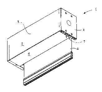
Figure 1 is a lower side perspective view of a typical roller blind or roller
shade
that is actuated by a ball chain and that utilizes the chain guide in
accordance
with an exemplified embodiment of the present invention.
Figure 2 is a lower perspective view of the roller shade of Figure 1 having
its
bottom and rear trim plates removed.
Figure 3 is an end view of the roller blind shown in Figure 1 having its
exterior
trim plate removed.
4
CA 02801506 2013-01-09
Figure 4 is an exploded perspective view of the end of the roller blind shown
in
Figure 3 having its roller and roller tube removed.
Figure 5a is a bottom non-exploded view of the end of the roller blind shown
in
Figure 4.
Figure 5b is an enlarged detail view of portion A of Figure 5a.
Figure 6a is an upper side perspective view of the roller hub shown in Figure
4.
Figure 6b is a side elevation& view of the roller hub shown in Figure 4.
Figure 7a is an upper side perspective view of the roller sleeve shown in
Figure
4.
Figure 7b is a side elevational view of the roller sleeve shown in Figure 7a.
Figure 8 is an upper side perspective view of an alternate embodiment of the
roller hubs and sleeves in accordance with the present invention.
5
CA 02801506 2013-01-09
DESCRIPTION
The present invention may be embodied in a number of different forms. The
specification and drawings that follow describe and disclose some of the
specific
forms of the invention.
In the attached drawings there is shown a typical roller blind or roller shade
designated generally by reference numeral 1. It will be appreciated that much
of the particular form and structure of the roller blind is of little
consequence in
the present invention. However, for illustration purposes the blind shown in
the
attached figures is comprised generally of a pair of end plates or brackets 2,
a
head box enclosure 3 (formed generally from a bottom plate 4 and a rear plate
5), blind fabric 6 and a chain 7. The blind fabric 6 is received about a
roller
tube 8, which is in turn connected to and driven by a clutch 9. As is shown
more specifically in Figures 3 and 4, chain 7 is looped about a portion of the
exterior surface of clutch 9 such that pulling on one end of the chain causes
the
clutch to rotate in one direction, whereas pulling on the opposite end of the
chain causes the clutch to rotate in the opposite direction. Thus, pulling or
applying a tensile force to the chain will cause the blind fabric to be raised
or
lowered, depending upon which portion of the chain loop is grasped.
6
CA 02801506 2013-01-09
In accordance with the invention there is provided two or more rollers 10 that
are mounted to one or more structural members in end brackets 2. Rollers 10
engage the chain and assist in directing the chain onto the clutch to thereby
help maintain the positioning of the chain adjacent to the clutch and to help
eliminate contact between the chain and the structural members of end
brackets 2, and roller blind 1 in general. In the attached drawings two
rollers
are utilized, however, it will be appreciated that in other instances it may
be
desirable to use more than two rollers to help maintain the positioning of the
chain.
With specific reference to Figures 3 and 4, in one embodiment of the invention
rollers 10 are mounted on a pair of fixed shafts 11, that are in turn mounted
on
end bracket 2. In this embodiment, the rollers are comprised generally of a
roller hub 12 that is received over shaft 11 and that is free to rotate
relative
thereto. Securing hub 12 to shaft 11 can be accomplished in a variety of
different ways using a wide variety of different fasteners and fastening
means.
In the particular embodiment shown in the attached drawings, the outer ends of
the shafts have an enlarged circumferential rib or lip 13 that exceeds the
internal diameter of hub 12. The hub contains a slit 14 along its lateral axis
that allows the hub to be expanded slightly, thereby increasing its internal
7
CA 02801506 2013-01-09
diameter to allow it to be pushed over the end of shaft 11. With the hub
located over the shaft releasing the hub causes it to return to its original
configuration such that its internal diameter is less than that of rib 13, but
still
slightly larger than that of shaft 11. In this manner the hub will be retained
securely upon the shaft but free to rotate thereabout.
In order to assist rollers 10 in accepting the exterior surface of chain 7, in
one
preferred embodiment of the invention the exterior surface of the rollers is
concave with an outer dimension that approximates the outer dimension of the
chain. With the concavity of the exterior surface of the rollers approximating
the diameter of the chain there exists a tendency for the rollers to maintain
contact with the chain as it is operated, thereby reducing the likelihood of
contact between the chain and other structural components of the blind.
Each of the rollers 10 may include an exterior sleeve 15 formed from a pliable
relatively soft flexibly resilient material. It is expected that in most
instances
the sleeves will be formed from a rubber, silicone or similar type of material
that can be stretched over and received about the exterior surface of hub 12.
In that regard, sleeves 15 may also be formed with a concave exterior surface,
similar to that of the hub. The sleeves may also be of a size results in the
application of an external compressive force to the hub in order to maintain
slit
14 in a closed configuration and to assist in keeping the hub from
accidentally
8
CA 02801506 2013-01-09
being ejected over rib 13 on shaft 11. The relatively soft and resilient
nature of
the material from which sleeve 15 is formed will further serve the function of
helping to prevent slippage between the rollers and the chain, and will reduce
the likelihood of mechanical noise being generated through the operation of
the
blind.
In the construction of a roller blind, the size of the clutch and the roller
tube are
often a function of the length of blind fabric that is to be received and
wound
about the tube. To minimize the number of different component parts required
to assemble blinds of different sizes and configurations, manufactures often
attempt to utilize common end brackets for blinds of different clutch and/or
roller tube dimensions. For that reason, the end brackets 2 of the roller
blind
may include means to permit shafts 11 to be positioned at different locations
on
the end brackets. Altering the location of the positioning of the shafts upon
the
end brackets allows the end brackets to accommodate clutches of different size
diameters, while still enabling the rollers 10 to direct the chain properly
onto
the exterior surface of the clutch and to minimize contact of the chain with
the
structural components of the blind. In the embodiment of the invention shown
in Figures 3 and 4, end brackets 2 contain additional holes 16 through which
fasteners can be received in order to position shafts 11 at alternate
locations
within the end brackets.
9
CA 02801506 2013-01-09
Figure 8 shows yet a further embodiment of the invention where shafts 11 are
received upon a plate 17 that can then be secured at a desired location within
the end bracket. In this manner the manufacturer or installer has the option
of
incorporating the rollers into the end bracket construction were desired, or
eliminating them where it is deemed that they may not be necessary. Further,
the manufacturer and installer are presented with the flexibility of
positioning
plate 17 within the end bracket at its optimal location and not limited to pre-
set
positions of holes 16. The incorporation of shafts 11 and rollers 10 upon
plate
17 also allows the rollers to be retrofitted into existing blinds without
having to
replace the end brackets or other components of the blind. It is noted that in
Figure 8 plate 17 is shown with three shafts mounted thereto, however, it will
be appreciated that the plate could also be configured with two or more
shafts.
The employment of the above-described invention will thus present a
mechanism that will help to maintain the positioning of the chain in a roller
blind with respect to the location of the blind's clutch and structural
components
to help eliminate contact between the chain and other components and to
reduce mechanical noise. The invention also helps to prevent contact between
the chain and structural components which can result in frictional wear and a
general deterioration of the blind components.
CA 02801506 2013-01-09
It will be appreciated that what have been described are the preferred
embodiments of the invention. It will also be appreciated that alterations to
the
embodiments could be made. For example, although the clutch depicted in the
attached drawings and described above is operated by a ball chain, the clutch
could equally be operated by a rope, cable or other form of chain. The scope
of
the claims should not be limited by the preferred embodiments set forth in the
examples described, but should be given the broadest interpretation consistent
with the description as a whole.
11