Note: Descriptions are shown in the official language in which they were submitted.
CA 02801711 2012-12-05
WO 2011/163197 PCT/US2011/041207
DISPENSING PACKAGES FOR MEDICAL DEVICES HAVING TWO COMPONENTS
THAT ARE MECHANICALLY INTERLOCKED AND METHODS THEREFOR
BACKGROUND OF THE INVENTION
Field of the Invention
[0001] The present invention generally relates to medical devices, and more
specifically
relates to packages for medical devices.
Description of the Related Art
[0002] Medical devices are typically stored in sterile packages prior to
being removed from
the packages for use during surgical procedures. For example, U.S. Patent No.
7,600,634 to
Malinowski et al. discloses a package for sutures including an envelope, an
outer jacket, and an
inner retainer that is secured within the outer jacket. The envelope receives
the outer jacket
and the inner retainer when the outer jacket and the inner retainer are
folded. The envelope
has a top sheet formed of a clear plastic, such as a polyethylene, and a
bottom sheet
constructed from paperboard, fiberboard, Tyvek , aluminum foil or other
similar materials. The
combination of materials of the top and bottom sheets prevents or impedes the
transmission of
moisture therethrough. The top sheet and the bottom sheet are generally
rectangular in shape,
are substantially the same size, and are adhered together along their
respective peripheries by
an adhesive material.
[0003] Commonly assigned U.S. Patent No. 6,533,112 to Warnecke discloses
packaging for
surgical sutures having a base with a raised edge and a spiral-like thread
duct that opens at a
first end thereof to a thread removal zone defined by a recess in the base
located adjacent the
first end of the thread duct. The base includes a thread tray positioned on an
opposite side of
the recess from the first end of the thread duct, and a thread holder having a
nose extending
inwardly from the raised edge of the base above the thread tray. The packaging
includes a
cover applied to the base above the thread duct. In one embodiment, the cover
is made from a
piece of cardboard that is coated on its underside with polyethylene. The
cardboard cover is
suitable for imprinting so that packaging can be easily provided with a
product label. In addition,
the cardboard cover is adapted to absorb residual quantities of water after a
package with
surgical suture material has been introduced into an outer wrapper. The
cardboard cover also
1
CA 02801711 2012-12-05
WO 2011/163197 PCT/US2011/041207
protects the surgical suture material and acts as a lid for the base to
reinforce the entire
package.
[0004] U.S. Patent No. 5,699,909 to Foster discloses a surgical instrument
package
including an outer envelope having first and second sheets of microorganism-
impervious
material that are bonded together around the periphery of each sheet, and a
retainer member
insertable within the outer envelope for holding a medical product. The
retainer member
includes a strip of flexible material such as polyethylene terephthalate,
polyethylene, vinyl,
polypropylene and ethylene vinyl acetate.
[0005] In spite of the above advances, there remains a need for a package
for medical
devices, such as tissue supporting implants, which has enhanced integrity and
functionality so
that surgical personnel may easily remove and control the medical device as it
is removed from
the package. There also remains a need for a package for dispensing medical
devices that
securely locks so that the medical devices do not easily spill out of the
packaging when the
package is opened. In addition, there is a need for medical packaging which
does not require
additional adhesive to secure the packaging and the medical products, thereby
reducing the bio-
burden and the possibility of adhesive leaching into the medical device. There
also remains a
need for a medical package dispenser whereby a medical device can be inserted
into the
package during a folding and/or tucking operation, which allows for easy
filling of the package
without risking folds or bends in the medical device and without risking the
medical device
catching a surface of the dispenser package during removal of the medical
device from the
package. There also remains a need for medical packaging that prevents
unwanted drops or
mishandling, and that allows for easy access and dispensing of the medical
product. There also
remains a need for medical packaging whereby the product is covered and
protected in a sterile
environment until immediately prior to use.
[0006] Packages for smaller format medical devices are often made entirely
of paperboard.
Large format packages, however, require an amount of paperboard that is too
great for practical
use with products requiring a drying cycle. Thus, there is also a need for
packaging utilizing a
sufficient amount of paperboard that is supplemented with a second material
that is less
hydrophilic. There also remains a need for packaging that is easy to open so
that the medical
2
CA 02801711 2012-12-05
WO 2011/163197 PCT/US2011/041207
device stored therein may be easily accessed. Providing a package having this
feature is
especially challenging where the non-paperboard component is not as
structurally supportive as
the paperboard component.
SUMMARY OF THE INVENTION
[0007] In one embodiment, a package for a medical device preferably
includes an outer
component, and an inner component mechanically interlocked with the outer
component. The
inner component is preferably adapted to be disposed inside the outer
component when the
package is closed. In one embodiment, the package is adapted to be opened
while the outer
and inner components remain mechanically interlocked together.
[0008] In one embodiment, the inner component is desirably stiffer than the
outer
component. The inner component is preferably more hydrophilic than the outer
component. In
one embodiment, the outer component is hydrophobic. In one embodiment, the
outer
component is porous. In one embodiment, the outer component preferably
includes a synthetic
material, such as Tyvek0, and the inner component includes cellulose material,
such as paper
or paperboard. Using Tyvek for the outer component makes the package highly
suitable and
compatible with ethylene oxide (ETO) sterilization processes.
[0009] In one embodiment, one of the outer and inner components desirably
includes at
least one slit and the other one of the outer and inner components desirably
includes at least
one tab for mechanically interlocking the outer and inner components together.
In one
embodiment, the inner component includes a pair of side tabs and the outer
component
includes slits for receiving the side tabs of the inner component.
[0010] In one embodiment, the outer component preferably has a first panel,
a second
panel adapted to fold over the first panel for closing the package, a first
locking slit extending
along a first side of the second panel, and a second locking slit extending
along a second side
of the second panel. The outer component desirably includes a first foldable
tab projecting from
a first side of the first panel, and a second foldable tab projecting from a
second side of the first
panel, whereby the first and second locking slits on the second panel are
desirably aligned with
3
CA 02801711 2012-12-05
WO 2011/163197 PCT/US2011/041207
the first and second foldable tabs on the first panel when the second panel is
folded over the
first panel.
[0011] In one embodiment, the inner component preferably has a first
locking tab projecting
from a first side of the inner component adapted to mechanically interlock
with the first foldable
tab of the outer component, and a second locking tab projecting from a second
side of the inner
component adapted to mechanically interlock with the second foldable tab of
the outer
component. In one embodiment, when the second panel of the outer component is
folded over
the first panel of the outer component, the first side locking tab is
insertable into the first locking
slit on the second panel for closing a first side of the package and the
second locking tab is
insertable into the second locking slit on the second panel for closing a
second side of the
package. In one embodiment, the first foldable tab preferably includes a slit
adapted to receive
the first side locking tab and the second foldable tab preferably includes a
slit adapted to receive
the second side locking tab.
[0012] In one embodiment, the locking tabs on the inner component thread
through the slits
in the foldable tabs of the outer component for interlocking the inner and
outer components
together. After the locking tabs have been threaded through the slits of the
foldable tabs, the
interlocked components (i.e. the locking tabs threaded through the slits of
the foldable tabs) are
preferably folded together, over the respective sides of the package for
closing the sides of the
package. The locking tabs of the folded, interlocked components may be
inserted into locking
slits on the outer component for locking the sides of the package.
[0013] In one embodiment, each of the first and second locking tabs
includes a rounded
lower end and an upper end including a locking recess and a gap toothed tab
adjacent the
locking recess. The locking recess on each of the first and second lateral
locking tabs is
preferably oriented toward an opening end of the package. In one embodiment,
each of the first
and second lateral locking tabs define a first length extending from the
rounded lower end to the
gap toothed tab thereof and each of the slits on the first and second foldable
tabs define a
second length, whereby the first length is greater than the second length.
[0014] In one embodiment, the first panel of the outer component desirably
has a lower end
and an upper end with a first upper end locking tab, and the second panel of
the outer
4
CA 02801711 2012-12-05
WO 2011/163197 PCT/US2011/041207
component desirably has a lower end and an upper end with a second upper end
locking tab.
In one embodiment, the lower ends of the first and second panels are
preferably connected
together along a score line that enables the second panel to be folded over
the first panel
whereupon the upper ends of the first and second panels are in substantial
alignment with one
another. In one embodiment, when the second panel is folded over the first
panel, the first
upper end locking tab of the first panel is desirably engageable with the
upper end of the second
panel and the second upper end locking tab of the second panel is desirably
engageable with
the upper end of the first panel for closing an upper end of the package.
[0015] In one embodiment, the first upper end locking tab preferably
includes a first flexible
flap adapted to engage the upper end of the second panel and the second upper
end locking
tab preferably includes a second flexible flap adapted to engage the upper end
of the first panel
for holding the upper end of the package closed.
[0016] In one embodiment, the first side locking tab desirably has a first
side with a rounded
surface for facilitating insertion of the first side locking tab into the
first locking slit on the second
panel and a second side with a locking recess adapted to retain the first side
locking tab in the
first locking slit on the second panel after being inserted into the first
locking slit. The second
side locking tab may have a first side with a rounded surface for facilitating
insertion of the
second side locking tab into the second locking slit on the second panel and a
second side with
a locking recess adapted to retain the second side locking tab in the second
locking slit on the
second panel after being inserted into the second locking slit.
[0017] In one embodiment, the inner component preferably includes a main
panel having an
upper end and a lower and at least one set of opposing securing elements
adapted to
releasably secure a medical device to the inner component. In one embodiment,
the opposing
securing elements are oriented toward the upper end of the main panel for
urging release of the
medical device from the upper end of the main panel.
[0018] In one embodiment, the inner component desirably includes a flexible
cover hingedly
secured to the lower end of the main panel that is adapted to fold over the
main panel for at
least partially covering a major face of the inner component. The flexible
cover may cover an
implant held by the inner component.
CA 02801711 2012-12-05
WO 2011/163197 PCT/US2011/041207
[0019] In one embodiment, at least one of the first and second panels of
the outer
component preferably includes a window for providing visual access inside the
package when
the package is closed.
[0020] In one embodiment, a package for a flat medical implant preferably
includes a
flexible outer component including a first panel and a second panel foldable
over the first panel
for closing the package, an inner component mechanically interlocked with the
flexible outer
component, and a flat medical implant held by the inner component. The upper
ends of the first
and second panels are desirably peelable away from one another while the outer
and inner
components remains mechanically interconnected together for opening the
package and
accessing the flat medical implant at an upper end of the package.
[0021] In one embodiment, the flat medical implant preferably includes a
laminate having a
surgical mesh and at least one absorbable layer overlying the surgical mesh.
The inner
component is desirably adapted to remove moisture present in the medical
implant and inside
the package.
[0022] In one embodiment, the medical device or flat medical implant
preferably has a
length of about 5-60cm and a width of about 10-30cm. The flat implant may have
an oval,
circular, square or rectangular shape. In one embodiment, the weight ratio of
the inner
component to the at least one absorbable layer of the flat medical implant is
between about
3.9:1 ¨ 5.5:1. In one embodiment, the weight of the absorbable part of a small
implant is about
1.17 grams and the weight of the inner component of the package is about 5.4
grams for a
weight ratio of about 4.6:1. In one embodiment, the weight of the absorbable
part of a medium
implant is about 2.34 grams and the weight of the inner component of the
package is about 12.8
grams for a weight ratio of about 5.5:1. In one embodiment, the weight of the
absorbable part of
a large implant is about 4.1 grams and the weight of the inner component of
the package is
about 20.7 grams for a weight ratio of about 5.1:1. In one embodiment, the
weight of the
absorbable part of an extra large implant is about 5.86 grams and the weight
of the inner
component of the package is about 23.1 grams for a weight ratio of about
3.9:1.
[0023] In one embodiment, a bi-component dispensing package for medical
devices
desirably includes an inner component having a first stiffness and at least
two locking tabs. The
6
CA 02801711 2012-12-05
WO 2011/163197 PCT/US2011/041207
two locking tabs preferably have a locking recess on one side and a rounded
edge on an
opposing side. The bi-component dispensing package preferably includes an
outer component
having a second stiffness that is less than the first stiffness. The outer
component preferably
has locking slots, whereby the locking tabs of the inner component are
mechanically interlocked
with the slots of the outer component with a locking recess on the locking
tabs being in close
proximity to an opening in the folder. In one embodiment, one component of the
bi-component
dispensing folder is flexible with respect to the other component and has
lower relative
hydrophilicity relative to the other component. In one embodiment, the inner
component may be
a cellulose material such as paperboard and the outer component may be a
synthetic material
such as Tyvek0.
[0024] In
one embodiment, locking tabs on the sides of the inner component preferably
lock
with slots in the outer component (i.e., a Tyvek0 folder) to form an
integrated dispensing
package or folder. The paper inner component in combination with the Tyvek0
outer
component work together to provide a secure package locking mechanism. In
one
embodiment, the paper insert is preferably placed on the inside of the folder
and desirably has
tabs that extend via slits or slots in the Tyvek0 folder outside of the Tyvek
folder. The Tyvek0
folder also has side tab extensions. These tabbed features are then wrapped
around the paper
insert as the paper insert is folded along designated score lines. The folder
is finished and
locked by having the paper tabs lock into place within locking slits on a
panel of the Tyvek0
folder.
[0025] In
one embodiment, the package is easily opened for dispensing the medical device
by unlocking two upper end locking tabs and folding or peeling away the two
upper ends of the
Tyvek0 folder. After the two upper ends of the Tyvek0 folder have been peeled
away, the
medical device, supported by the inner paper component, preferably projects
from the upper
end of the package for dispensing the flat medical device in the sterile
field. The Tyvek0
component of the dispenser package provides breathability, and the paper
component desirably
provides rigidity and serves a desiccant to remove excess moisture from the
environment within
the package. In one embodiment, the side of the paper touching the medical
device is
preferably coated or calendared to ensure slippage of the medical device
during removal of the
7
medical device from the dispensing folder. The folder design may be scaled to
size to
accommodate medical devices having various sizes.
[0025a] In one embodiment, a package for a medical device is provided,
comprising: an outer
component; and an inner component mechanically interlocked with said outer
component,
wherein said inner component is adapted to be disposed inside said outer
component when
said package is closed, and wherein said package is adapted to be opened while
said outer and
inner components remain mechanically interlocked together; wherein said outer
component
comprises: a first panel; a second panel adapted to fold over said first panel
for closing said
package; a first locking slit extending along a first side of said second
panel; a second locking
slit extending along a second side of said second panel; a first foldable tab
projecting from a first
side of said first panel; and a second foldable tab projecting from a second
side of said first
panel, wherein said first and second locking slits on said second panel are
aligned with said first
and second foldable tabs on said first panel when said second panel is folded
over said first
panel; and wherein said inner component comprises: a first locking tab
projecting from a first
side of said inner component adapted to mechanically interlock with said first
foldable tab of
said outer component; and a second locking tab projecting from a second side
of said inner
component adapted to mechanically interlock with said second foldable tab of
said outer
component, wherein when said second panel of said outer component is folded
over said first
panel of said outer component, said first side locking tab being insertable
into said first locking
slit on said second panel for closing a first side of said package and said
second locking tab
being insertable into said second locking slit on said second panel for
closing a second side of
said package.
[0025b] In one embodiment, a package for a flat medical implant is provided
comprising: a
flexible outer component including a first panel and a second panel foldable
over said first panel
for closing said package; an inner component mechanically interlocked with
said flexible outer
component; a flat medical implant held by said inner component, wherein upper
ends of said
first and second panels are peelable away from one another while said outer
and inner
components remains mechanically interconnected together for opening said
package and
accessing said flat medical implant at an upper end of said package; wherein
said outer
component comprises: a first locking slit extending along a first side of said
second panel; a
8
CA 2801711 2017-10-11
second locking slit extending along a second side of said second panel; a
first foldable tab
projecting from a first side of said first panel; and a second foldable tab
projecting from a second
side of said first panel, wherein said first and second locking slits on said
second panel are
aligned with said first and second foldable tabs on said first panel when said
second panel is
folded over said first panel; and wherein said inner component comprises: a
first locking tab
projecting from a first side of said inner component adapted to mechanically
interlock with said
first foldable tab of said outer component; and a second locking tab
projecting from a second
side of said inner component adapted to mechanically interlock with said
second foldable tab of
said outer component, wherein when said second panel of said outer component
is folded over
said first panel of said outer component, said first side locking tab being
insertable into said first
locking slit on said second panel for closing a first side of said package and
said second locking
tab being insertable into said second locking slit on said second panel for
closing a second side
of said package.
[0025c] In one embodiment, a package for a medical device is provided
comprising: an outer
component including a first panel and a second panel foldable over said first
panel for closing
said package; and an inner component mechanically interlocked with said outer
component,
said inner component being stiffer than said outer component, wherein said
inner component is
adapted to be disposed inside said outer component when said package is
closed, wherein said
package is adapted to be opened while said outer and inner components remain
mechanically
interlocked together, and wherein when said second panel of said outer
component is folded
over said first panel of said outer component, said inner component has a
first lateral locking tab
insertable into a first locking slit on said second panel for mechanically
interlocking said outer
and inner components and for closing a first side of said package, and said
inner component
has a second lateral locking tab insertable into a second locking slit on said
second panel for
mechanically interlocking said outer and inner components and closing a second
side of said
package.
[0025d] In one embodiment, a package for a flat medical implant is provided
comprising: a
flexible outer component including a first panel and a second panel foldable
over said first panel
for closing said package; an inner component mechanically interlocked with
said flexible outer
component, said inner component being more hydrophilic than said flexible
outer component;
8a
CA 2801711 2017-10-11
wherein with said second panel folded over said first panel, said inner
component has a first
lateral locking tab insertable into a first locking slit on said second panel
for mechanically
interlocking said outer and inner panels and closing a first side of said
package and said inner
component has a second lateral locking tab insertable into a second locking
slit on said second
panel for mechanically interlocking said outer and inner components and
closing a ,second side
of said package; and a flat medical implant held by said inner component,
wherein upper ends
of said first and second panels are peelable away from one another while said
outer and inner
components remains mechanically interconnected together for opening said
package and
accessing said flat medical implant at an upper end of said package.
[0025e] In one embodiment, a package for a medical device is provided
comprising: an outer
component including a first panel and a second panel foldable over said first
panel for closing
said package; and an inner component mechanically interlocked with said outer
component,
wherein said inner component is adapted to be disposed inside said outer
component when
said package is closed, and wherein said package is adapted to be opened while
said outer and
inner components remain mechanically interlocked together; wherein said inner
component
includes a main panel having an upper end and a lower and at least one set of
opposing
securing tabs adapted to releasably secure a medical device to said inner
component, wherein
said opposing securing tabs are oriented toward said upper end of said main
panel for urging
release of said medical device from said upper end of said main panel, and
wherein said inner
component has a first lateral locking tab projecting from a first lateral edge
of said main panel
that is insertable into a first locking slit on said second panel of said
outer component for
mechanically interlocking said outer and inner components and closing a first
side of said
package and a second lateral locking tab proiecting from a second lateral edge
of said main
panel that is insertable into a second locking slit on said second panel of
said outer component
for mechanically interlocking said outer and inner components and closing a
second side of said
package.
[0026] These and other preferred embodiments of the present invention will
be described in
more detail below.
8b
CA 2801711 2017-10-11
BRIEF DESCRIPTION OF THE DRAWING
[0027] FIG. 1 shows a top view of an outer component of a package for a
medical device, in
accordance with one embodiment of the present invention.
[0028] FIG. 2A shows a top view of an inner component of a package for a
medical device,
in accordance with one embodiment of the present invention.
[0029] FIG. 2B shows a magnified view of a section of the inner component
shown in FIG.
2A,
[0030] FIG. 3A shows a medical device held by the inner component shown in
FIGS. 2A
and 2B, in accordance with one embodiment of the present invention.
[0031] FIG. 3B shows the inner component and the medical device of FIG. 3A
with a
foldable cover overlying the medical device.
[0032] FIG. 30 shows a first lateral locking tab of the inner component of
FIG. 2A including
a first foldable part and a second foldable part.
[0033] FIG. 3D shows a lower end of second foldable part shown in FIG. 30.
[0034] FIG. 3E shows an upper end of the second foldable part shown in FIG.
30.
[0035] FIGS. 4A-4G show a method of assembling a package for a medical
device, in
accordance with one embodiment of the present invention.
[0036] FIG. 4A-1 shows a locking tab of the inner component passing through
a slot in a
folding tab of the outer component, in accordance with one embodiment of the
present
invention.
8c
CA 2801711 2017-10-11
CA 02801711 2012-12-05
WO 2011/163197 PCT/US2011/041207
[0037] FIG. 4F-1 shows a side view of the locking tab shown in FIG. 4F.
[0038] FIGS. 5A-5D show a method of unlocking an upper end of a package for
dispensing
a medical device, in accordance with one embodiment of the present invention.
DETAILED DESCRIPTION
[0039] Referring to FIG. 1, in one embodiment, a package for medical
devices, such as flat
tissue supporting implants, preferably includes a first or outer component 50
having a first panel
52 with an upper edge 54, a lower edge 56, a first lateral edge 58 and a
second lateral edge 60.
The first panel 52 preferably includes a first window 62 that is adapted to
enable medical
personnel to visually confirm whether a medical device is disposed within the
package. The first
panel 52 preferably includes a first upper locking tab 64 having a first
flexible flap 66, which is
desirably located adjacent the upper edge 54 of the first panel 52. The first
panel 52 desirably
includes a pair of foldable side tabs that may be used for both coupling the
outer component 50
with an inner component and for closing the sides of the package, as will be
described in more
detail herein.
[0040] In one embodiment, the pair of foldable side tabs preferably
includes a first foldable
side tab 68 that is integrally formed with the first lateral edge 58 of the
first panel 52. The first
foldable side tab 68 preferably includes a first foldable part 70 that is
secured to the first lateral
edge 58 of the first panel 52 along a first score line 72. In one embodiment,
a first elongated
slot 74 preferably extends between the first lateral edge 58 of the first
panel 52 and the first
foldable part 70. The first foldable side tab 68 desirably includes a second
foldable part 76 that
is adapted to fold relative to the first foldable part 70. The second foldable
part 76 is desirably
connected with the first foldable part 70 along a second score line 78. A
second elongated slot
80 desirably extends between the second foldable part 76 and the first
foldable part 70.
[0041] In one embodiment, the outer component 50 of the package desirably
includes a
second foldable side tab 81 secured to the second lateral edge 60 of the first
panel 52. The
second foldable side tab 81 desirably includes a first foldable part 82 that
is secured to the
second lateral edge 60 along a first score line 84. A first elongated slot 86
desirably extends
between the first foldable part 82 and the second lateral edge 60 of the first
panel 52. The
9
CA 02801711 2012-12-05
WO 2011/163197 PCT/US2011/041207
second foldable tab 81 desirably includes a second foldable part 88 that is
secured to the first
foldable part 82 via a second score line 90. A second elongated slot 92
preferably extends
between the second foldable element 88 and the first foldable element 82 of
the second foldable
tab 81.
[0042] In one embodiment, the outer component 50 of the package preferably
includes a
second panel 94 that is connected with the first panel 52. The second panel 94
desirably
includes an upper edge 96, a lower edge 98 connected to the lower edge 56 of
the first panel
52, a first lateral edge 99 and a second lateral edge 100. The lower edge 56
of the first panel
52 and the lower edge 98 of the second panel 94 are desirably connected
together along a
score line 102, which enables the second panel 94 to be folded over the first
panel 52 for
closing the package around a medical device disposable between the panels 52,
94.
[0043] In one embodiment, the second panel 94 desirably includes a second
window 104
that enables medical personnel to determine whether a medical device (e.g. a
tissue supporting
implant) is located between the first and second panels 52, 94 when the
package is closed. The
second panel 94 desirably includes a second upper locking tab 106 having a
flexible locking flap
108. In one embodiment, when the second panel 94 is folded over the first
panel 52 for closing
the package, the second locking flap 108 of the second upper locking tab 106
desirably
engages the upper edge 54 of the first panel 52, and the first locking flap 66
of the first upper
locking tab 64 desirably engages the upper edge 96 of the second panel 94 for
holding the
upper edges 54, 96 of the respective first and second panels 52, 94 of the
outer component 50
together (i.e. in a closed position).
[0044] In one embodiment, the second panel 94 of the outer component 50
desirably
includes a first locking slot 110 that preferably extends adjacent the first
lateral edge 99 of the
second panel and a second locking slot 112 that preferably extends adjacent
the second lateral
edge 100 of the second panel 94. The first and second locking slots 110, 112
are desirably
parallel to one another and to the respective first and second lateral edges
99, 100 of the
second panel 94.
[0045] In one embodiment, the outer component 50 of the package is
preferably made of a
flexible material. In one embodiment, the outer component 50 is preferably
made of a relatively
CA 02801711 2012-12-05
WO 2011/163197 PCT/US2011/041207
hydrophobic material. In one embodiment, the outer component 50 is made of a
synthetic
material such as Tyvek0.
[0046] In
one embodiment, the second panel 94 desirably includes a first cutout 114 that
preferably extends between the lower edge 98 of the second panel 94 and part
of the way
toward the upper edge 96 of the second panel 94. The second panel 94 also
preferably
includes a second cutout 116 that extends between the lower edge 98 of the
second panel 94
and part of the way toward the upper edge 96 thereof. The cutout sections 114,
116 define a
slightly narrower section of the second panel 94 that preferably enables more
efficient folding
and assembly of the package, as will be described in more detail below. The
cutout sections
114, 116 also preferably provide for a more compact package when the package
is fully
assembled.
[0047]
Referring to FIGS. 2A and 2B, in one embodiment, a package for medical devices
preferably includes a second or inner component 120 that is adapted to be
assembled with the
outer component 50 of FIG. 1. In one embodiment, the inner component 120 is
preferably
made of a sturdier and more hydrophilic material than the outer component.
In one
embodiment, the inner component 120 is made of cellulose material such as
paper or
paperboard. The inner component may act as a desiccant material for removing
excess
moisture from inside an enclosed package or from a medical device stored in
the package.
[0048] In
one embodiment, the inner component 120 desirably includes a main panel 122
having an upper edge 124, a lower edge 126, a first lateral edge 128 and a
second lateral edge
130. The main panel 122 desirably includes a first window 132 and a second
window 134. In
one embodiment, the first and second windows 132, 134 are formed for
minimizing the amount
of material that comprises the inner component 120.
[0049] In
one embodiment, the inner component 120 desirably includes a plurality of
flexible
flaps and/or slots that may be used for holding a medical implant on the inner
component 120.
In one embodiment, the inner component 120 desirably includes a first set of
flexible flaps 136A,
136B, a second set of opposing flexible flaps 138A, 138B, and a third set of
opposing flexible
flaps 140A, 140B for accommodating medical devices having a range of sizes. In
one
embodiment, two or more sets of the flexible flaps may be used for securing a
medical implant
11
CA 02801711 2012-12-05
WO 2011/163197 PCT/US2011/041207
to the inner component 120. In one embodiment, the upper edge 124 of the main
body 122 of
the inner component has one or more locking slits 142 that are cut into the
upper edge 124
thereof. The one or more locking slits 142 are preferably adapted to
accommodate and hold
medical devices, such as surgical meshes, to the inner component 120. A
plurality of locking
slits 142 may be provided on the inner component 120 for accommodating medical
implants
having different sizes and shapes. In one embodiment, the flexible flaps
and/or locking slits
face toward the upper edge 124 of the main body 122 so that a medical device
may be removed
from the package toward the upper end 124 of the main panel 122.
[0050] In one embodiment, the flexible flaps and/or locking slits on the
inner component 120
function as restraining elements adapted to securely hold the medical device
to the inner
component until it is time to remove (e.g. by sliding action) the device from
the package. In one
embodiment, when the package is at least partially opened, the medical device
remains
securely held to the inner component 120 by the flexible flaps 136, 138, 140
and/or the locking
slits 142. The flexible flaps and/or the locking slits are adapted to release
the medical device
from the inner component 102 for dispensing the medical device from the
package. The
medical device may be removed by sliding the medical device from the flexible
flaps and the
locking slits and toward the upper end of the inner component. The restraining
features
described in this paragraph provide excellent product control in a sterile
environment, which
greatly reduces or eliminates the likelihood that the medical device will be
dropped or damaged
upon opening the package. In one embodiment, the restraining elements are
adapted to
releasably hold the medical device to the inner component without damaging the
medical
device.
[0051] In one embodiment, the inner component 120 preferably includes a
first lateral
locking tab 144 projecting from the first lateral edge 128 of the main panel
122 and a second
lateral locking tab 146 projecting from a second lateral edge 130 of the main
panel 122. In one
embodiment, the first lateral locking tab 144 desirably includes a first
foldable part 148 that is
hingedly connected to the first lateral edge 128 of the main panel 122 along a
first score line
150. In one embodiment, an elongated slot 152 desirably extends between the
first foldable
part 148 and the first lateral edge 128 of the main panel 122. The first
lateral locking tab 144
desirably includes a second foldable part 154 that is hingedly connected with
the first foldable
12
CA 02801711 2012-12-05
WO 2011/163197 PCT/US2011/041207
part 148 along a second score line 156. A second elongated slot 158 desirably
extends
between the first foldable part 148 and the second foldable part 154. In one
embodiment, a
lower end 160 of the second foldable part 154 has a rounded surface and an
upper end 162 of
the second foldable part 154 preferably includes a locking recess 164.
[0052] In one embodiment, the second lateral locking tab 146 preferably
includes a first
foldable part 166 that is hingedly connected with the second lateral edge 130
of the main panel
122 along a first score line 168. An elongated slot 170 desirably extends
between the first
foldable part 166 and the second lateral edge 130 of the main panel 122.
[0053] The second lateral locking tab 146 desirably includes a second
foldable part 172 that
is preferably hingedly connected with the first foldable part 166 along a
second score line 174.
A second elongated slot 176 desirably extends between the inner edge of the
second foldable
part 172 and the outer edge of the first foldable part 166. The second
foldable part 172
desirably includes a lower end 178 having a rounded surface and an upper end
180 including a
locking recess 182. As will be described in more detail below, the rounded
surface at the lower
end 178 of the second foldable part 172 and the locking recess 182 at the
upper end of the
second foldable part preferably enable easier assembly and interlocking of the
inner component
120 of the package with the outer component 50 (FIG. 1) of the package. The
locking recess
182 at the upper end 180 of the second foldable part 172 preferably insures
that the outer and
inner components 50, 120 of the package remain interlocked together after
assembly.
[0054] In one embodiment, the locking recesses 164, 182 on the respective
first and second
lateral locking tabs 144, 146 are preferably oriented toward the upper end 124
of the main
panel. When the inner component 120 is assembled and interlocked with the
outer component
50 of FIG. 1, the locking recesses are desirably oriented toward the opening
end of the package
(i.e. toward the upper edge 54 of the first panel 52 of the outer component).
[0055] In one embodiment, the inner component 120 of the package desirably
includes a
foldable cover 184 that is hingedly connected with the lower end 126 of the
main panel 122
along a horizontally extending score line 186. In one embodiment, after a
medical implant is
connected with the inner component 120 via one or more of the flexible flaps
136A, 136B, 138A,
138B, 140A, 140B or locking slits 142, the cover 184 may be folded along the
score line 186
13
over the medical implant and the main panel 122 to insure that the medical
implant does shift
below the lower edge 126 of the main panel 122. The foldable cover 184
desirably at least
partially covers and protects the medical implant when it is secured to the
inner component 120
to provide at least some protection for the medical implant.
[0056] Referring to FIG. 3A, in one embodiment, a medical implant 190 is
secured to the
inner component 120 of the package. In the particular embodiment shown in FIG.
3A, the
medical implant 190 is a surgical mesh having a peripheral edge 192. The
peripheral edge 192
of the implant 190 is preferably inserted under the first set of opposing
flexible flaps 136A, 136B
and the third set of opposing flexible flaps 140A, 140B to hold the medical
implant 190 securely
in place atop the main panel 122 of the inner component 120. In one
embodiment, the medical
implant is a surgical mesh disclosed in commonly assigned U.S. Patent
Application Ser. No.
12/815,275, filed June 14, 2010, and U.S. Design Patent Application Ser. No.
29/363,759, filed
June 14, 2010.
[0057] Referring to FIG. 3B, in one embodiment, after the medical implant
190 is secured to
the inner component 120, the foldable cover 184 may be folded into the
position shown in FIG.
3B for covering at least a portion of the medical implant 190. Although the
functions of the
foldable cover 184 are not limited by any particular theory of operation, it
is believed that the
foldable cover 184 at least partially protects the medical implant 190 and
prevents the medical
implant 190 from shifting below the lower edge 126 of the main body 122 of the
inner
component 120.
[0058] Referring to FIG. 30, in one embodiment, the second foldable part
154 of the first
lateral locking tab 144 desirably includes a rounded lower end 160 having a
bulbous section 200
defining a radius R1 measured from a center C of the second foldable part. In
one embodiment,
the radius R1 is approximately 10-15mm and more preferably about 13mm. The
rounded lower
end 160 also preferably includes a recessed section 202 defined by a recessed
line 204 that
extends inwardly between the bulbous section 200 and an outer edge 206 of the
first foldable
part 148 of the first lateral locking tab 144. The second foldable part 154 of
the first lateral
locking tab 144 desirably includes an upper end 162 having a locking recess
164 including a
14
CA 2801711 2017-10-11
CA 02801711 2012-12-05
WO 2011/163197 PCT/US2011/041207
gap toothed tab 208 having a lower edge 210 that is spaced from the outer edge
206 of the first
foldable part 148.
[0059] Referring to FIG. 3D, a tangent line T of the bulbous section 200
and the recessed
line 204 define an angle al of about 75-80 and more preferably about 78 .
When the second
foldable part 154 is passed through the slit 80 between the first foldable
part 70 and the second
foldable part 76 of the first foldable tab 68 (FIG. 1) for interlocking the
first and second
components together, the recessed section 202 preferably sits against a first
end of the slit 80
with the bulbous section 200 extending beyond the first end of the slit 80 for
holding the second
foldable part 154 in the slit 80.
[0060] Referring to FIG. 3E, in one embodiment, the lower edge 210 of the
gap toothed tab
208 is spaced from the outer edge 206 of the first foldable part 148 by a
distance D1 of about
3mm. The gap toothed tab 208 has a radius R2 of about 2mm from a center point
212. In one
embodiment, after the recessed section 202 of the second foldable part 154 is
seated against
the first end of the slit 80 (FIG. 1), the gap toothed tab 208 is preferably
passed through the slit
80 so that the second end of the slit is seated in the locking recess 164 and
the gap toothed tab
208 extends beyond the second end of the slit 80.
[0061] Referring to FIG. 4A, in one embodiment, in order to assemble the
outer and inner
components together into a package, the inner component 120 is preferably
positioned atop the
outer component 50 with the main panel 122 of the inner component overlying
the first panel 52
of the outer component 50. The first and second locking tabs 144, 146 of the
inner component
120 are preferably aligned with the first and second foldable tabs 68, 80 of
the outer component
50. In order to securely assembly the inner component 120 with the outer
component 50, the
first locking tab 144 is desirably passed through the second elongated slit 80
extending between
the first foldable part 70 and the second foldable part 76 of the first
foldable tab 68. Similarly,
the second locking tab 146 is desirably passed through the second slot 92
extending between
the first foldable part 82 and the second foldable part 88 of the second
foldable tab 80.
[0062] FIG. 4A-1 shows a magnified view of the first locking tab 144 of the
inner component
passing through the elongated slot 80 extending between the first foldable
part 70 and the
second foldable part 76 of the first foldable tab 68 of the outer component
50. The first locking
CA 02801711 2012-12-05
WO 2011/163197 PCT/US2011/041207
tab 144 desirably has a first length L1 that is greater than the second length
1_2 of the elongated
slot 80. In one embodiment, L1 is about 0.9-1.3mm longer than 1_2, and more
preferably about
1.0mm longer. The rounded lower edge 160 of the second foldable part 154
desirably facilitates
passing the first locking tab 144 through the elongated slot 80. The recessed
section 202 at the
lower end 160 preferably sits against a first end of the slit 80 with the
bulbous section 200
preferably extending beyond the first end of the slit 80 for holding the
second foldable part 154
in the slit 80.
[0063] The locking recess 164 at the upper end 162 of the second foldable
part 154
ensures that the first locking tab 144 remains connected to the first foldable
tab 68. In one
embodiment, after the recessed section 202 of the second foldable part 154 is
seated against
the first end of the slit 80, the gap toothed tab 208 is preferably passed
through the slit 80 so
that the second end of the slit is seated in the locking recess 164 and the
gap toothed tab 208
extends beyond the second end of the slit 80. The second lateral locking tab
(not shown) of the
inner component preferably has the same features as described for the first
lateral locking tab
and is desirably coupled with the second foldable tab 81 of the outer
component 50 (FIG. 1) in a
similar manner.
[0064] Referring to FIG. 4B, in one embodiment, after the first and second
locking tabs 144,
146 have passed through the elongated slits 79, 92 of the respective first and
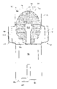
second foldable
tabs 68, 80, the foldable cover 184 may be folded toward the upper edge 124 of
the main panel
122 of the inner component 120 for at least partially covering the medical
implant 190 secured
to the inner component 120 and preventing the medical implant 190 from
shifting below the
lower edge 126 of the inner component.
[0065] Referring to FIGS. 4B and 4C, in one embodiment, the second panel 94
is folded
over the first panel 52 of the outer component 50 so that the upper edge 96 of
the second panel
94 is aligned with the upper edge 54 of the first panel 52. The locking flap
108 of the second
locking tab 106 preferably engages the upper edge 54 of the first panel 52,
and the first locking
flap 66 of the first locking tab 64 preferably engages the upper edge 96 of
the second panel 94
for holding the upper ends of the panels 52, 94 closed. Referring to FIG. 4C,
the medical
implant 190 is visible through the second window 104 of the second panel 94.
16
CA 02801711 2012-12-05
WO 2011/163197 PCT/US2011/041207
[0066] Referring to FIG. 4D, in one embodiment, after the second foldable
part 154 of the
first lateral locking tab 144 is passed through the elongated slot 79
extending between the first
foldable part 70 and the second foldable part 76 of the first foldable tab 68,
the second foldable
part 76 of the first foldable tab 68 is preferably folded over the first
foldable part 70 of the first
foldable tab 68. In one embodiment, after the second foldable part 172 of the
second lateral
locking tab 146 is passed through the elongated slit 92 extending between the
first foldable part
82 and the second foldable part 88 of the second foldable tab 80, the second
foldable part 88 of
the second foldable tab 80 is preferably folded over the first foldable part
82 of the second
foldable tab 80. When the second panel 94 is closed over the first panel of
the outer
component, the second foldable part 154 of the first lateral locking tab 144
is preferably in
alignment with the first locking slot 110 of the second panel 94, and the
second foldable part 72
of the second lateral locking tab 146 is preferably in alignment with the
second locking slot 112
of the second panel 94.
[0067] Referring to FIG. 4E, in one embodiment, the first foldable part 70
of the first foldable
tab 68 may be folded over the top of the second panel 94 and the second
foldable part 154 of
the first lateral locking tab 144 may be inserted into the first locking slot
110 for closing a first
side of the package 40. Referring to FIGS. 4E and 4F, in one embodiment, the
first foldable
part 82 of the second foldable tab 80 may be folded over the second panel 94
so that the
second foldable part 172 of the second lateral locking tab 146 may be inserted
into the second
locking slot 112 of the second panel 94 of the outer component 50.
[0068] FIG. 4F-1 shows the second foldable part 172 of the second lateral
locking tab 146
being inserted into the second locking slot 112 of the second panel 94 of the
outer component.
The first foldable part 82 of the second foldable tab 80 preferably overlies
the second panel 94
of the outer component. The upper end 180 of the second foldable part 176 of
the second
lateral locking tab 146 desirably includes a locking recess 182 formed therein
for reliably
securing the second lateral locking tab 146 with the second panel 94 of the
outer component 50.
[0069] Referring to FIG. 4G, in one embodiment, after the first lateral
locking tab 144 is
inserted into the first locking slot 110 and the second lateral locking tab
146 is inserted into the
second locking slot 112, the respective first and second foldable tabs 68, 80
desirably cover the
17
CA 02801711 2012-12-05
WO 2011/163197 PCT/US2011/041207
sides of the first and second panels 52, 94 of the outer component 50 for
holding the sides of
the panels closed. The upper locking tabs 64, 106 preferably hold the upper
edges 54, 96 of
the respective first and second panels together for holding closed the upper
ends of the panels
of the package 40. The medical implant 190 may be held by the inner component
120 (FIG. 2a)
and be disposed between the first and second panels 52, 94 of the outer
component 50.
[0070] Referring to FIG. 5A, in one embodiment, the second upper locking
tab 106
preferably engages the upper edge 54 of the first panel 52 for closing the
upper end of the
package. Although not shown in FIG. 5A, the locking flap 108 of the second
locking tab 106
desirably overlaps the upper edge 54 of the first panel 52. The locking flap
66 of the first upper
locking tab 64 preferably overlies the upper edge 96 of the second panel 94
for holding the
respective upper edges 54, 96 of the first and second panels 52, 94 together
for closing the
upper end of the package.
[0071] Referring to FIGS. 5A and 5B, in one embodiment, in order to open
the upper end of
the package, the second locking tab 106 is preferably pulled away from the
upper edge 54 of
the first panel 52 of the outer component 50. As the second locking tab 106 is
pulled away from
the first panel 52, the upper edge 96 of the second panel 94 is desirably
released from the first
locking flap 66 of the first upper locking tab 64.
[0072] Referring to FIGS. 5B and 5C, in one embodiment, as the first and
second panels
52, 94 are peeled or flexed away from one another, the medical implant 190 is
desirably
exposed and accessible at the upper end of the package. FIG. 5D shows how the
medical
implant 190 may project from the upper end of the medical package when the
first and second
panels 52, 94 are peeled away from one another. In FIG. 5D, the peripheral
edge 192 of the
medical implant 190 is accessible so that the implant may be removed from the
package for use
in a surgical procedure.
[0073] The packages for medical devices shown and described herein may be
utilized to
hold medical implants having various shapes and sizes. Although the medical
implant 190
shown in FIGS. 1-5D has an oval shape, implants having other shapes and sizes
may be
contained within the packages disclosed herein, such as circular implants,
square implants, and
rectangular implants. The flat implants stored in a package may have a length
of about 10-60
18
cm and a width of about 5-30 cm. Preferred implants may include those
disclosed in commonly
assigned U.S. Patent Application Serial Number 12/815,275.
[0074] While
the foregoing is directed to embodiments of the present invention, other and
further embodiments of the invention may be devised without departing from the
basic scope
thereof, which is only limited by the scope of the claims that follow. For
example, the present
invention contemplates that any of the features shown in any of the
embodiments described
herein, may be incorporated with any of the features shown in any of the other
embodiments
described herein, and still fall within the scope of the present invention.
19
CA 2801711 2017-10-11