Note: Descriptions are shown in the official language in which they were submitted.
CA 02802078 2012-12-10
1
Prosthesis for partial replacement of a tubular bone
The invention relates to a prosthesis for replacing at least part of a tubular
bone and an
adjoining joint. It comprises an elongate shaft having a first and a second
end, as well as a
joint mechanism arranged at the second end of the shaft. A length-adjusting
mechanism is
provided which displaces the shaft along its axis in the manner of a
telescope. The
invention moreover extends to a prosthesis module system with exchangeable
shafts.
Various types of endoprostheses have long been known as a replacement for
diseased or
defective bones and joints. Prostheses having a shaft extending over the
length of the bone
to be replaced are used to replace tubular bones, particularly on account of
tumour
diseases. The shaft replaces and/or reinforces the diseased or absent bone
portion. It is
frequently connected to a joint mechanism replacing an adjoining joint (for
example knee
or elbow). The dimensions of the prosthesis shaft must therefore be selected
in accordance
with the respective anatomy and pathology of the patient.
It is known to offer prostheses in different sizes so as to match individual
needs. However,
not even with fine grading is it possible to optimally suit the multitude of
different needs.
This applies all the more to patients who are still growing, i.e. children.
In order to also be able to sufficiently assist those patients, prostheses
have been equipped
with a length-adjusting mechanism. Thus, a knee prosthesis is known which
comprises a
shaft and a joint mechanism, with a telescope mechanism being provided in the
shaft to
CA 02802078 2014-11-24
23331-154
2
change the shaft length (US 4,384,373). In this arrangement length adjustment
of the shaft is
possible during surgery. No provision is made for subsequent adjustment.
In order to also be able to adjust the shaft length after surgery, a refined
prosthesis is known in
which a union nut is provided for actuation (US 4,502,160). It comprises an
external toothed
ring, the external toothing of which can be actuated by means of a socket key
to be laterally
inserted. The socket key can be passed through an incision, thus permitting
the length of the
shaft to be adjusted even after surgery.
To avoid rotation of the prosthesis, and more particularly rotation of the
shaft relative to the
joint, even when the length is being varied, a rotation lock may be provided
(US 4,892,446).
A locking screw prevents the shaft from rotating relative to the joint and is
loosened to allow
for length adjustment.
One disadvantage of these known prostheses is that they are highly specific in
each case
(actuatable after surgery, secured against rotation, etc.) and therefore only
have a narrow field
of application.
The invention is based on the object of further developing an endoprosthesis
of the kind
referred to initially so as to permit its use for a wider range of
applications.
In one aspect of the invention, there is provided a prosthesis for replacing
at least part of a
tubular bone and an adjoining joint, comprising an elongate shaft with a first
and a second
end, as well as a joint mechanism arranged at the second end of the shaft,
wherein a length-
adjusting mechanism is provided which actuates the shaft along an axis of the
shaft in the
manner of a telescope, the shaft and the joint mechanism being coupled via
complementary
connectors, wherein the length-adjusting mechanism is of a modular design and
proximal and
distal ends of the length-adjusting mechanism are provided with the
complementary
connectors, wherein a male connector is provided at one of the proximal and
distal ends of the
length-adjusting mechanism and a female connector is provided at the other one
of the
proximal and distal ends, and wherein the length-adjusting mechanism is
further provided
with a positive locking anti-rotation means.
CA 02802078 2014-11-24
23331-154
2a
In one aspect of the invention, there is provided a prosthesis system
comprising a prosthesis as
described herein and several shaft members of different lengths that can be
coupled via the
connectors.
In a prosthesis for replacing at least part of a tubular bone and an adjoining
joint, comprising
an elongate shaft having a first and a second end and a joint mechanism
arranged at the
second end of the shaft, wherein a length-adjusting mechanism is provided
which actuates the
shaft along its axis in the manner of a telescope, it is provided according to
the invention that
the shaft and the joint mechanism are coupled via complementary connectors,
wherein the
length-adjusting mechanism is of a modular design and is provided, at its
proximal and distal
ends, with the complementary connectors and is further provided with an anti-
rotation means
acting in a positive fit manner. Complementary is understood to mean that a
male connector is
provided at one of the two ends and a female connector is provided at the
other. The
connectors preferably are cone connectors.
The gist of the invention is the idea to design the length-adjusting mechanism
in a modular
manner and to additionally provide it at its proximal and distal ends with
exactly the same
type of connectors as are also provided at the transition between the shaft
and the
CA 02802078 2012-12-10
3
prosthesis joint. The length-adjusting mechanism is thus, unlike in the prior
art, not an
integral part of the prosthesis but can rather be inserted as required. It
can, so to speak, be
exchanged for a conventional standard shaft member without a length-adjusting
mechanism.
The invention thus allows practically any joint prosthesis to be provided with
a length-
adjusting mechanism in a simple and efficient manner. This significantly
improves the
adaptability of the prosthesis to the anatomical and/or pathological
conditions of the
individual patient, without this requiring a large number of different parts
having different
sizes. The joint mechanism may have practically any design and is able assist
or limit
movement in the joint to various extents ranging from completely free to
stiffened. Due to
the fact that, according to the invention, the length-adjusting mechanism is
distinct from
the actual joint prosthesis as a result of the modular design, the invention
can easily also
be applied to other prostheses as long as these include corresponding cone
connectors.
Due to the integrated anti-rotation means acting in a positive fit manner, no
further
requirements have to be met by the respective basic prosthesis so as to be
secured against
turning.
The anti-rotation means prevents undesired relative rotation of the shaft and
its
components. It is a further advantage of the structural integration of
securing against
turning and length adjustment that the actuating members can be located
closely next to
one another. Thus, adjustment after surgery requires access from only a
narrowly
delimited area. A minimally invasive stab incision is sufficient to change the
length of the
prosthesis. With such a gentle surgical technique, the prosthesis is
particularly also
suitable for use in children.
Preferably the shaft has an outer and an inner rod acted on by the length-
adjusting
mechanism. It is thus possible, using a suitable tool, to directly act on the
length-adjusting
mechanism which correspondingly displaces the outer rod relative to the inner
rod in the
manner of a telescope.
To ensure sufficient protection against inadvertent adjustment despite the
simple
adjustability, there is preferably provided a dual securing mechanism which,
besides
securing against rotation, also forms an adjustment lock by means of two
adjacent screws.
In this regard, it is furthermore preferred for one of the screws to be non-
rotatably
disposed on the outer rod and for the other to be rotatably disposed on the
adjustment nut.
The outer rod advantageously comprises a compression flange having two
opposite collar
faces, one of which is a thrust bearing for the conical connection and the
other forms a
CA 02802078 2012-12-10
, 4 ,
stop for length adjustment. This enables a very compact structure which also
allows the
length-adjusting mechanism according to the invention to be integrated into
relatively
small prostheses to be used, for example, on the elbow or the hand.
It may be expedient for a second shaft-length-adjusting mechanism to be
provided which
is preferably equipped with inversely disposed cone connectors. In the case of
long shafts,
particularly such used to replace the femur, this also allows the length to be
adjusted at the
other end. Not only does this extend the range of adjustment, it is also
frequently more
favourable from a physiological point of view.
The invention furthermore extends to a prosthesis system with several
connectable, rigid
shaft members of different lengths and a connectable length-adjusting
mechanism,
wherein preferably at least one of the rigid shaft members is the same length
as the length-
adjusting mechanism in its initial position. A prosthesis system may thus
include
prostheses having a shaft of fixed length or a shaft of adjustable length,
with it being
possible by simply exchanging a rigid shaft module for an adjustable-length
shaft module
to change from one design to another. This can also be done intraoperatively
so that the
surgeon may, depending on the circumstances of the case, decide during surgery
which
variant should be preferably used in the respective case.
According to a particularly advantageous variant which may possibly deserve
independent
protection, it is provided that in a prosthesis for replacing at least part of
a tubular bone
there is provided a mechanism for actuating the length-adjusting mechanism
which
comprises a thread on the inner rod and an adjustment nut which is screwed
onto the
thread and having a circumferential toothing, wherein on the outer rod there
is provided a
bearing bore for an adjusting wrench engaging the circumferential toothing. It
is
preferably provided that the adjustment nut liftably rests with its upper edge
on a front
face of the outer rod and cooperates therewith without undercut.
The gist of this aspect of the invention is the idea that only a very small,
patient-friendly
access opening is required when using the bearing bore for the adjusting
wrench. It is
possible therewith to frequently readjust the length and ¨ especially in
younger patients -
adapt it to growth. It is easily possible, due to the modular construction, to
exchange the
length-adjusting mechanism for a larger one when there is no more room for
adjustment.
Due its being preferably mounted in a free-floating manner, the adjustment nut
is axially
displaceable relative to the outer rod, namely it only rests on the front side
thereof without
being secured there by a positive fit guidance, particularly an undercut; the
adjustment nut
can thus be freely moved away from the outer rod.
CA 02802078 2012-12-10
Two substantial advantages are associated with this construction. On the one
hand, it
allows the parts of the prosthesis to be separated from each other. The wound
required for
implanting the tubular bone prosthesis may therefore be considerably smaller.
This is
clearly less onerous for the patient and easier to handle for the surgeon.
Another advantage is that, due to the feature of the adjustment nut being
mounted without
undercut, a greater force application surface becomes possible between the
adjustment nut
and the outer rod on the front face. Due to this greater force application
surface, the
prosthesis is thus subject to less strain and/or can be designed to be smaller
and thus
slimmer whilst offering the same robustness. It is precisely this last feature
that constitutes
a significant advantage as regards implantation in young patients.
It is known to adjust the length of the tubular bone substitute in a
prosthesis for replacing
a tubular bone including an adjacent joint by providing a bevel gear at the
transition
between joint and tubular bone (US 4,892,546). This admittedly offers the
advantage of
enabling adjustment of length without requiring a major surgical intervention.
It is,
however, a disadvantage that the required bevel gear is comparatively bulky.
Therefore,
this prosthesis is less suitable for application in young patients,
particularly in children.
Furthermore, a tubular bone prosthesis is known which has a telescopic shaft
including a
shaft and a sleeve, with a union nut being provided on the sleeve (US
4,502,160). The
union nut is axially guided on the sleeve, fixed thereto in a positive fit
manner, so as to be
able only to rotate, but not to move in the longitudinal direction. With its
internal thread,
the union nut cooperates with an external thread disposed on the shaft. The
length can be
changed by rotating the union nut. Due to the fact that the union nut is fixed
to the sleeve
in a positive fit manner, the prosthesis can only be implanted when fully
assembled. This
complicates implantation since a large access opening is required for the
fully assembled
prosthesis. As a result, the surgical wound thus becomes disproportionately
large, which
may represent a heavy burden especially to the group of young patients.
The prosthesis according to the invention is hence significantly less onerous
for patients
and is more advantageous as regards growth behaviour, it being thus
particularly suitable
for treating young patients (children) during their growth period. The reason
is that the
growth plate of the bone must frequently be resected during the implantation
process. The
prosthesis according to the invention is, however, perfectly suitable also for
application in
adults experiencing postsurgical changes, for example due to ligament
lengthening.
The circumferential toothening is preferably designed as a steep toothing.
Steep toothing
is understood to mean that the load-bearing flanks include a flank angle of
from at least
CA 02802078 2012-12-10
6
50 to no more than 85 , preferably at least 600. Such a steep orientation of
the load-
bearing flanks suppresses or largely avoids the generation of axial force due
to actuation
of the adjusting wrench and action thereof on the circumferential toothing of
the
adjustment nut. Undesired parasitic adjustment of length or undesired axial
displacement
caused by the adjusting wrench can thus be avoided. It is hence ensured that
the
adjustment of length is based solely on the axial displacement resulting from
rotational
movement of the adjustment nut due to the lead of the internal thread of the
adjustment
nut.
Preferably the toothing is embedded in an appropriate circumferential recess.
Here, the
recess is preferably formed on the outer edge of the upper side. By this
means, the
circumferential toothing does not protrude, i.e. no crests stick out in the
axial direction.
This efficiently obviates the risk of causing irritation to the surrounding
tissue.
The following moreover applies to all of the embodiments:
The internal thread of the adjustment nut preferably is a single-start thread.
Here, "single-
start" is understood to mean that there is just one thread which is continuous
from one side
of the nut to the opposite side. As a result of there being only one thread,
it is possible to
position the adjustment nut in a defined manner relative to the inner rod in
the direction of
rotation. This simplifies accurate alignment and thus length adjustment,
ruling out the risk
of positional ambiguities.
Preferably the thread of the inner rod is flattened. Here, "flattened" is
understood to mean
that the crests of the thread on the inner rod are chamfered, i.e. not pointed
in the narrower
sense of the term, but are rather replaced by a preferably flat area. This
flat area as a
whole forms a hollow cylindrical shell. The thread of the inner rod therefore
has less sharp
edges affecting its surroundings. This reduces the risk of irritation.
The adjustment nut advantageously has a polished peripheral surface. This
prevents the
surrounding tissue from adversely affecting the adjustment nut, and so there
is hardly any
adhesion. The adjustment nut thus remains adjustable even many years after
implantation
and is not blocked by tissue (connective tissue) growing over it. The polished
peripheral
surface can also be achieved by designing this surface in any other manner
leading to
reduced adhesion. Anodizing of the surface can be considered here,
particularly in case of
titanium endoprostheses.
The adjustment nut expediently has a plurality of radial holes on its
peripheral surface
which are preferably arranged at a regular angular distance. These radial
holes are for
CA 02802078 2012-12-10
7
accommodating an adjusting pin. This is inserted into one of these holes, thus
allowing the
adjustment nut to be rotated by a specific angular amount until the adjusting
pin has
reached its stop position. By reinserting the adjusting pin into one of the
other radial holes
which are preferably arranged at equal angles, it can be actuated again, with
the result of
achieving a turning of the adjustment nut and, thus, an adjustment of length.
This also
offers the advantage of permitting emergency actuation if the length-adjusting
mechanism
cannot be actuated by means of the adjusting wrench.
The adjustment nut expediently has a rounded tactile marking. This makes it
possible to
exactly define a "zero position" of the adjustment nut in the direction of
rotation. This is
expedient where the length to be readjusted or the growth in length is
transferred
mathematically, measured in rotations of the adjustment nut. In order to have
a zero
position here, the tactile marking is of great advantage. Expediently the
outer rod, which
has the adjustment nut abutting its front side, comprises an identically
shaped continuation
of the tactile marking. A harmonic transition thus results between the tactile
marking on
the adjustment nut and the continuation on the outer rod. This efficiently
obviates the risk
of causing irritation to surrounding tissue.
The inner rod advantageously has recesses provided thereon in which a latching
member
=
is engaged that is disposed on the outer rod. These recesses may be a series
of bores
disposed on the outside of the shaft. They are expediently disposed in an
axial groove.
Their purpose is to receive a screw being screwed therein which with its tip
engages in the
recess, thereby securing the inner rod against accidental axial movement.
Inadvertent
separation of the inner rod from the outer rod is safely avoided by this means
and can thus
be counteracted. The fastening screw is advantageously designed as a grub
screw. While
requiring little space, it can still ensure a sufficiently safe locking of the
length-adjusting
mechanism.
Preferably at least one of the two elements, i.e. the thread of the inner rod
and/or the
internal thread of the adjustment nut, consists of titanium-free material,
particularly
cobalt-chromium material. This offers the advantage ¨ specifically in
combination with
titanium, the material of choice in the fabrication of prostheses ¨ that
thread seizure will
not occur. Protection against inadvertent blocking of the thread, particularly
due to
seizure, represents a significant advantage for the tubular bone prosthesis
according to the
invention, the most important property of which is its longitudinal
displaceability. The
invention will now be explained with reference to the enclosed figures showing
advantageous example embodiments, in which:
CA 02802078 2012-12-10
8
Fig. 1 is a sectional view of a knee joint prosthesis according to a first
example
embodiment of the invention;
Fig. 2 is a front and lateral view of a total prosthesis based on the first
example
embodiment according to Fig. 1;
Fig. 3 shows exploded views of Fig. 2;
Fig. 4 is a sectional view of a variant;
Figs. 5a-e show how length adjustment is performed;
Fig. 6 is an exploded view of a second example embodiment of the invention;
Figs. 7a-c are enlarged detailed views of the second example embodiment;
Fig. 8 shows the function of a length-adjusting mechanism;
Fig. 9 is a fully assembled view; and
Fig. 10 is a perspective view.
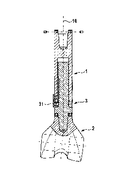
Fig. 1 shows an example embodiment of the prosthesis according to the
invention which
is intended as a joint prosthesis for replacing part of the knee and part of
the distal femur.
It comprises, as components, a shaft 1, a joint mechanism 2 and a length-
adjusting
mechanism 3. The shaft 1 comprises an outer rod 11 and an inner rod 2 guided
inside the
outer rod 11 so as to be telescopically displaceable along its central axis
10. The outer rod
12 has at its first end a female cone connector 19 which is for coupling
further rod
segments (not shown in Fig. 1) as needed; it should be noted that it may also
be sealed by
a blind plug or may be dispensed with altogether. At its second end the outer
rod has a
front flange 13 with a radially oriented front face. The inner rod 12 has at
its first end a
complementary, male cone connector 18 adapted to engage in a matching female
cone
connector 29 on the joint mechanism 2. At the transition to the cone connector
18, the
inner rod 12 has a collar 14, one end face of which, facing the fixed end,
serves as a stop
for the cone connector 18, and the other face of which, facing the shaft of
the inner rod 12,
serves as a stop for an adjustment nut 30.
The actuating mechanism 3 comprises the adjustment nut 30 having a single-
start internal
thread 39 which meshes with a single-start adjustment thread 32 disposed on
the inner rod
CA 02802078 2014-11-24
23331-154
9
12. The adjustment nut 30 has at its lateral faces a plurality of engagement
apertures 31
configured as radial bores. They are adapted to receive a pin 9 (see Fig. 5c)
as an
actuating member. This is used to rotate the adjustment nut 30 relative to the
inner rod 12
=
having the mating thread 32, by means of which the adjustment nut 30 moves
along the
central axis 10. In its initial position, the adjustment nut 30 is directly
contiguous with the
front flange 13 of the outer rod,11 and takes the latter with it as it moves.
This causes the
outer rod 11 to move along the longitudinal axis 10 relative to the inner rod
12 such that
the distance between the adjustment nut 30 and the collar 14 increases, as
does the overall
length of the shaft 1. When the adjustment nut 30 is rotated in the opposite
direction, the
process takes place in the reverse direction and the overall length becomes
shorter.
Securing mechanisms are provided to fix a set length. These include an
adjustment lock
35 and an anti-rotation means 37. The adjustment lock 35 comprises a clamping
screw
which is inserted in one of the radial bores 31 of the adjustment nut 30 and
acts with its tip
on a flat portion 15 on the inner rod 12. As a result, the adjustment nut 30
is locked in a
positive fit manner. It is thus ensured with certainty that even under heavy
and frequently
varying loads there can be no inadvertent rotation of the adjustment nut 30
with a
corresponding change of length. The anti-rotation means 37 is similar in
structure and has
a fixing screw disposed in a radial bore in the region of the front flange 13
on the outer
rod. This fixing screw acts with its tip in the region of the mating thread
32, thus securing
the outer rod 11 against rotation relative to the inner rod 12. Accidental
rotation of the
inner rod 12 relative to the joint mechanism 2 is in turn prevented by means
of two
diametrically opposed fixing screws of a conical lock 27 that is known per se.
As a result,
rotation is prevented continuously from the joint mechanism 2 to the length-
adjusting
mechanism 3 and the shaft 1.
The length adjustment process is illustrated in Fig. 5 on the example of an
implanted
prosthesis that is to be adjusted to greater length so as to accommodate for
the patient's
growth. This requires first of all that the prosthesis be accessed by means of
minimally
invasive surgery. A stab incision is normally sufficient for this. In a first
step (Fig. 5a), a
screwdriver 8 is slid through the incision and is engaged with the securing
screw for the
anti-rotation means 37. The anti-rotation lock is released by unscrewing the
screw. In a
second step (Fig. 5b), the adjustment lock 35 is released in just the same
way. The length-
adjusting mechanism 3 thus becomes disengaged and can be actuated. The
screwdriver 8
is removed and an adjusting pin 9 is inserted through the incision and engaged
with one of
the radial bores 31 of the adjustment nut. By swivelling the pin 9, the
adjustment nut 30 is
rotated to some extent, then the pin 9 is reinserted into an adjacent radial
bore and the
adjustment nut 30 is rotated some more. In the example embodiment shown, the
thread
lead is selected such that a change in length of 2 mm results per revolution
of the
=
CA 02802078 2012-12-10
adjustment nut 30. Once the desired length has been set, the pin 9 is
withdrawn and the
screwdriver 8 is introduced once again to successively reinstall, and thus
reactivate, the
adjustment lock 35 (Fig. 5d) and the anti-rotation means (Fig. 5e).
The embodiment illustrated in Fig. 1 shows a basic prosthesis. This can be
supplemented
with additional elements, as depicted in Figs. 2 and 3. There, additional
shaft segments 5,
6 are provided which are joined via cone connectors matching the cone
connectors 18, 19
of the shaft 1 and 29 of the joint mechanism 2 so as to form a long shaft (see
exploded
view in Fig. 3). At the upper end thereof, there is arranged a femoral neck
prosthesis 7. A
total femoral prosthesis is thus formed which, unlike in the prior art, cannot
just be
designed to have graduated lengths but is rather, thanks to the modular length-
adjusting
mechanism 3, even steplessly adjustable. This allows for fine adjustment. With
the length-
adjusting mechanism 3 in an initial position (as shown in Fig. 1), the shaft 1
preferably is
the same length as one of the shaft segments, for example the shaft segment 5.
As a result,
a prosthesis system is provided in which an adjustable-length or fixed-length
shaft can be
formed, as needed, by simply replacing the elements 1, 5.
An alternative embodiment is illustrated in Fig. 4, wherein identical elements
are
identified by the same reference numbers. The difference to the first example
embodiment
essentially lies in that the outer rod 11' and the inner rod 12' are inversely
arranged, i.e.
the outer rod 11' is arranged on the joint mechanism 2 and the inner rod 12'
forms the first
end with the cone connector 19. Such an inversely designed length-adjusting
mechanism
3' may also be provided on the first end of a long shaft having several shaft
segments 5, 6,
as shown in Fig. 3.
Reference will now be made to the second example embodiment as shown in Figs.
6 to
10. This comprises a particular actuating mechanism for the length-adjusting
mechanism.
Elements of the same type are identified by the same reference numbers. An
insertion area
43 extends from the collar 14 to the other, free end of the shaft 12. This
insertion area
comprises the external thread 32. This is a single-start thread and the cross-
sectional shape
of the individual threads is substantially triangular with a flattened crest.
Furthermore, the
inner rod comprises, except in a short guidance portion 45 which approximately
corresponds to 1.5 times the rod diameter, a longitudinal groove 46 having
configured at
its bottom a number of blind holes 47 in a line oriented in parallel to the
longitudinal axis.
A tactile marking 55, configured as an elevation, is disposed on the
substantially smooth
outer surface of the adjustment nut 30 (see Fig. 7a). Eight counterbores 57
are also
disposed on the outer surface at a regular angular distance and in a uniform
radial plane,
one of which being disposed in the tactile marking 55. At its lower edge
facing the inner
CA 02802078 2012-12-10
11
rod 12, the adjustment nut 30 is designed to be complementary to the collar 14
and
includes a planar outer contact surface 52. The internal thread 39 is disposed
in a portion
of the adjustment nut 30 that is made from cobalt chrome (CoCr); preferably
the entire
adjustment nut 30 consists of cobalt-chromium material.
The adjustment nut has at its upper edge a circumferential toothing 81 which
is part of an
actuating mechanism 8. The toothing 81 has an undulating profile with rounded
crests 82
and roots 83. The flanks 84 joining the crests 82 and the roots 83 are
designed as steep
flanks having in their central part an inclination (based on the radial plane
as defined by
the upper edge 56) of 60 . The roots 83 ascend from the outside to the inside,
resulting in
a conically tapered tooth structure, as is suitable particularly for a right-
angle gear drive.
The toothing 81 is disposed on a recess 80 extending along the outside of the
upper edge
56, such that the crests 82 do not protrude, but finish flush with the plane
defined by the
upper edge (see Fig. 9; outer rod not shown for the sake of greater clarity).
As a result,
there is some kind of double-shell structure on the upper edge, with a
circumferential
inner ring forming a planar and undercut-free contact surface as an inner
shell, and with
the toothing 81, the rounded crests 82 of which finish flush and level with
the inner ring
56', as the outer shell.
The front flange 13 of the outer rod 11 is substantially planar, it being in
particular devoid
of undercuts, i.e. nowhere is there an undercut. On the outer surface of the
outer rod 11,
there is disposed a second protrusion 51 adjacent to the edge. It has a radial
bore 38 acting
as a bearing seat for an adjusting wrench 89 of the actuating mechanism 8. The
distance
between the radial bore 38 and the front flange 13 is adapted to the
dimensions of the
adjusting wrench 89, as will be described in more detail in the following.
A grub screw 37 can be provided as a locking instrument on the outer rod 11.
It is
preferably capable of being screwed into the bearing bore 38 and protrudes
with its tip, in
the screwed-in position, into the longitudinal groove 46, to be precise into
one of the blind
holes 47, thus securing the inner rod 12 against undesired dislocating
movements.
The adjusting wrench 89 is structured in the same manner as a bevel gear key
as is known
for actuating chucks. It comprises at its rear end an actuating handle 88
which, in the
simplest case, may be a cross bar. At the front end there is provided a
conical toothing 86
which is designed so as to be able to mesh with the toothing 81 of the
adjustment nut 30.
To engage the conical toothing 86 with the toothing 81, a bearing pin 87 is
formed on the
front tip that is designed to be complementary to the radial bore 38, with the
result that a
pivot bearing is formed. The distance from the radial bore 38 to the front
flange 13 is
adapted to the diameter of the conical toothing 96 in such a manner that, when
the
CA 02802078 2012-12-10
12
adjusting wrench 89 is inserted in the radial bore 38, the conical toothing 86
is engaged
with the toothing 81 of the adjustment nut 30 which with its upper edge lies
flush against
the front flange 13 of the outer rod 11.
The actuating mechanism 8 is actuated as follows. In its initial state, the
adjustment nut 30
is screwed onto the external thread 32 of the inner rod 12. The latter is
pushed into the
outer rod 11 until the upper edge of the adjustment nut 30 lies flush against
the front
flange 13 of the outer rod 11. By turning the adjusting wrench 89, which is
inserted in the
bearing bore 31, the conical toothing 86 thereof meshes with the toothing 81
of the
adjustment nut 30, by means of which the latter is turned and the inner rod 12
is pushed
out of the outer rod 11. The pushing distance is determined here by the lead
of the external
thread 32 cooperating with the adjustment nut 30 and by the gear ratio between
the
conical toothing 86 and the toothing 81. During adjustment, the adjustment nut
30 remains
contiguous with the outer rod 11.
If growth of the patient (or a lengthening in supporting ligaments) gives rise
to femoral
lengthening, the endoprosthesis according to the invention can be adapted
thereto. This is
done by readjusting the adjustment nut 30. It is sufficient for this to just
insert the driving
tool 89 into the bearing bore 38 by means of a minor and thus patient-friendly
intervention, and the adjustment nut 30 is readjusted by turning. The amount
of
readjustment is unambiguously determined by the number of revolutions of the
adjusting
wrench 89. In order to be easily able to control the number of revolutions,
there is
provided the tactile marking 55 on the adjustment nut 30. In its initial
position, it is flush
with the protrusion 51 of the same kind on the outer rod 11 and it always
returns to the
flush position whenever the adjustment nut 30 has made one complete
revolution. This
makes it possible to easily verify, by touch, the correct position from the
outside as well,
In order to ensure proper functioning of the actuating mechanism 8 even after
long-term
implantation, there are provided a toothing protector ring 50 having a moulded-
on section
52 for the conical toothing 86 of the adjusting wrench 89 and a multi cover 53
including
several (i.e. three in the example embodiment shown) pin stubs 54 (see Figs.
7b, c). The
toothing protector ring is disposed between the adjustment nut 30 and the
front flange 13
of the outer rod 11 and covers the toothing 81 at the outside. This prevents
tissue growing
into the toothing and the associated risk of blockage. To further prevent
growth into the
radial bores 31, 38, there is provided the multi cover 53. This is a
substantially cuboid
block inserted with its pin stubs 54 into the radial bores 31, 38 and held
clamped therein.
It covers the area shown hatched in Fig. 10 and thus reliably prevents
undesired growth of
tissue. For length adjustment, it only needs to be removed so as to allow
unrestricted
access to the screws 35, 37 as well to the toothing 81.
CA 02802078 2012-12-10
13
To receive the bearing pin 87 of the adjusting wrench 89, there is provided,
in the variant
shown in Fig. 10, a discrete bore that is distinct from the bore in which the
screw 37 is
received to offer protection against rotation (instead of the combined design
as shown in
Figs. 1 to 8).